9. Embedded programming
assignments for this week
- Individual: read a microcontroller data sheet. program your board to do something, with as many different programming languages and programming environments as possible.
- group assignment: compare the performance and development workflows for other architectures.
Summary
In this week I tested and debuged the proposed program of the ATtiny44 with a button and a led.
I also took same time to dig into markdown extensions, on the mkdocs.yml. In order to have the site more readable. I found this issue in week 5, but I didn’t manage to get it working. In this site, I found usefull documentation, even to use math formulas and other lists and notes, warnings, info, bugs, summary, tips… . This site also helps.
I reviewed the Neil week 9 lesson, found other video and tutorials on this subject, even the relationship between logic and arithmetic and begining to have a clue in understanding the microcontroller architecture: how computers make calculations, how registers function as really short memories, what is the BUS function, how they are built, the internal design logic gates, adders and manage to try to write a 8-bit word to open a pinB3 using the ATtiny44 datasheet.
I programed the board to blink a LED. I found a lot of trouble using Mac for programming the board, but succeeded. I manage also to program the button to control the LED. for the ” and for the “hello world” outcame. Debugging the software was another issue. Serial communication, pullup resistors was also a serious issue. So many variables to debug.
For the group assignment I discuss the workflow that my calleague, Mónica Pedro, used in the Machine Design week with RASP PI documented here.
Todo
- How computers make calculations
- Relationship between the programing and the pin gate logic
- Understanding Instruction set
- programing using Mac
- group assignment: try raspberry pi (ARM processor)
- toolchain C programing with the terminal: Neil hello world’s
- toolchain description reviewing
- Simulating
Work done
After reviewing the week 9 lecture, we followed this steps in order to have the chip programed with the ISP done previously.
Testing speeds
Note
just for fun… testing your computer speeds.
Harvard vs von Newman architecture
Harvard: program and data are in different memories. von Newman: program and data in the same memory.
RISC (Reduced Instruction Set Computer) - processors that have simple Instructions CISC (Complex Instruction Set Computer) - big complex instructions.
Bug
The first bug on a computer was really a bug! It was discovered by Grace Hopper, a navy officer at that time working on the Harvard Mark II computer. Mark I was rebooted in 2014.
ATtiny 44 is a CMOS (complementary metal-oxide-semiconductor) 8-bit RISC microcontroller with an AVR architecture (based on Harvard architecture). It runs at 20 MHz, since its a RISC it thus an instruction per 50 ns: it can do several 8-bit instructions in one cycle at 20 MHz.
| components | Features 1 | Description | Session |
|---|---|---|---|
| Flash | 4K bytes | To store programs | Memory |
| EEPROM | 256 bytes | Keeps the value after the power is turned off, to store settings | Memory |
| SRAM | 256 bytes | Static RAM memory to acess quickly to data | Memory |
| DRAM | not available on this microcontroller | Dynamic RAM, not so fast as SRAM but denser, to make bigger memories | Memory |
| Fuse memory | calculate it here | Memory | |
| Registers | 32 | word size: 8 | One kind of memory that stores data for just a moment, and retrieve or send data to the BUS 2 |
| Instruction register | This is doing the instructions | Everything his happening in this bit, everything else are peripherals | memory |
| I/O | 12 | peripheral | |
| I/O portB3 3 | Example: PORTB3 | Adress Read 0x18, bit no. 3 in Port B | 11000 0100 |
| A/D | Convert analog to digital, see this explanatory video | peripheral | |
| comparator | Compare voltages, just telling if it is lower or higher | peripheral | |
| D/A | Transform digital into analog | peripheral, not available at ATtiny44 | |
| Time-counter | 8-bit | measure time | peripheral |
| Counter | measure counts | peripheral | |
| PWM channels | 2 | Pulse with modulation, duty cycle (%) and fequency (Hz), see this, at time 3:22 video and this other practice reference | peripheral |
| Time-counter | 16-bit | measure time | peripheral |
| USART | Serial comunication | peripheral | |
| USB | Hardware USB protocol | peripheral |
| More components | Features 1 | Description | Part |
|---|---|---|---|
| Interrupts | Internal and External | peripheral | |
| ??? | 8-channel 10-bitADC | ||
| 12 differential ADC channel pairs | programmable gain stage (1x, 20x) | ||
| Watchdog Timer | programable with internal oscillator | ||
| calibrated oscillator | internal | ||
| power saving modes | 4 | ||
| Idle mode | stops the CPU while allowing the SRAM, Timer/Counter,ADC, Analog Comparator, and Interrupt system to continue functioning | ||
| ADC Noise | Reductionmode minimizes switching noise during ADC conversions by stopping the CPU and all I/O mod-ules except the ADC. | ||
| Power-down mode | registers keep their contents and all chip functionsare disbaled until the next interrupt or hardware reset | ||
| Standby mode | crystal/resonatoroscillator is running while the rest of the device is sleeping, allowing very fast start-up combinedwith low power consumption |
Note
microcontroller vs microprocessor: microcontroller has a CPU, in addition with a fixed amount of RAM, ROM and other peripherals all embedded on a single chip while microprocessor has only a CPU embedded on a single chip. source here
Starting to read the ATtiny44 datasheet, each part of the microcontroller as a registers, that’s where you configurer it.
The instruction set4, also called ISA (instruction set architecture), is part of a computer that pertains to programming, which is basically machine language.
The instruction set4, provides commands to the processor, to tell it what it needs to do.
The instruction set*4 consists of addressing modes, instructions, native data types, registers, memory architecture, interrupt, exception handling, and external I/O.
Understanding the relationship between bits and software
Follow this tutorials and projects to understand whats going on at the microcontroller: - Megaprocessor - How computers add numbers - BUS and registers - Bits Math Tutorial - Logic gates
Note
“George Boole proposed that logical propositions should be expressed as algebraic equations. The algebraic manipulation of the symbols in the equations provides a fail-safe method of logical deduction, i.e. logic can be reduced to algebra. He replaced the operation of multiplication by the word AND and addition by the word OR. The symbols in the equations can stand for collections of objects (sets) or statements in logic. For example, if x is the set of all pink pigs and y is the set of all fat pigs, then x+y is the set of all pigs that are pink or fat, and xy is the set of all pigs that are pink and fat.” Source 5
Program the board: toolchain
We can program the board with the [terminal] (https://www.gnu.org/software/make/manual/html_node/Introduction.html#Introduction) or the ARDUINO IDE: you can learn to use the ATtiny with the Arduino IDE here.
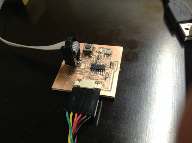
After preparing the board,
I turned to another 2018 Fab Academy Student, Solomon Embafrash, that also uses Mac IOS and followed the steps proposed and found that I didn’t have the proper avrdude version. I installed using this tutorial, where there was a need to install homebrew.
On week 7 I programmed the ISP with the Atmel-ice. I did found a lot of issues when using Mac but managed to work trough since I found that the avrdude version was one of thei issues. Now there is no need to use it again. I remove the soldering jumper and start to use the ISP.
For debuging I use in the Linux system already prepared by Filipe in order to see if it was working properly. We also tested with Arduino IDE and it work fine after soldering again: it stops working suddenly, some wires were loose.
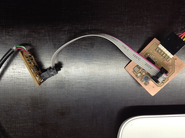
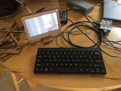
I connected as the picture above shows and followed the Neil tutorial…
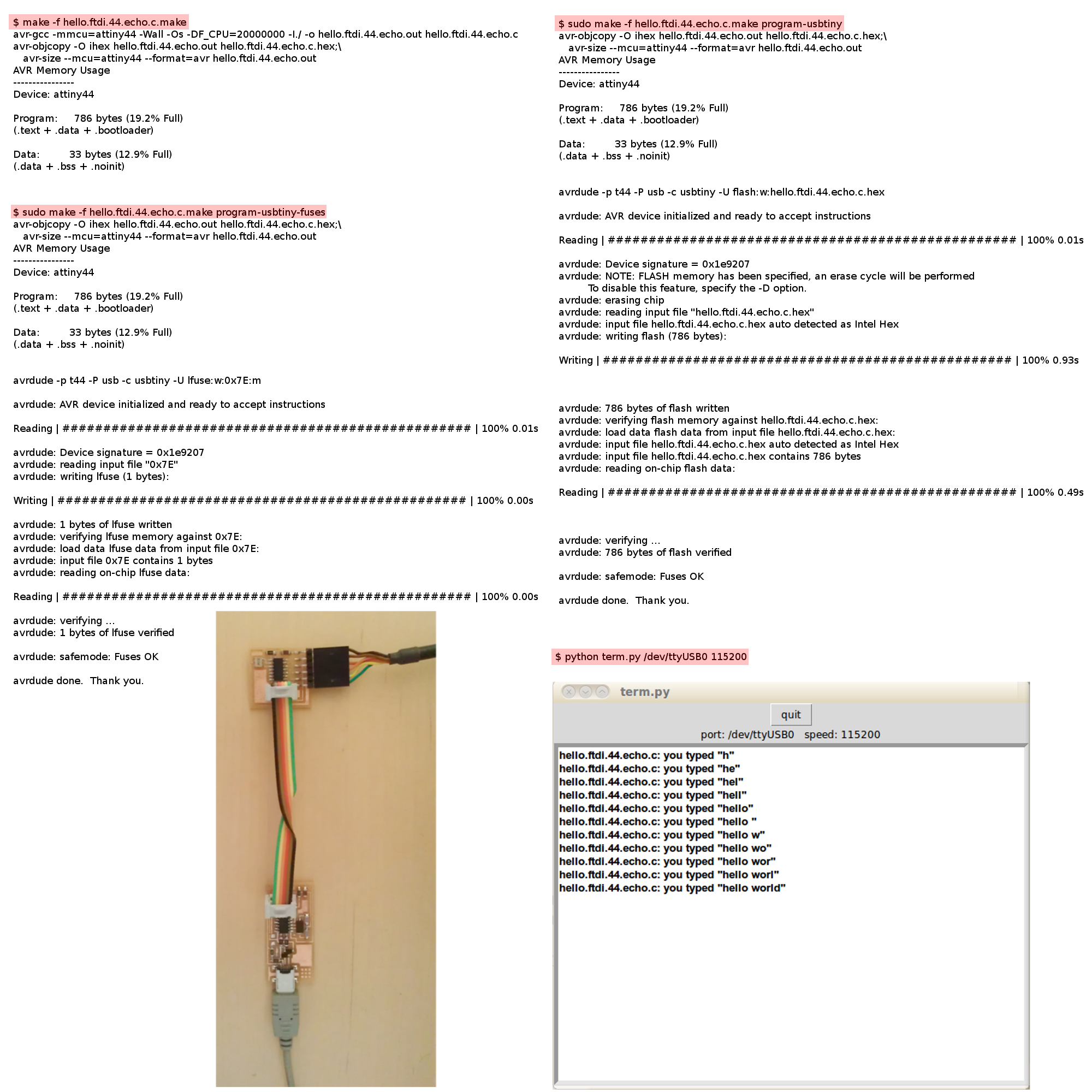
…in order to:
-
compile the code
-
set the fuses
-
program the board.
I did this using Linux but now I want to use a MAC.
Programing with Mac: Mac toolchain.
I started to define the tools in the ARDUINO IDE. It missed the ATtiny44 board so I went here. Copy the URL, past it in the “Aditional Boards manager URLs”. To get it, in the menu, follow this: ARDUINO → PREFERENCES.
Another way to use the ATtiny is to install homebrew and use the terminal. To see if all went well with the RS232 follow this tutorial.
Tip
If it doesn’t work try this URL
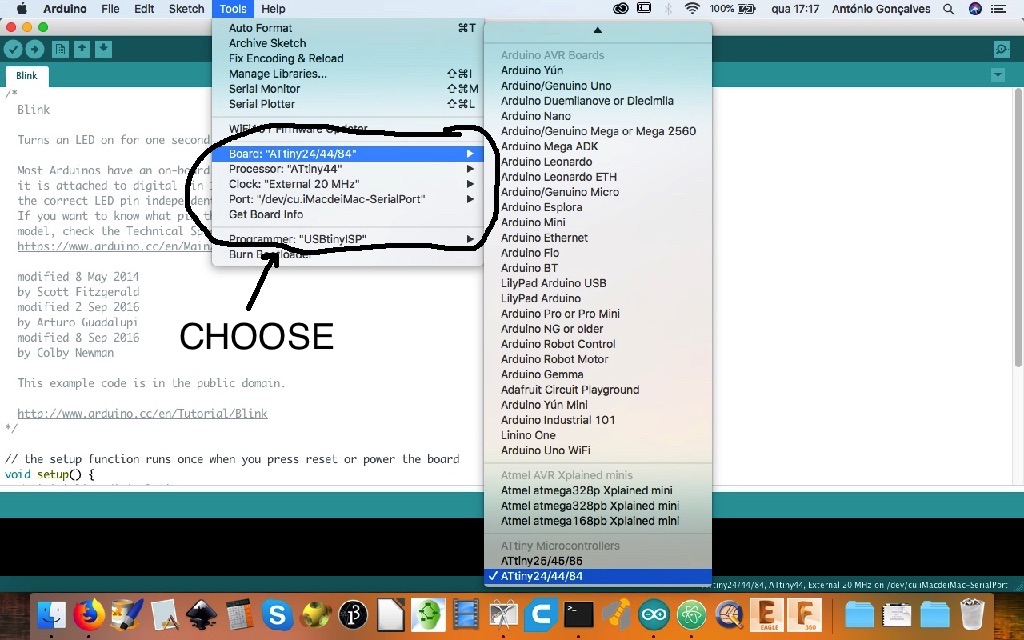
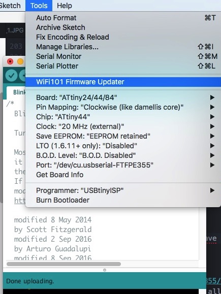
The complete tool selection menu is:
Even so, I get this error:
avrdude: Expected signature for ATtiny44 is 1E 92 07
         Double check chip, or use -F to override this check.
Wrong microcontroller found.  Did you select the right board from the Tools > Board menu?
I tried it with LINUX, the ISP is working. But, changing to Mac… I get this failure…
Failure
Arduino: 1.8.6 (Mac OS X), Board: “ATtiny24/44/84, Disabled, ATtiny84, 8 MHz (internal), EEPROM retained, B.O.D. Disabled, Clockwise (like damellis core)”
(…blá blá blá…)
avrdude: Version 6.3, compiled on Jan 17 2017 at 12:01:35 Copyright © 2000-2005 Brian Dean, http://www.bdmicro.com/ Copyright © 2007-2014 Joerg Wunsch
 System wide configuration file is "/Users/antoniocarlosgoncalves/Library/Arduino15/packages/arduino/tools/avrdude/6.3.0-arduino9/etc/avrdude.conf"
 User configuration file is "/Users/antoniocarlosgoncalves/.avrduderc"
 User configuration file **does not exist** or is not a regular file, skipping

 Using Port                    : usb
 Using Programmer              : usbtiny
avrdude: usbdev_open(): Found USBtinyISP, bus:device: 250:005 AVR Part : ATtiny84 Chip Erase delay : 4500 us PAGEL : P00 BS2 : P00 RESET disposition : possible i/o RETRY pulse : SCK serial program mode : yes parallel program mode : yes Timeout : 200 StabDelay : 100 CmdexeDelay : 25 SyncLoops : 32 ByteDelay : 0 PollIndex : 3 PollValue : 0x53 Memory Detail :
                          Block Poll               Page                       Polled
   Memory Type Mode Delay Size  Indx Paged  Size   Size #Pages MinW  MaxW   ReadBack
   ----------- ---- ----- ----- ---- ------ ------ ---- ------ ----- ----- ---------
   eeprom        65     6     4    0 no        512    4      0  4000  4500 0xff 0xff
   flash         65     6    32    0 yes      8192   64    128  4500  4500 0xff 0xff
   signature      0     0     0    0 no          3    0      0     0     0 0x00 0x00
   lock           0     0     0    0 no          1    0      0  9000  9000 0x00 0x00
   lfuse          0     0     0    0 no          1    0      0  9000  9000 0x00 0x00
   hfuse          0     0     0    0 no          1    0      0  9000  9000 0x00 0x00
   efuse          0     0     0    0 no          1    0      0  9000  9000 0x00 0x00
   calibration    0     0     0    0 no          1    0      0     0     0 0x00 0x00

 Programmer Type : USBtiny
 Description     : USBtiny simple USB programmer, http://www.ladyada.net/make/usbtinyisp/

 avrdude done.  Thank you.
Diging into the ATtiny chip failires, I manage to select the wright items.
Success
What was wrong? I really don’t know, I try and try and didn’t succeed but only with this options selected I achieve this goal (see the video bellow):
“Hello world” in sequence…
Blink a Led
I used pin 8 for the LED and pin 7 for the switch. This is the blink led. The result:
Switch the Led
I use this simple code:
  Button
  Turns on and off a light emitting diode(LED) connected to  ATtiny44 digital pin 8,
  when pressing a pushbutton attached to pin 7.

int button = 7;     // pushbutton pin
int led =  8;      // LED pin

void setup() {
  // LED pin as an output
  pinMode(led, OUTPUT);
  // pushbutton pin as an input
  pinMode(button, INPUT_PULLUP);//PB07 has internal resistors (and PB also, by the way)
}

void loop() {
  // read the state of the pushbutton value:
  int State = digitalRead(button);

  // check if the pushbutton is pressed. If it is, the buttonState is HIGH:
  if (State == HIGH) {
    // turn LED on:
    digitalWrite(led, HIGH);
  } else {
    // turn LED off:
    digitalWrite(led, LOW);
  }
}
Note
Debugging was a little bit dificult (at the same time I add the serial comunication issue) to find this internal resistors but all PB and PA at this chip as internal pullup resistors.
The result:
Hello world
For this part, I get inspiration on this FAB ACADEMY student, Gustavo de Abreu. But before doing “echo”, I decided to make a program based on the Arduino “SerialCallResponse” example. The program came out like this:
int button = 7; // pushbutton pin
int led = 8; // LED pin

void setup() {
  // LED pin as an output
  pinMode(led, OUTPUT);
  // pushbutton pin as an input
  pinMode(button, INPUT);
}

void loop() {

  // read the state of the pushbutton value:
  int State = digitalRead(button);
  Serial.begin(9600);

// check if the pushbutton is pressed. If it is, the buttonState is HIGH:
if (State == HIGH) {
  // turn LED on:
  digitalWrite(led, HIGH); }
  else { // turn LED off:
    digitalWrite(led, LOW);
    Serial.println("hello");       // print as an ASCII-encoded decimal
    }
    }
Failure
After I changed to have serial comunication the program went wrong, the Led doesn’t work and window serial only shows backwards ?????????????????
Hyphotesis: it uses a lot of memory, and the system is unstable: strange because its a program with so few lines of code; the serial connections are not correct? The software codes needs sommething else? The fuses are not correct? …
SOLUTION (sites I Used to overcame this issue.) - Help: https://www.circuito.io/blog/arduino-debugging/ - I found an error on my PCB: the capacitor is at the wrong place, wrongly welding. - Another strong error: TX and RX not at the wright place: TX - pin 12 - Arduino pin 1; RX - pin 11 - Arduino pin 2. - Not a problem of memory, I did the code wwith just 52% of memory, and the problem is at the serial communications; - The USB RoHS TTL 232R-5v color wires are correct.
The ISP: serial programming: what those pins are for?
The bootloader is important because your chip needs to know what to do with the bits you are sending to program your IC: in what “places” you want your program. You can do this using the ISP six connectors: MOSI, MISO, CLOCK, VCC, RESET and GND; The RESET is important because you need this IC pin HIGH for your chip to do nothing until the program is loaded; while the VCC and GND are simple to explain because your board needs energy, the MOSI, MISO and CLOCK are directly linked to the programming itself: in brief, the ISP is an 8-bit shift register in both the Master and the Slave, and a clock signal generated by the Master. The 8 bit data must be transfered between the master registers and the slave registers controlled by the clock: the master send 8 bits, the slave register record, and the clock stop the recording saying that was the byte. NEXT! In this case, we connect the SPI (Serial Peripheral Interface) Lines to the ISP (In-system Programming) Interface. The SPI is a peripheral used to communicate between the AVR and other devices.
Info
MISO (Master In Slave Out): the input of the Master’s shift register, and the output of the Slave’s shift register. MOSI (Master Out Slave In): the output of the Master’s shift register, and the input of the Slave’s shift register. SCK (Serial Clock): In the Master, this is the output of the clock generator. In the Slave, it is the input clock signal.
See page 4 of this datasheet for the AVR abreviations.
See this reference for more details about this and also SPI communication.
Sharing ISP pins
The Microchip datasheet adresses this issue: there is a need to include resistors: see p. 10 of this microchip datasheet
RESET external switch on the AVR
Refer to page 8 of this microchip datasheet. Between the RESET pin and the switch put a 330 ohm resistor. The other side of the button switch is connected to GND.
- Code: https://www.arduino.cc/en/Tutorial/SoftwareSerialExample
- http://highlowtech.org/?p=1695
- http://fabacademy.org/2019/docs/FabAcademy-Tutorials/week08_embedded_programming/attiny_arduino.html
- http://academy.cba.mit.edu/classes/embedded_programming/hello.ftdi.44.echo.c
- http://fabacademy.org/2019/labs/barcelona/students/gustavo-deabreu/assignments/week07/
- https://www.arduino.cc/en/Tutorial/SoftwareSerialExample
- http://fab.cba.mit.edu/classes/863.09/people/ryan/week5/ATtiny44%20Data%20Sheet.pdf
- http://academy.cba.mit.edu/classes/embedded_programming/index.html#echo
- https://www.arduino.cc/reference/pt/language/functions/communication/serial/begin/
- http://www.ernstc.dk/arduino/tinycom.html
- UART: https://en.wikipedia.org/wiki/Universal_asynchronous_receiver-transmitter
- pin ATtiny: https://camo.githubusercontent.com/20e6f39dffd62728b43bcc1fad25c4a5ae93b90f/687474703a2f2f6472617a7a792e636f6d2f652f696d672f50696e6f75745438342e706e67
- MAC terminal: https://www.macobserver.com/tips/quick-tip/download-files-terminal/
- RTS/CTS:
- Microchip, ATtiny44: https://www.microchip.com/wwwproducts/en/ATtiny44
Simulating
http://www.virtualbreadboard.com/ https://library.io/
References
- AVR Tutorial
- Tutorial AVR
- Arduino URLs boards
- microprocessors speeds
- Simple CPU
- Lecture 6 – Introduction to the ATmega328 and Ardunio
- programin in C
- assembly language
- Input/output pins on the Arduino
- Digital I/O Project on AVR® Xplained 328PB
- Port Registers
- Bit Math Tutorial
- 74HC/HCT5958-bit serial-in/serial or parallel-outshift register with output latches;3-state
- Instruction set summary
- Instruction Set Nomenclature
- ATmega328P datasheet
- learn C
Advanced - https://en.wikipedia.org/wiki/Logic_in_computer_science
Group assignment
In the group assignment we compare the workflows between the atmega328p and the Rasp pi. The first I have already same experience, the former, although I used, never explore in deep like Mónica.
Raspi, is a “single-board computer (SBC) is a complete computer built on a single circuit board, with a microprocessor, memory, input/output (I/O) and other features required of a functional computer”, source: https://en.wikipedia.org/wiki/Single-board_computer. It doesn’t provide a comfortable working environment or user friendly programs with graphical interfaces. I used IOS Raspbiam installed on the Broadcom system on a chip (SoC) with an integrated ARM-compatible central processing unit (CPU) and on-chip graphics processing unit (GPU). Off course is not so fast as normal computers,its necessary to develope some work habits that make the process tolerable. For instance, there is a natural need to install same programs like PIP in order to be more user friendly all the linux natural comands at the terminal, like, installing external Python modules. It can run under RISC OS.
With the Atmega processor family there is a natural environment named Arduino IDE that helps a lot to use this small chips.
They are both RISC architecture processors and the ARM is faster them the AVR: but, there are same buts for this. For specific tasks, sometimes its best to use the AVR.
Since the RAspi as a OS Raspbian it can run different things at the same time.
Nano
The nano editor its ok but its kind dificult to manage, for instance, program lines copy. So its better to use a normal text editor.
To start follow this PIP starting page. Here are same basic commands.
This workflow comparing between the AVR and the ARM was real in the two weeks of group work at the machine design that Mónica documented.
My favorite personal computer. A project in mind: making a lot of this using the laser cutter for the supports:
The main diferences, besides the code where Arduino is programable using arduino script or C/C++ with lots of libraries that help a lot, its the easyiest way to program because it uses Arduino Ide and the pins are defined by simple numbers, for instance. Its possible to use C-code or even other wasy of coding, using friendly interfaces.
Otherwise, the Raspberry Pi is a general-purpose computer, with a Linux operating system, and the ability to run multiple programs. It is more complicated for me to use it because I’m not use to Python environment. But it can be programed with a variety of other languages. Python its a primary programming languages on the Raspberry. However it runs the code directly without the need of a computer like in the case of Arduino. It can be used in large projects as well as with beginners or experts. It as a lot of libraries as well and can be used in small embeddable boards.
At Berytech Fab Lab they have a short page about this with an image then resumes very well:
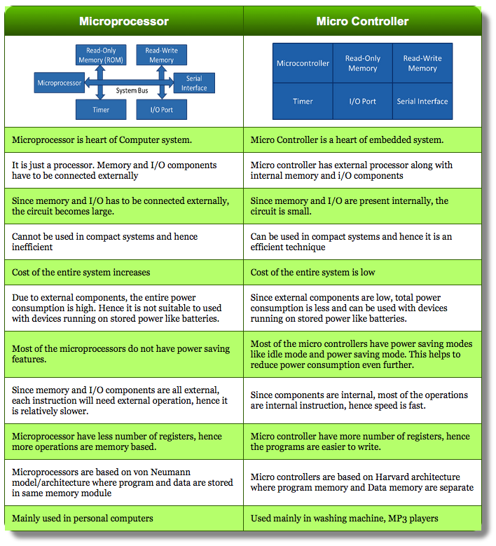
References - https://www.sigmdel.ca/michel/ha/rpi/domo_02_en.html - https://en.wikipedia.org/wiki/Raspberry_Pi - http://fabacademy.org/2019/labs/berytech/Embedded_Programming.html - https://www.riscosopen.org/content/downloads/raspberry-pi - https://www.raspberrypi.org/
-
see this video of Ben Eater om you tube, that shows how registers interact with a 8-bit BUS ↩
-
see pages in this sequence: datasheet ATtiny44, p.53, them, p.67, them p.266 (find PortB on hte list table) ↩
-
http://history-computer.com/ModernComputer/thinkers/Boole.html ↩