8. Computer controlled machining
assignments for this week
- group assignment: test runout, alignment, speeds, feeds, and toolpaths for your machine
- individual assignment: make something big
Summary
I started by using the Slicer for Fusion 360, getting to know the features and the outcames, and studying the plans. Since for machining there is a need for thicker structures in order to have proper pressfit, I had to increase the walls of my design.
In this week I use the facilities at the EDP FAB LAB and the knowledge of the head manager, Paulo Teixeira, and the colaborator, Nuno Calado. At this Fab Lab, I had the opportunity to get to known the RHINO software CAM feature and studying all the parameters, steps to get the machine going. We discuss also the security details as well as maintenance and milling tools characteristics: forms, flutes and dimensions. We test the machine for circular and square fit, round paths and angles as well as cut and pocket diferences cut. We use the Ouplan 2000 CNC machine. We also tested the alignments, speeds, feeds and toolpaths fot this machine. The workshop overall view:

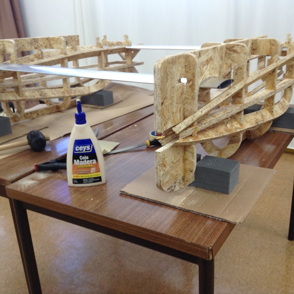
For this week, the big thing I want to built is a hull of the catamaran. This will serve for the first prototype to test the electronics parts and to simulate the integration of the motors with the structure. Along side of this, there will be two students of mine working together with me in this first prototype, Guilherme and Ricardo: they are students at ESCO, a local professional school.

The best fit to use this machine with OSB and Rhino cam is: Equilibrium settings for OSB CNC cutting: Bit: Tungsten Carbide Bit; Feed: 400 mm/min Speed: 18000 (minimum rotation for this machine) Mixed: climb and conventional Passages: 5
Todo
- finish the testing
- Complete the tool parameters
- finish the hulls milling
- Cutting and milling concepts description
- Cutting quality equilibrium
- Missing picture of the boat hulls results [ ] Complete the linear measurements results
- Testing the Fusion CAM
Work done
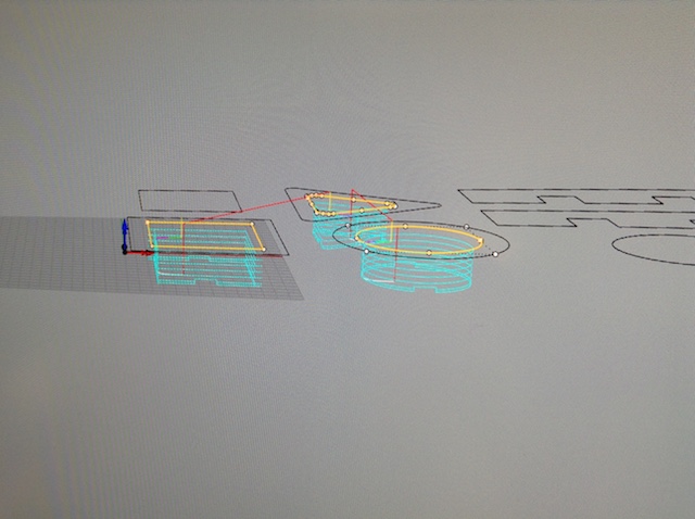
Software Slice for Fusion 360
I start to use the Slice of FUSION 360 and get this:

The workflow with Fusion 360 slicer required some basic notes (meaning what I have used), on the pictures bellow:
- Menu

- Slicing Directions

- Getting the plans

-
Closer look to the plans: the error was important, because the pressfits weer so thiker taht teh structure should collapse easily. So, there was the need to go back and rebuilt the design by inreasing the waals with 30 mm using the design shell tool.
-
With the design ready I get the plans from the slicer:
-
Now its time for the CAM software, to get the GCODE for the milling machine.
-
Before doing this there is a fundamental need to see a few items:
- A. SECURITY
- B. Milling tool characteristics and features
- C. Feeds and speeds
- D. CAM software (RHINO CAM)
Danger

Security first 1
- No loose clothes!!!
- No loose air!!!
- Never use the machine Alone!!!
- Don’t EVER leave the machine unattended
- Simulate how to stop the machine: you and your mate.
- Use non-inflatable clothes
- Use ear protective for HIGH frequencies

- Use gloves (don’t pass with the hand over the milling tool)
- Use glasses
- Y AXIS clear path movement:
![]()
more about security here
- Preparing the machine to cut:
Secure the OSB Board (see up: Y AXIS clear path movement)

Sacrifice plate:

Milling tools specifications
Types of milling tools were discussed, flutes and shapes, and other important concepts:

After choosing the milling tool:

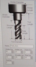
and measuring it,
Info
Flute: 1; Form: helicoidal; Top: not plane; Diameter: 6 mm; Holder Diameter: 32 mm; Holder Lenght: Shank Diameter: tool lenght: Shoulder lenght: Flute lenght:

The two main parameters are feedrate and Spindle Speed. The first is the feed rate which is the speed at which the cutter engages the part and as units of a velocity, m/s, international units. This parameter is very important for the optimization of the cutting and to improve the lifetime of the machine (see this reference for detailed explanation). The second, is the sindle speed rpm units (rotation per minute).
We found a reference at the wikipedia Speeds and feeds for the speeds and feeds, we get this in account, as well as this other one at make magazine, CNC Routing Basics: Toolpaths and Feeds ‘n Speeds. The FAB ACADEMY 2017 student João Milheiro discuss in is week 7 assignment highlight same crucial concepts and gave clues to define this important parameters for a 4 mm milling tool. We use his numbers as a reference, as well as the software for this particular issue.
There two ways for the tool path: conventional and climb. Both as drawbacks as well as advantages. So, the idea is to use both as a strategy when routing. Sounds good! For more about this, see the reference bellow in this page.

About tools, there four main types:
| Tools types | Chipload | all around bit | Notes | plywood or laminated sheet goods |
|---|---|---|---|---|
| straight Flute | decent | great | ||
| Up Spiral | great | can tear-out the top of thin veneer | ||
| Down Spiral | poor | no tear out | slower feed rate | |
| Compression | decent | great | combination of up and down spiral | great |

That all will be tested:

Forms and flutes, types of milling tools:
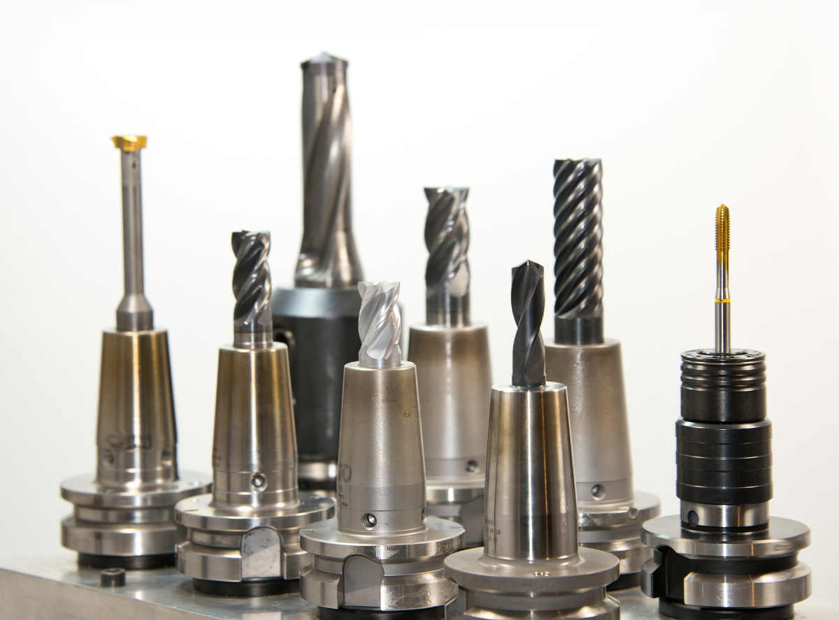
The tools can have a straitgh or helicoidal flutes. The number of flutes can also change as well as the end mill form. There are some important manufacturing enterprises with hig quality tools in Portugal: FREZITE and AFIPRE.
Dimensions (measuring)
Feeds and speeds
We also use this reference of David Selles, at MIT classes MAS.863, from harvard, where he uses also another tool that looks promissing, and we read is work in order to decide what speeds and feeds to use:  .
.
Feedrate = 50 ipm (inches/minute) Speed = 16000 rpm (rotation/minute)
The tool should enter in the part in a ramp movement, where it will pludge down, approach to the part, engage in the part material, cut it, retract when finished and departure after the job done.
There other parameters that we have to decide about: plundge, approach, engage, cut, retract and departure. They are showed here in detail:
There another important step for the gcode process which is the profilling: see bellow.
Reference: Feeds and speeds cook book
Milling procedure
Info
Machine specifications: ER32 Drill chuck, 5 HP, trifasic. The spindle as clockwise rotations and is controlled by Variable-frequency drive: 300 Hz means 18000 RPM.

Put the milling tool in the machine, secure the OSB to the machine
-
Step 0: adjust the reference with the machine software. 1
-
Step 1: check the design dimensions
-
Step 3: Cutting air
start by making the drawing on the air (choose a high z zero)
- Step 2: square it!
Start by doing a square to see the machine behavior. We did also other structures to test round paths and circular and square fit.
Step 4: follow the precise specifications for the machine procedure
Each machine as its own control board, so there is a need to know the software specifications to control de machine.
Source: to use the OUPLAN machine I follow he steps of Toni Barreiros from the Fab Academy 2017, since he also use this machine for is week 7 assignment.
Group assignment
Before preparing the machine there is a need to get the proper names here for this type of CNC milling machines. We prepared the OSB at the machine table:

We tested two tools with this parameters (see picture just bellow this table):
| Parameters | Tool 2 | Tool 3 |
|---|---|---|
| Material | SWC HSS | |
| Tool diameter | 8 | |
| Shank diameter | 8 | |
| Holder diameter | 8 | |
| Holder Length | 20 | |
| Shoulder length | ||
| Flute length | 32 | |
| tool length: | 82 | |
| Flutes | 2 | |
| Form | Helicoidal | |
| Top | plain | Plain |
| Cutting | Conventional | Conventional |
| Feed | 23.6 ipm (600 mm/min ) | 23.6 ipm (600 mm/min) |
| Speed | 18 000 rpm | 23.6 ipm (600 mm/min) |
| Results | Bad sound, didn’t finnished the work, stuck in the object 2 | Good sound, small is better |
Note
Total tool length = Tool length + Holder Length Flute Length < shoulder length < Tool length
Tool working, with a bad and a good sound. See if the conventional is better than the climb movement for the quality finnishing of the cut. I think its better the conventional in this case.
Rhino CAM
All this setup procedure means profilling and cheking the feeds and speeds as well as to get a gcode file which is a file with instructions like this. We used the workflow proposed by the Rhino Cam software.

Testing the machine with this basic geometries, not only to calibration but also to see how they fit:

The two “jobs” defined by the CAM software are here:

The test simulation:

Results
Design Testing at RHINO:

Test results resume:

For the results you can check this table and see the picture bellow.
| tests | Test 1 | test 2 |
|---|---|---|
| Tolerance Press Fit | 0.2 - 0.3 - 0.4 mm | 0.5 - 1 - 1.5 mm |
| Tool number | 2 | 3 |
| Linear mesurements in the software | ||
| Linear mesurements in the software | ||
| Press fit | loose | really tight at 1 mm |
| Shapes Press fit (circular) | didn’t fit | fit tight, it can’t be removed easily |
| Shapes Press fit (square) | didn’t fit | fit tight, it can’t be removed easily |
| Shapes Press fit (triangular) | didn’t fit | didn’t fit |
The team:

Removing the parts,

Wrong turn, solution: wood glue! Same “holes” still too thin.

The pieces, already prepared for the assembly…

The assembly result (to be continued)
Parts:


Glueing:


Hulls:


Final:
Design files
References
-
The zero reference was a serious issue. We found that, this machine just work with this point marked on the bottom of the machine, just on the machine plate. ↩↩
-
the tool was stuck in the object because, we think, we had problems in finding the right zero reference. We were referencing it at the top of the material but it should be at the bottom of the material, in the machine table. So, in the first time the tool enter with a lot of speed inside the object. We stoped the machine suddendly. Well, this cause a great stress on the tool along with the fact that its a long tool. After we define a new zero reference, the tool vibrates and cause a bad sound (see the first video). And after a while it went stuck in the material. ↩