12. Output devices
assignments for this week
- Individual: add an output device to a microcontroller board you’ve designed, and program it to do something
- group assignment: measure the power consumption of an output device
Summary
I add a DC motor to the ATtiny44 microntoler chip and programmed just to drive the motors back and forward. The idea is to reach the limits of this IC to see if it is possible to control the boat motors. I’m planning also to control two DC motors up to 20A and also one solenoid with the water detector of week 11 PCB. This work will be part of future assignments in the upcoming weeks.
For the group assignment we used the power station to measure the consumption of one tiny DC motor: a little more then 1 W.
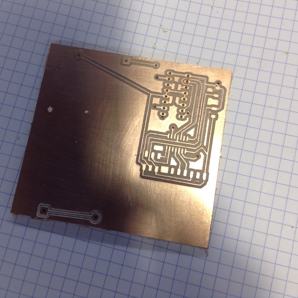
This was the first time using drills on the PCB, since I need to use wires in PCB back. There is a need to type one line of code to Flatcam read the Eagle Trailling zeros.
I did a revisiting of Neil week 11 lecture about input devices and documented it on the same week 11 page.
Same part of the work I didn’t finnished because they used material that was obsolete.
I did the test with the DC motor controll using arduino board and the solenoid controled by the ATtiny44.
All the files are here and at my personal google drive here.
Todo
- review week 11 Neil lecture “Input devices”: documented at week 11;
- schematics drive one solenoid PCB
- Include the link of the scalling issue code used in FLATCAM
- Milling machine Bed flatening procedure
- Greek letters site ARITMATTEX/LATEX here
- video of the solenoid output
- How to write a link to download a file on markdown
- make a IC two dc motors control up to 20 A, with four pins (or more) available
- Issue: ProgressBar extension doesn’t work link
- Issue about the site: gitlab not updated with atom content
- Issue: Browser site updated only when clearing the cookies
Work done
DC motor
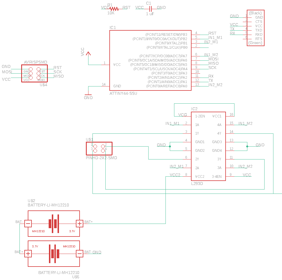
I decided to use the old L293D IC driver to control two DC 6V small motors. First I tested it in an breadboard with an Arduino uno. Reading the datasheet and this tutorial, I found that I need four pins for PWM but I only have three at the ATtiny44. It worked out but there was a need to use only two PWM pins.
Later on I read the documentation of Heidi Hartikainen about his final DC motor project robotic.
IMG_3980 from António on Vimeo.
I found this pinout picture that helped a lot:

And the functional table:
| pins | Logic | Logic |
|---|---|---|
| input 1 | 1 | 0 |
| input 2 | 0 | 1 |
| direction | CW | CCW |
So, for only one DC motor the idea is to control the velocity using the PWM as usual, but to use a second one, including the direction control, I will use the counterpart of the PWM function, when the pin is LOW (zero
This code was use to test the DC control.
// Arduino DC motor speed and direction control

//#define button   8
//#define pot      0
#define pwm1     9
#define dir    10

//boolean motor_dir = 0;
//int motor_speed;

void setup() {
  //pinMode(button, INPUT_PULLUP);
  Serial.begin(9600);
  pinMode(pwm1,   OUTPUT);
  pinMode(dir,   OUTPUT);
}

void loop() {
  //motor_speed = analogRead(pot) / 4;
    analogWrite(pwm1, 50);
    digitalWrite(dir, LOW);
    Serial.println("direção 1");
    delay(3000);
    analogWrite(pwm1, 0);
    Serial.println("para");
    delay(3000);
    analogWrite(pwm1, 200);
    digitalWrite(dir, HIGH);
    Serial.println("direção 2");
    delay(6000);
    analogWrite(pwm1, 0);
    digitalWrite(dir, LOW);
    Serial.println("para");
    delay(2000);
}
Schematics
I use the calculator to check the width traces. The DC motors work at 330 mA so there is no need to worry about the tickness of the paths because 0.4 is more then enougth. The schematics goes like this:
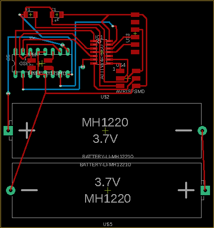
PCB DC motor
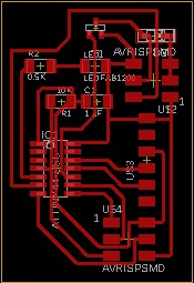
The error here is obvious, I shouldn’t use so much space with copper. But it looks good.
Tools
This is the first time I use the drill for the PCB. This process is well documented at FLATCAM website. The bit in the middle is the drill one.
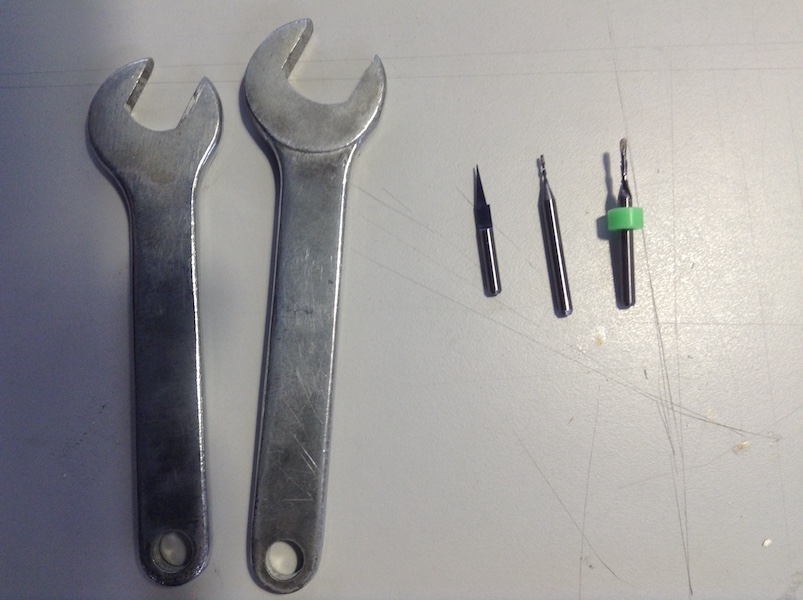
For drilling I used excellon that you can find in the files saved from EAGLE after finnishing your PCB design.
It works fine but, I did same changings to the original Eagle design with Filipe feedback on same errors detected: mainly routes that were to close together where the tool didn’t pass. Also, using the file “drill.xln”, Filipe manage to find same errors in the drilling process, the holes were not correctly scaled from the Gerbers: solved using this code in FLATCAM.
Follow this procedure: For the drilling of the Gerbalino PCB there is a need to adjust the Eagle file to the Flatcam. This is because “Eagle uses Trailing Zeros in its Excellon number format but does not properly report this format in the Excellon file. To tell FlatCAM to use this format by default do this: - Open the comand line in the menu, selecting Tool and clicking on the command line; - It will open a window at the bottom; - Write: get_sys excellon_zeros, it will show a message L; - optional: if you want to check type ****set_sys excellon_zeros T**** to T, it will show a message OK; - After this open the excellon file related to the drills.
Source: http://flatcam.org/manual/eaglehowto.html
Info
FLATCAM accepts this types of files: - Gerber: Typically define copper layers in a circuit board. - Excellon: (drill file): Contain drill specifications, size and coordinates. - G-Code: CNC machine instructions for cutting and or drilling. - SVG: Scalable Vector Graphics.
I use easel to make the flatening of the carvey bed. Really easy: - Sign in here - Choose the machine: in my case Carvey; - Cut settings: feed rate: 700 mm/min; Plunge rate: 200 mm/min; - depth: 0.5; - Bit: straight cut 6 mm - You need to change the colete bit and to mount this tool; - Click on “CARVE…” and follow the instructions;
Two DC motors
Install library at Eagle
I found this plug very usefull because its built inside EAGLE: https://www.samacsys.com/.
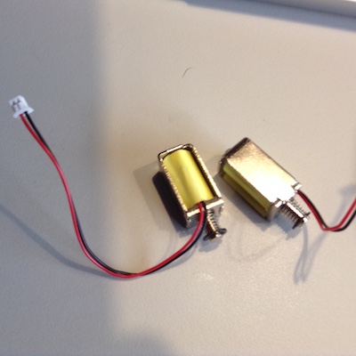
Solenoid
Calcs
The force (All in international units) of an electromagnet is given by:
$$ F = C A n \frac{I}{l} $$,
where C, is a constant ranged from 6,28 to 6,98, A is the solenoid plunger area, n is the number of turns, l, the length of the solenoid and I the current. If the force is enought, then we know the current needed and we can choose the battery voltage:
$$ R = \rho \frac{A’}{L} $$; computing this with Ohm’s Law, V = RI, then we can have the relathionship between, the force and the battery voltage:
$$ F = \frac{C n}{\rho} \frac{A}{A’}\frac{L}{l} $$,
(to be completed)
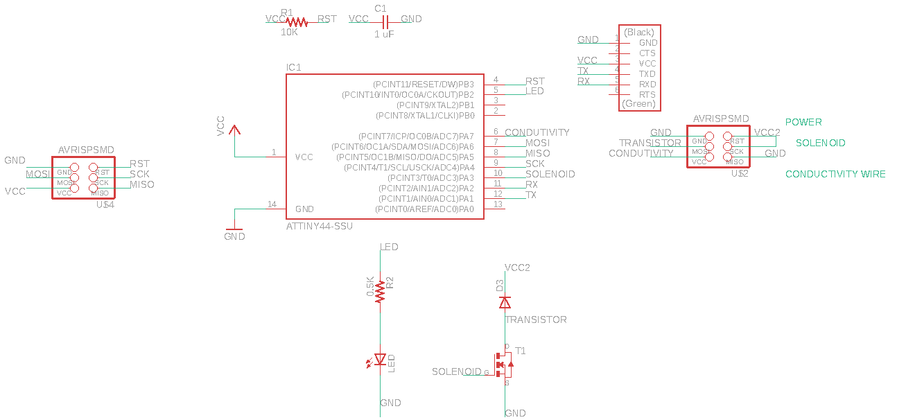
Circuit schematics
Since this is a 12V Micro Solenoid Electromagnet, 120 mA, there is a need for an external power source, but the GND should be common to the ATtiny GND.

Since we have Mr. Faraday and Mr. Lenz working in a solenoid, there is a need to include a diode in order to secure the solenoid for the self induced currents (MIT explained here).
The internal resistance of the solenoid is:
So, according to the Ohm’s Law there is a current of 120 mA at 12V power source.
To drive the solenoid I choose to use a robust transistor, the TIP 120.
In this schematics I put a LED, the possibility of using another input from a another sensor. The external voltage output its possible using auxiliar pins called Vcc2. The other pins are for the conducivity sensor.
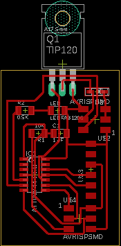
PCB solenoid (last version)
The EAGLE schematics:
The EAGLE board:
The code for ATtiny44 without the interrupt:
//
// Aqua final Fab Academy 2019 project, software for the board at the boat
//to control the inflatable system (water prensence inside the hulls), the solenoid.
//https://www.arduino.cc/reference/en/language/functions/external-interrupts/attachinterrupt/
//Based on this work: https://www.teachmemicro.com/arduino-interrupt-tutorial/
//
// António Gonçalves
// 19/6/2019
//
// (c) Lab Aberto Fab Lab 2019
// This work may be reproduced, modified, distributed,
// performed, and displayed for any purpose. Copyright is
// retained and must be preserved. The work is provided
// as is; no warranty is provided, and users accept all
// liability.

//Sensors
//TX RX comunication
#include <SoftwareSerial.h>
SoftwareSerial Serial(1, 2); // RX, TX, serial for the wifi RN4870

// state
char state;//default state variable, if c, activate servo or solenoid

void setup() {
pinMode(7, INPUT_PULLUP);//condutivity
//digitalWrite(7,HIGH);
pinMode(8, OUTPUT);//LED pin
pinMode(3, OUTPUT);//servo or solenoid
//digitalWrite(servo,LOW);
Serial.begin(9600);
  while (!Serial) {
    ; // wait for serial port to connect. Needed for native USB port only
  }

//pin change interrupt is enabled on the corresponding I/O pin, pin 7 (PCINT7)
//pin 3 react to change with interrupt at pin 7, PCINT7
//SREG = B10000000; //enable interrupts
//GIMSK = B00010000;//p52, when the PCIE0 bit is set (one) and the I-bit in the Status Register (SREG) is set (one), pinchange interrupt 0 is enabled. Any change on any enabled PCINT7:0 pin will cause an interrupt.The corresponding interrupt of Pin Change Interrupt Request is executed from the PCI0 Inter-rupt Vector. PCINT7:0 pins are enabled individually by the PCMSK0 Register
//PCMSK0 = B10000000; //datasheet attiny44, p53, If PCINT7, BIT 7, set to one and the PCIE0 bit in GIMSK is set, any pin change interrupt is enabled on the corresponding I/O pin.

}//ends Setup

void loop() {
  // read the incoming byte:
  state = Serial.read();
  digitalWrite(3,LOW);
  boolean condutivity = digitalRead(7);
  Serial.println(state);
  //Serial.println(inflate);
  //}
  if (state == 'a' || condutivity == HIGH) {
 digitalWrite(8,HIGH);
 digitalWrite(3,LOW);
 Serial.println(F("Inflatable security ready"));
  }
  if (state == 'c' || condutivity == LOW) {
  digitalWrite(8,LOW);
 digitalWrite(3,HIGH);
 Serial.println(F("I'm sinking! Inflatable security enable"));
  }
  /*else if (inflate == LOW){
    digitalWrite(8,HIGH);
   // digitalWrite(servo,LOW);
  //Serial.println(F("Inflatable security ready"));

  }
*/
delay(300);
}//void loop ends

//functions

//interrupt
//ISR(TIM1_COMPA_vect) {//datasheet atiny44 p.48, table 9.1, pin 7 interrupt
//inflate = !inflate;
//}
Video working:
Eagle files and FlatCAM here
The same software but with the interrupt (using registers). The register set on the code is defined by the datasheet at the following pages: ATtiny44, Datasheet register (http://ww1.microchip.com/downloads/en/DeviceDoc/doc8006.pdf): - p.9: SREG register enable interrupt: SREG = 10000000; - p.53: PCMSK0 = B00000100; //enable PCINT2, attiny44 pin 11, arduino pin 2 - p.125, USISR = 10000000; // clear all interrupt flags - p.51, GIMSK = 00100000; //enable PCIE1 group: any change on any enabled PCINT11:8 pin will cause an interrupt. - p.213: register summary.
This is the same software but for the ATmega328p that I will use in the boat software:
//
// Aqua final Fab Academy 2019 project, software for the board at the boat
//to control the inflatable system (water prensence inside the hulls), the solenoid.
//https://www.arduino.cc/reference/en/language/functions/external-interrupts/attachinterrupt/
//
// António Gonçalves
// 19/6/2019
//
// (c) Lab Aberto Fab Lab 2019
// This work may be reproduced, modified, distributed,
// performed, and displayed for any purpose. Copyright is
// retained and must be preserved. The work is provided
// as is; no warranty is provided, and users accept all
// liability.

// state
char state = "b";//default state variable, wifi not listening for the comands from the console, state has its own protocol
  //if c, activate servo,

//Sensors
//TX RX comunication
#include <SoftwareSerial.h>
SoftwareSerial wifiSerial(1, 0); // RX, TX, serial for the wifi RN4870

const byte solenoid = 9;//servo digital pin actuator, pin 13, PB1, atmega328p
volatile byte interruptPin = 8;//12, PB0 atmega328p, pin to detect change with interrupt
volatile byte inflate = LOW;//if HIGH, inflates the security bag

void setup() {
  pinMode(8, INPUT_PULLUP);
  wifiSerial.begin(9600);

//interrupt
//pin 12 react to change with interrupt at pin 12,PB0
   SREG = 10000000; //enable interrupts
   PCMSK0 = B00000001; //enable PCINT0, atmega328p pin 12, arduino pin 8
   PCIFR = B00000000; // clear all interrupt flags
   PCICR = B00000001; // enable PCIE0 group

}//ends Setup

void loop() {
  if (inflate == HIGH) {
  digitalWrite(servo,HIGH);
  wifiSerial.println(F("I'm sinking! Inflatable security enable"));
  }

delay(1000);
}//void loop ends

//functions

//interrupt
ISR(TIMER1_COMPA_vect) {
   inflate = !inflate;

}
Power consumption
Power its an energy (E) flux, defined by $$ P = \frac{E}{time} $$; for the electric energy, it can be calculated measuring the voltage (V) and the current (I) and aplying: P = VI.
In the video you can see, at 0.40 that, in the power source, the voltage is 6.6 V and the current intensity is 0.17 A. So, aplying the later formula you get:
P = 6.6 V x 0.17 A = 1,122 W (watt, international units system)
References
- Force of a electromagnet: https://sciencing.com/calculate-force-electromagnet-5969962.html
- Solenoid: https://en.wikipedia.org/wiki/Electromagnet
- Resistivity: https://en.wikipedia.org/wiki/Electrical_resistivity_and_conductivity
- https://sciencing.com/increase-strength-electromagnet-4461184.html
- https://daycounter.com/Calculators/Magnets/Solenoid-Force-Calculator.phtml
- Heidi Hartikainen, Oulu University, http://fab.academany.org/2018/labs/fablaboulu/students/heidi-hartikainen/finalproject.html
- Attiny programing tutorial: http://highlowtech.org/?p=1695
- Arduino interrupts: https://www.arduino.cc/reference/en/language/functions/external-interrupts/attachinterrupt/
- Code based on this work: https://www.teachmemicro.com/arduino-interrupt-tutorial/
- ATtiny44 pinout: https://42bots.com/tutorials/programming-attiny84-attiny44-with-arduino-uno/
- Markdown: https://www.markdownguide.org/assets/book/markdown-guide.pdf