8. Computer controlled machining
This week’s assignment:
group assignment:
test runout, alignment, speeds, feeds, and toolpaths for your machine
individual assignment:
make something big
Testing our ShopBot
Our Lab is fortunate to have a ShopBot PRSalpha, a full-size CNC machine with a 96”x48” bed. ShopBot Control Software can be downloaded for free here.
Definitions:
- Runout: “rotation inaccuracy which occurs when the tool is no longer aligned with the main axis”
- Alignment: “Straightness”
- Speeds: “Cutting speed (also called surface speed or simply speed) is the speed difference (relative velocity) between the cutting tool and the surface of the workpiece it is operating on”
- Feeds: “Feed rate…is the relative velocity at which the cutter is advanced along the workpiece; its vector is perpendicular to the vector of cutting speed”
- Toolpaths: “a series of coordinate locations that a cutting tool will follow in the machining process”
First, we tested the runout of our 1/4” flat end mill bit by placing it upside down in the collet and tightening the collet loosely. Then, we used a very precise measuring tool to measure the inaccuracy in rotation of the tool, which was within thousandths of an inch.
For alignment and accuracy, we cut a 3”x3” block. The resulting piece measured 3.000”x3.005” with calipers, but for most purposes the 5/1000” inaccuracy on one axis is negligible.
~~We have an existing SOP sheet for speeds & feeds in our Lab, so we did not test that.~~
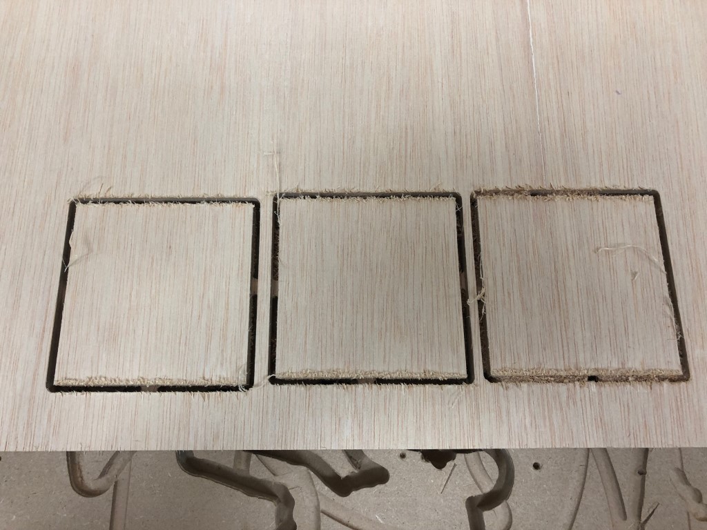
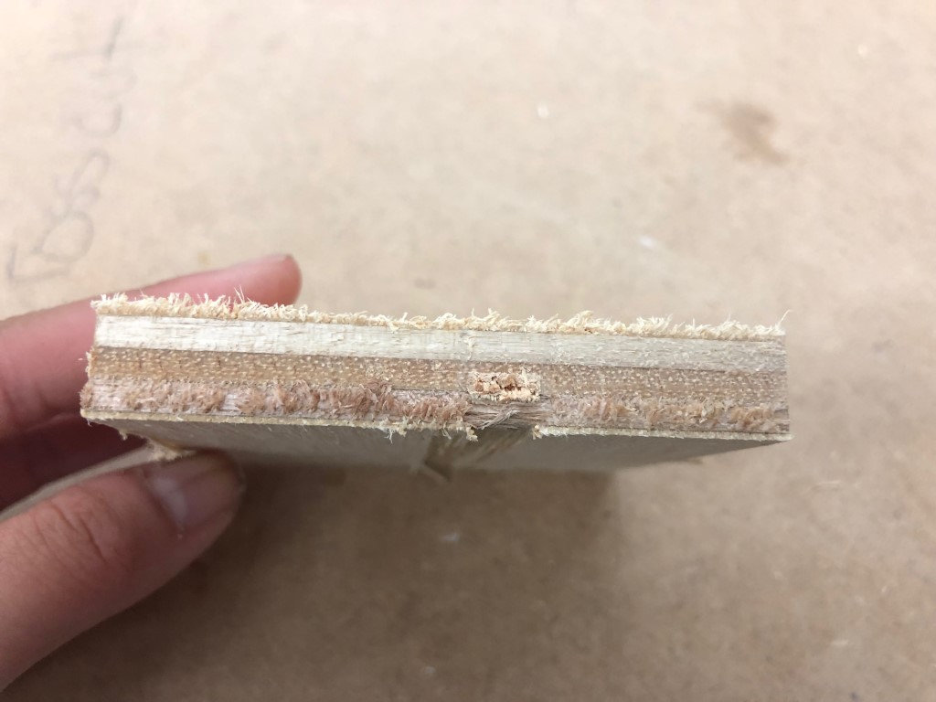
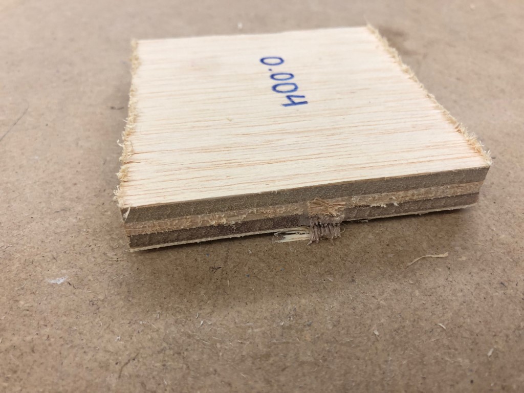
UPDATE (6/20/19): We have experimented with speeds & feeds. Using this chipload calculator, we found a range of acceptable chiploads (and corresponding speeds/feeds) for various materials. We settled on using a 1/8”, 2-fluted bit with plywood on our ShopBot Desktop MAX. The page says that acceptable chipload for this scenario is .004-.006 inches. We then used the calculator on the same page to find three speed/feed combinations to satisfy this requirement. We did test cuts with squares. The cuts and results can be seen below. We could not distinguish any difference between the quality of the resulting cuts, leading us to believe that taking advantage of the higher feeds can save time but result in similar cut quality when within the acceptable chipload.
| Chipload | Speed | Feed |
|---|---|---|
| 0.004” | 18000 | 150 |
| 0.005” | 18000 | 175 |
| 0.006” | 18000 | 200 |
Making Something Big
As I considered my individual assignment for this week, I did a Google search of CNC furniture to find some inspiration.
Eventually, my goal became utility, and I thought about practical items that I could design and produce that would be useful in either my home or our Lab.
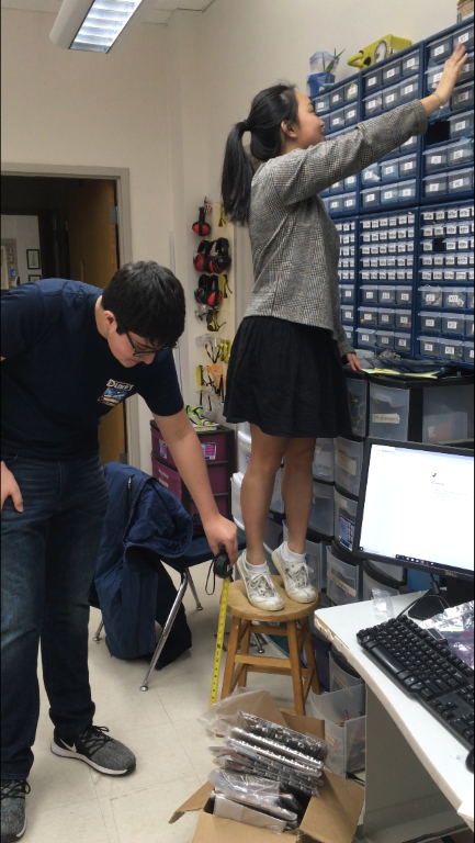
In our lab, we have an inventoried wall of components that extends from above a bank of computers to the ceiling. Often, average-height people have to stretch to reach the top rack, and short people regularly need to stand on a wobbly stool to even reach the middle racks. Maxine, the shortest member of our Fab Academy class, frrequently uses a stool to reach the top. I decided to make a stepladder so that people could safely and easily access any bin on the wall.
I first measured the existing stool to get an idea of how much higher I should make my ladder.
As shown in the above screen-lapse (sped up 1000%), I began parametrically designing a three-step ladder in Fusion, with a tray near the top to hold any bins from the wall. I looked at diagrams here to understand stair standards, like tread width and rise, so that my design would be similar to store-bought stepladders. As I progressed, I added tabs to the steps to make them press-fit with the sides of the stair unit, which is when I realized that I would need to create a test for tab/slot clearance to determine the appropriate dimensions for my slots, which I had yet to add to my design.
Above, a look at my design for the tab clearance test. In the upper left corner is a slot with zero clearance (the dimensions match that of the tab itself), and then each slot afterwards increases in clearance by 2/100 of an inch (0.02”) in length and width, with the bottom right corner slot having a clearance of 10/100 of an inch (0.1”) in length and width. Once I finished the test’s design in Fusion, I created sketches on each body and exported those sketches as DXFs so that I could prepare them for cutting in Aspire. I verfied that the proper dimensions were still in place, and then I rearranged both of the pieces on a 96”x48” workspace to match the space on our ShopBot, making sure that I left 1” margins from the edges of the bed to allow for screws, etc. I had a few difficulties with paths being open, but I was mostly able to solve these with the Join tool in Aspire that closed the paths. I added “dogbone” corners to the vertices of all of the tabs and slots in my design so that they would mate nicely once complete. Then, I created inside profiles for excess material inside of the slots & outside profiles for the parts themselves, adding tabs to keep the cut material secured to the rest of the board until the end of the cut. (I made sure that all of the toolpaths reflected the 1/4” flat end mill bit that I planned on using). Then, I exported ShopBot files for the toolpaths, and followed our Lab’s ShopBot workflow:
Shopbot Cutting using Aspire Toolpath
- Put on eye and ear protection
- Close the doors
- Check to see that the machine has been warmed up
- Check to see bit is not loose
- Use the proximity switch to set Calibrate. (C3 keyboard command)
- Calibrate Z AXIS on the table. (C2 keyboard command)
- Raise Z AXIS 6 inches using the JZ 6 command
- Measure thickness of material that you plan to cut (The thickness of my sheet of material was 0.72”)
- Attach material to the table using screws
- Raise Z AXIS 6 inches using the JZ 6 command
- Start ShopBot Command Console
Conduct air cut
- Select FILE-LOAD
- Load the appropriate file
- Select 1 3-D offset
- Press ENTER
- Turn on the spindle by pressing the big GREEN Button
- You should hear a “SOUND” of the spindle now turning
- Press ok
- After checking that everything is good; press space bar
- Select quit
- Return to origin (M2 0,0)
Perform cut
- Select FILE-LOAD
- Load the appropriate file
- Select no offset rather than 1 3-D offset
- Press enter
- Turn on the spindle by pressing the GREEN Button
- You should hear a “SOUND”
- Turn on the vacuum
- Press enter again to start cut
- Cut is done
- Turn off vacuum (which is so loud you shouldn’t forget)
- Clean up after yourself
Above, a look at my final step ladder design.
I repeated almost the exact same process in Aspire as with the test pieces; once I opened the DXF files in Aspire, I created a pocket toolpath for the pocket in the top shelf, and profile cuts for the rest of the parts. I also followed the same process for using the ShopBot, though I was able to skip the calibration because my original sheet was still on the mill bed from my test cutting.
Above, a timelapse of my ladder components being cut on the ShopBot.
Once my ladder was cut, I removed the components and my board from the ShopBot and sanded down the components. (I used a hammer and chisel to break apart any troublesome tabs) I then used a wooden mallet to fit my components together. I then applied my weight to each of the steps, from the bottom to the top, to ensure that they would hold a person safely. I am a fairly heavy guy, and the ladder held up without any issues. One thing I did notice and received comments on was the lateral stability of the ladder; without any cross-supports, the ladder can sway a little bit to the left and right, and I will have to add some crossbeams to the back of the ladder to mitigate this. However, the ladder does not move forwards and backwards while in use, which is good.
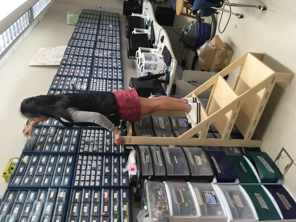
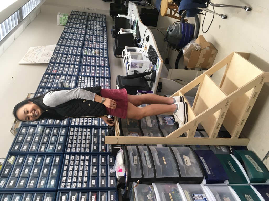
Once I was satisfied that my ladder held my weight without issues, I asked Maxine to give the ladder a try. Above, you can see her reaching a bin on the top row of our parts wall without any problems, and having a great time.
My Design Files (Fusion, DXF, Aspire, and SBP files for the Test & Ladder) (.zip file)