3. Computer Aided design
This week’s assignment:
model (raster, vector, 2D, 3D, render, animate, simulate, …) a possible final project, and post it on your class page
Software
There are many incredible open-source and paid CAD software options on the market today. As a K-12 student, I also have access to free student licenses.
I have experience with SketchUp, Tinkercad, Fusion 360, Inkscape, and CorelDRAW, all of which we use for various purposes at our Fab Lab; I prefer Inkscape & Corel Draw for 2D work and Fusion 360 for 3D work. For this week, I also tried out FreeCAD. However, after looking through some tutorials on their website and speaking with some of my coursemates who had already explored FreeCAD, I realized that it was quite different and less intuitive than Fusion, so I decided to continue using Fusion and learn more about that software throughout this course.
Inkscape
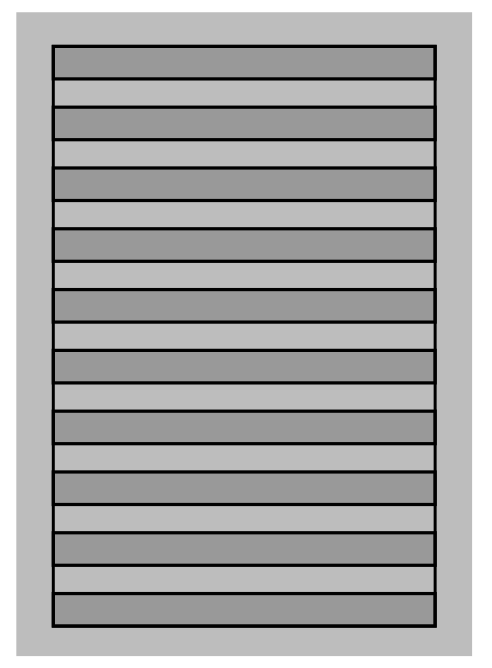
To start, I began designing the louvered side of the weather station; I wanted to create a simple visual representation of the side.
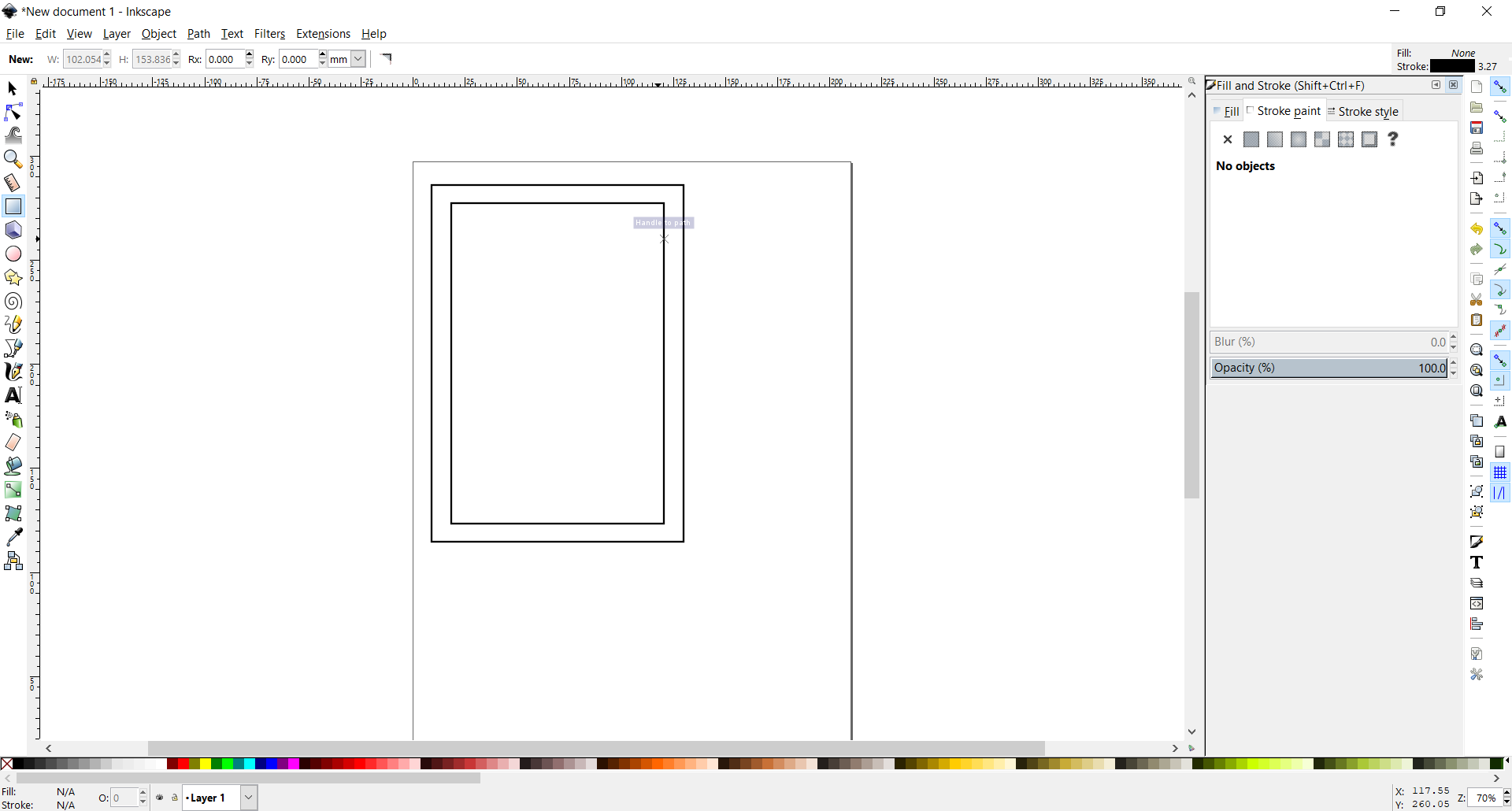
I started by creating the outline of the panel and an inner rectangle to house the vents
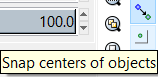
I found the “Snap centers of objects” tool on the right-hand toolbar very useful as it allows me to make concentric shapes
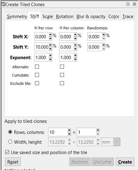
The Tiled Clones menu can be accessed via Edit > Clone in the main (upper) toolbar
This screen recording demonstrates how cloning makes designing very efficient. I was able to edit the color of all of the objects by just editing the master object.
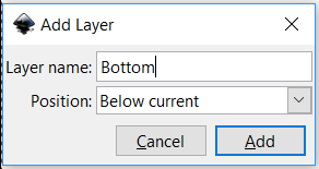
In order to add depth to the design, I tried adding a layer so I could send the outer rectangle to the back, but this did not work. Instead I used a slightly translucent fill to get the desired effect.
Fusion 360
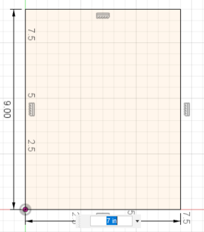
To begin in Fusion, I sketched the backplate in 2D.
I then used the center rectangle tool to create a concentric rectangle for the inside of the enclosure (this later turned out to be unnecessary, as you’ll see in a later step.
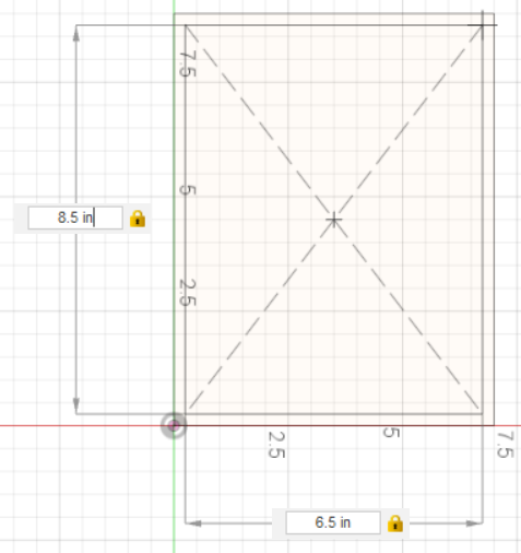
After extruding the larger rectangle to the desired enclosure width, I created a plane at an angle with one of the vertexes at the top of the body.

I then created a sketch on this plane and created a rectangle larger than the top of the body…
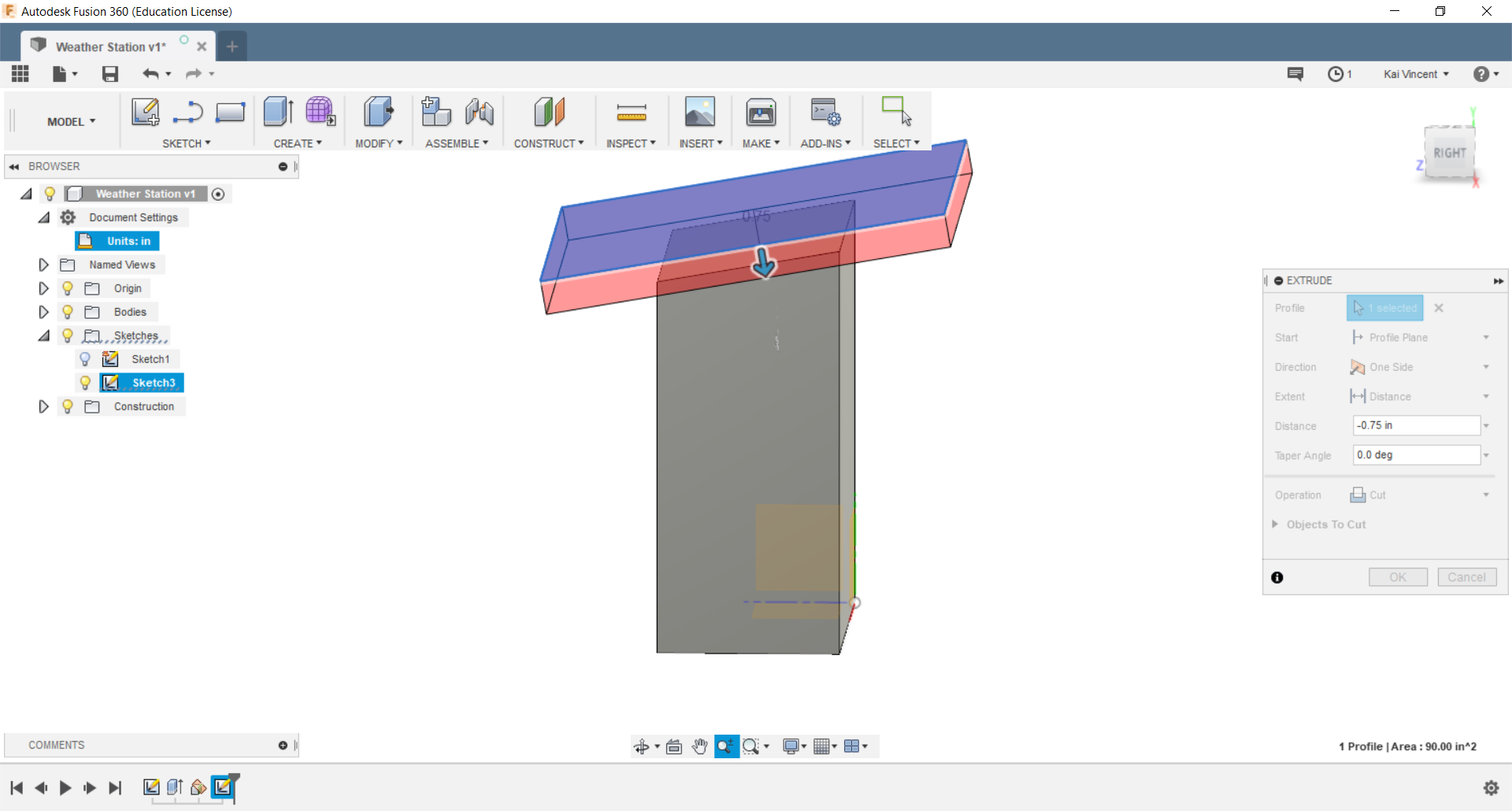
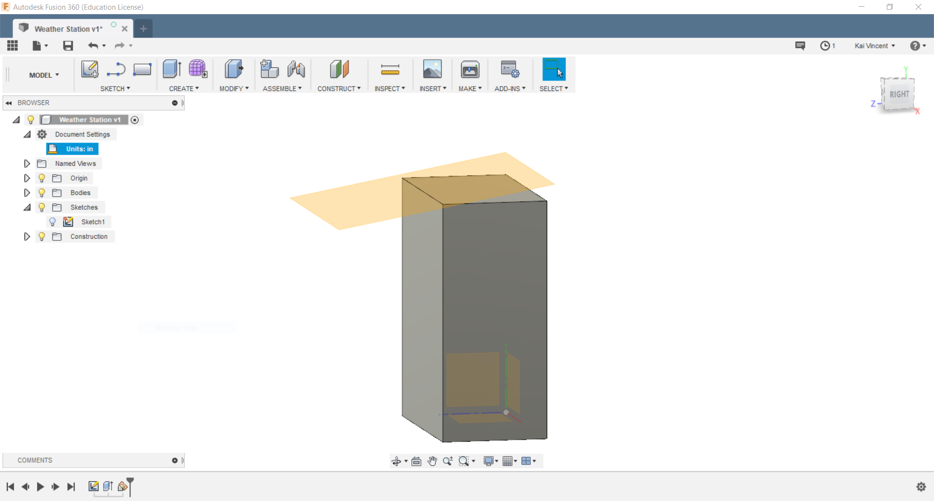
And I cut the first body with this new rectangle to create a sloped roof. Afterwards, I created a new sketch on the front of the enclosure body, drew a rectangle concentric with the front of the body, and cut into the body to create a space for the electronics to be housed within. I also created a rectangle and small circle concentric with the roof and cut space for the solar panel and associated wiring, respectively. Note that this design omits the louvered sides designed in Inkscape (see above) and a front panel due to time constraints. Additionally, all measurements are estimates (see note below).
View of my design history in Fusion; this shows a quick overview of how I designed this basic enclosure.
View of my current Fusion design
Note from future self: I have since learned a vast amount about parametric design in Week 4, and I will certainly implement these findings as I go forward with this final project in the future. For now however, I will keep this rudimentary base design of the housing for reference.
Note from future self #2 (6/21/19): CAD work played a big role in my enclosure designs for my final project. See more about my design work for the enclosures here on my final project page.

Above, a look at a rendering of my outoor enclosure design I made in Fusion.
FreeCAD
UPDATE (6/21/19): I have explored FreeCAD as well. I followed this tutorial to learn basic part design in this open source software. It ended up taking me thirty minutes to just design one simple sketch, extrude it into a body, create a hole in it, and add a fillet to an edge, whereas I could have completed these tasks in a fraction of the time in Fusion (I am admittedly far more experienced in Fusion though). A few notes on my experience:
Pros
- The software is completely free and open source
- It is documented fairly extensively compared to other open source options
- It is very much oriented towards designs with constrints and zero degrees of freedom
Cons
- The program’s orientation towards very specific designs can inhibit more open designs
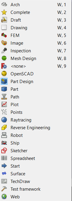
- There are many different “workbenches” that house the various tools and capabilities of the program, making it difficult to easily find the specific tool you need, whereas you find all CAD tools in Fusion in the single main workspace
- The user interface is very barebones and not intuitive at all, requiring new users to pore through many pages of documentation to gain even a faint understanding of the program’s functionalities
Above, a screenlapse of me working in FreeCAD. I followed the aforementioned tutorial and created a test box. As previously mentioned, this fairly simple and unimpressive design took me thirty minutes to complete.