6. 3D Scanning and printing
This week’s assignment:
group assignment:
test the design rules for your 3D printer(s)
individual assignment:
design and 3D print an object (small, few cm3, limited by printer time) that could not be made subtractively
3D scan an object (and optionally print it)
Testing our 3D Printers
Our Lab primarily uses LulzBot‘s Mini 3D printers; we also have a LulzBot Taz for larger prints. We use LulzBot’s Cura software. It imports 3D files such as .STL and .OBJ files and converts them into GCODE for use with the printers, and you can also send the files to print and control the printers from this software.
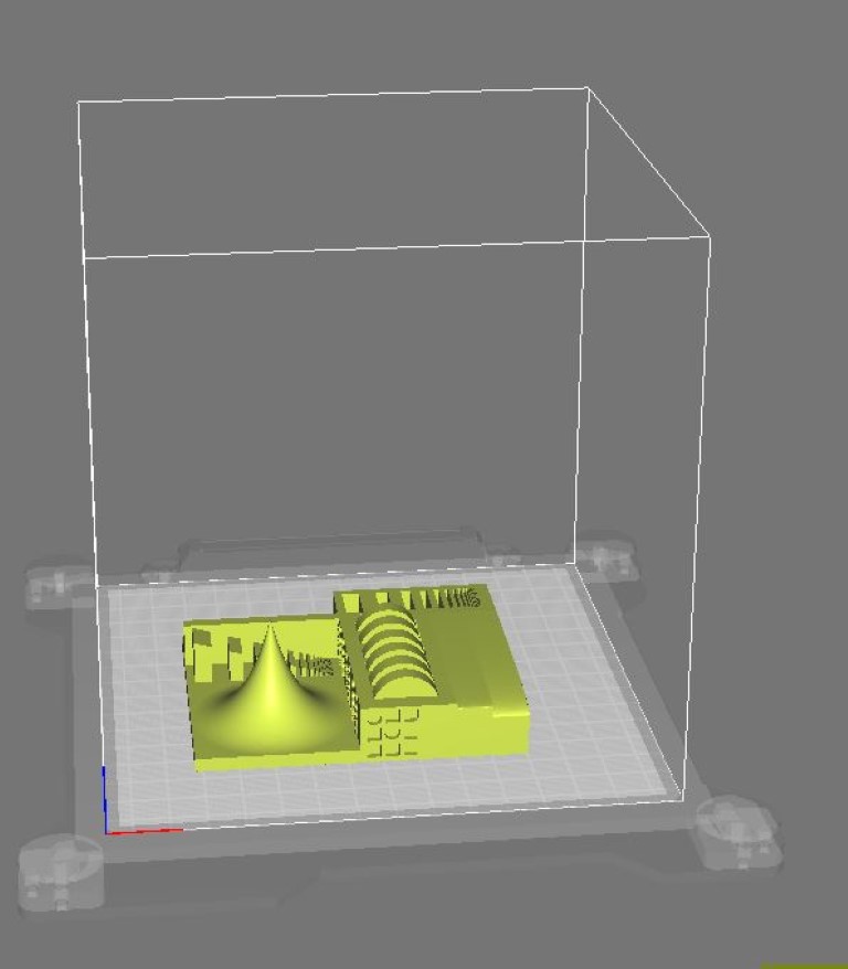
Per Neil’s recommendation, we used the 3D Printer Tolerance Test published by Thingiverse user amandaghassaei (above you can see the TestPrint.stl file that we specifically used).
We follow the following workflow in our Lab when 3D Printing:
Ensure that Lulzbot is on Log on to Computer Retrieve .STL file from Google Drive, etc.
Open CURA Click Load model Select your file
You can view print time Scale and rotate the object to get it to fit and the decrease print time
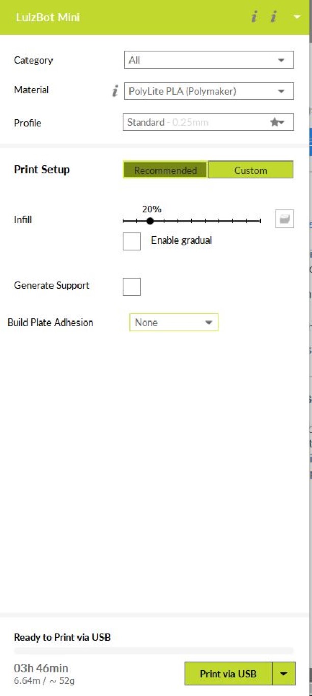
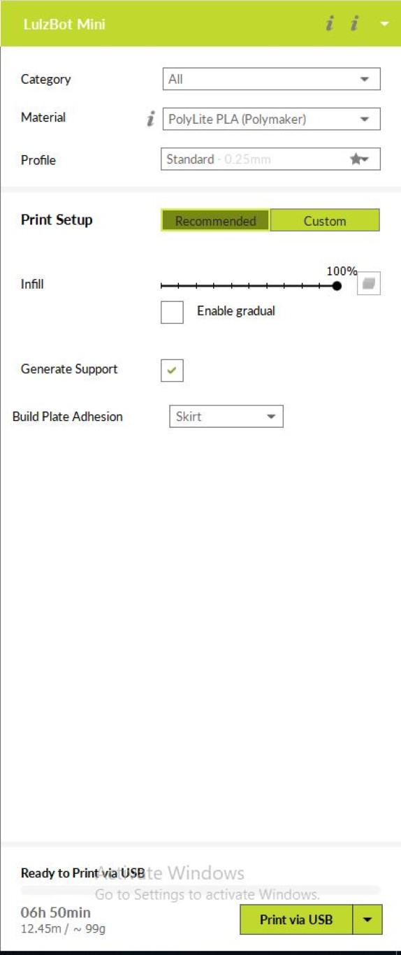
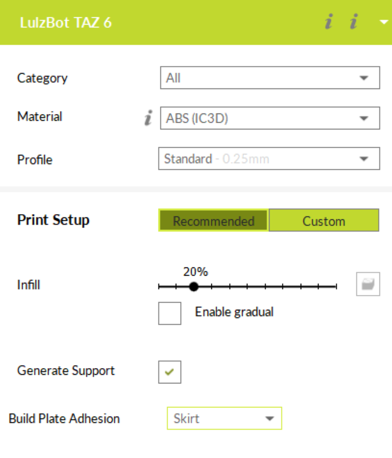
Ensure filament type, speed, etc. is correct (Above photos show material and infill settings used: PLA w/ 20% infill on left, PLA w/ 100% infill in middle, and ABS w/ 20% infill on right) Use support structures for projects with overhangs
Click Arrows To Check If Bed Motors Work (& to make sure that you are controlling the correct printer)
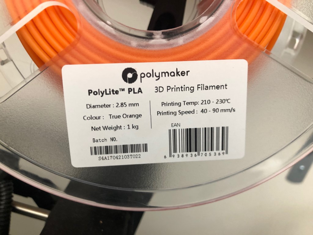
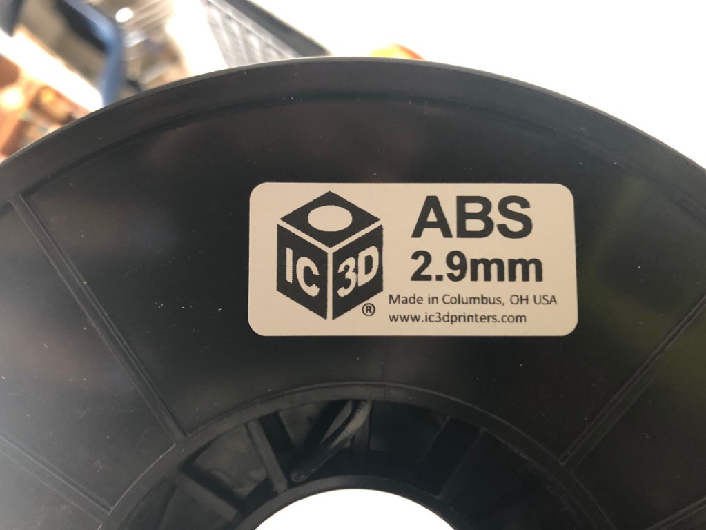
Check recommended print temp on material reel & input into CURA
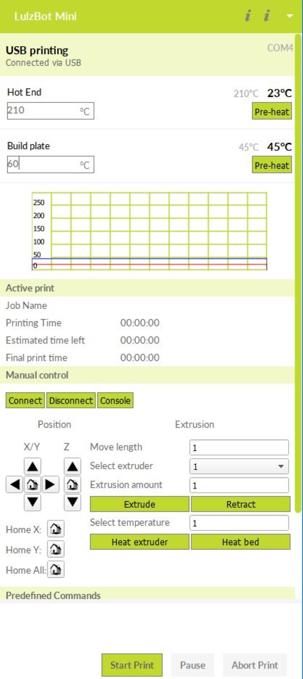
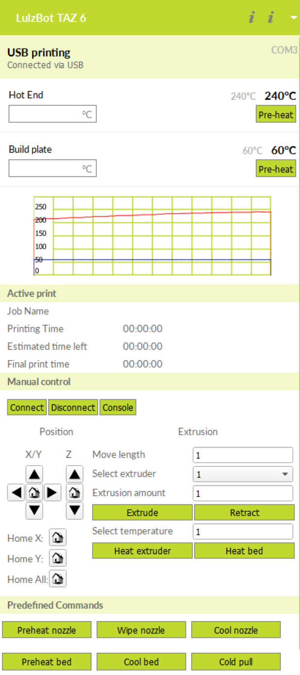
Click Pre-heat (PLA Settings above left, ABS settings above right)
Prepare Bed:
-
Scrape The Bed clean of residue
-
Wipe With Alcohol
-
Brush Nozzle
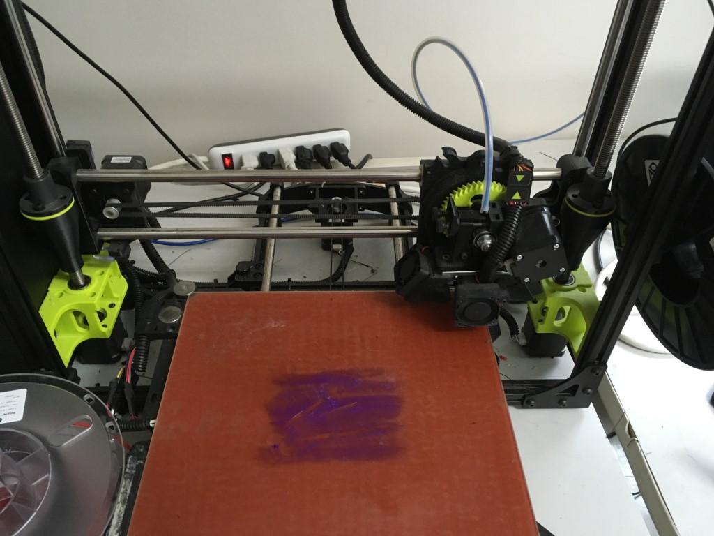
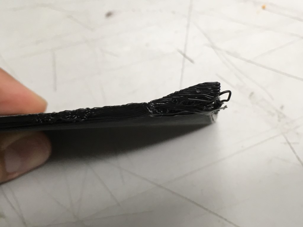
- Apply glue to warmed bed if using ABS so that the print won’t lift off of the bed while printing - an example of an ABS print that lifted off of the bed is above right
Click “Extrude” to make sure that extruder is hot enough. Make sure filament comes out straight. If it is not straight, clean the extruder.
Click Print
Temp Will Go Down and then Re-heat due to software - Don’t Worry
Keep brushing/removing material from nozzle
Make sure to turn off heat once job is complete
The tolerance test in progress on one of the Minis using PLA.
The tolerance test in progress on the Taz using ABS.
Unfortunately, the PC running the Taz froze mid-print for an unknown reason.
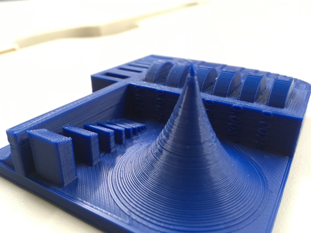
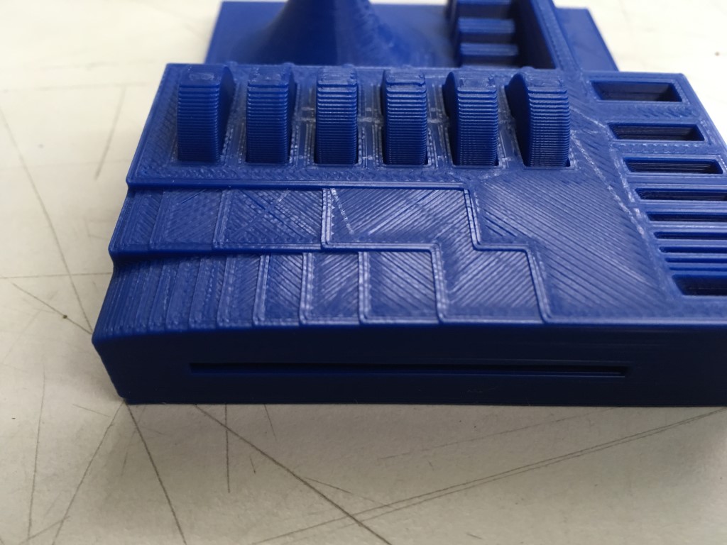
Above, you can see the result of the PLA print that succeeded.
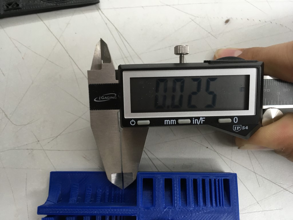
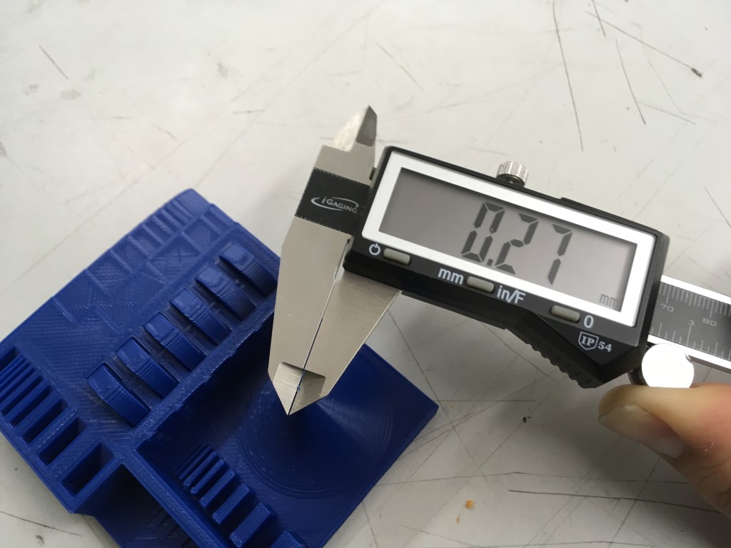
Above, you can see measurements of the thinnest line printed and the thinnest point printed in the tolerance test. The thinnest line was about 0.025 in or 0.635 mm wide, while the thinnest point I could measure on the peak in the middle was about 0.011 in or 0.27 mm wide.
3D Printing
For my 3D print, I decided to ask my sister if she wanted a little trinket; she thought of a little house, and that is what I ended up designing. For this project, I used Fusion. My goal was to test how well our 3D printers could handle overhangs/indents, so I incorporated these with roof overhangs and door/window indents & overhangs. I also incorporated the parametric design rules that I learned in past assignments; when I tried decreasing the size of the house, I realized that I hadn’t placed the windows parametrically with respect to the front of the house, so when I decreased the size of the house, the windows were floating mid-air.
Me designing the house in Fusion (the footage has been sped up x 1000% - it took about 35 minutes to design in reality). You can see me establishing user parameters and utilizing mirror lines to make my life easier.
Update: I realized that I needed to add additional features to the house that would only be possible with additive manufacturing. As such, I opened the doorway and windows, added steps, hollowed out the house, and added a small table inside.
Above, my final design product in Fusion.
Once I had my .STL file from Fusion, I followed the same 3D printing workflow outlined above. I decided to print the house right side up so that the table inside would print well without supports.
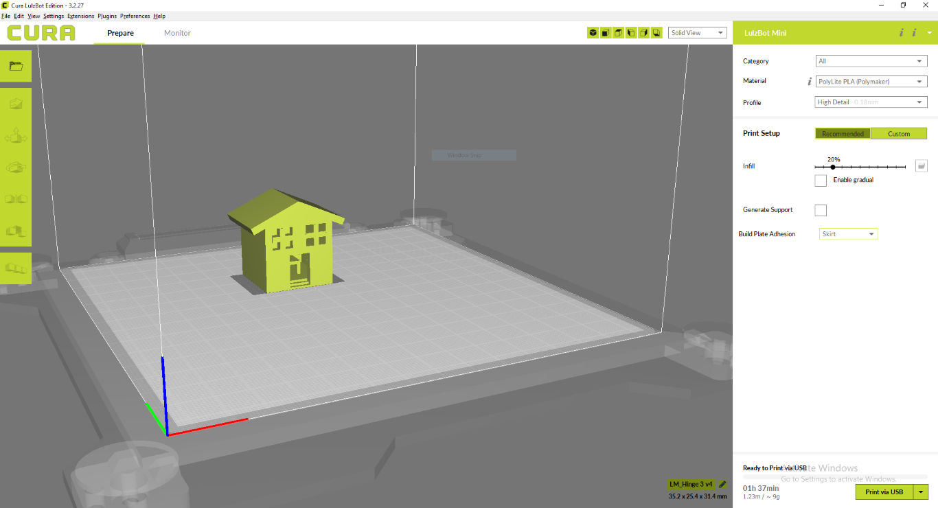
A look at the settings I used for my final print (note that I have supports turned off - I used a skirt build plate adhesion)
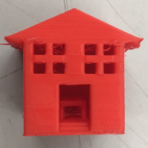
The final product, looking at the front. See the little table inside?
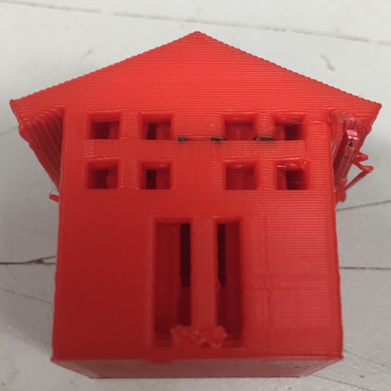
Note: One issue I experienced was with using supports. I initially used supports in order to support the roof, but this meant that there were also supports inside the house (as seen above), which I did not want. I tried printing without supports and everything worked perfectly.
3D Scanning
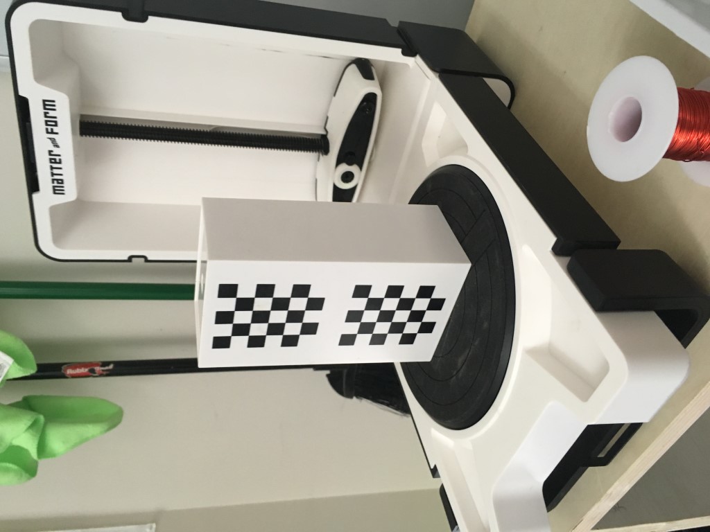
Our Lab has Matter and Form‘s Desktop 3D Scanner (V1). We use their MFStudio software to scan objects and mesh scans.
Because it was my first time using this machine, I did a quick read of the User Manual.
Before you begin scanning, you want to place the calibration block on the scanner bed and open the calibration panel in MFStudio and follow the prompts. This process ensures that the camera and lasers
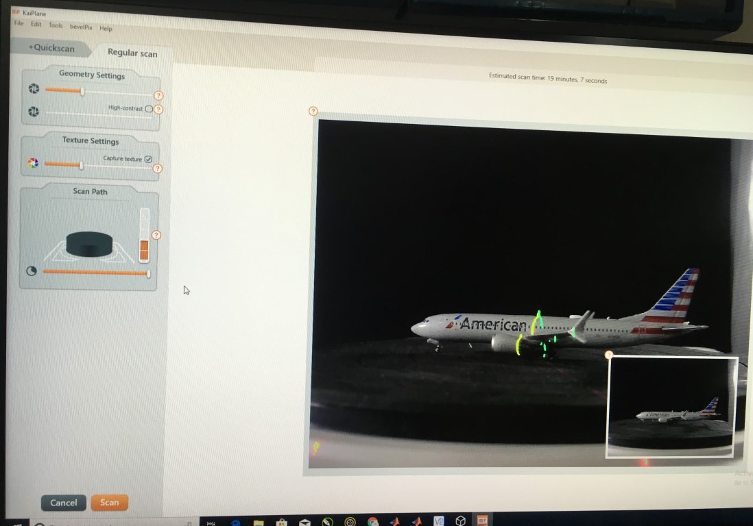
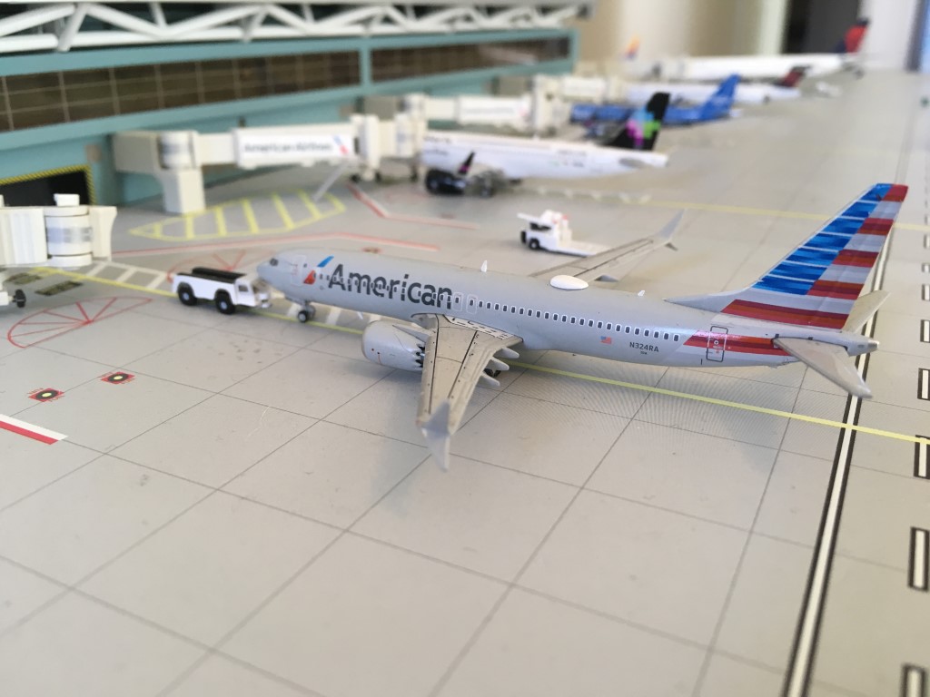
Once I was ready to scan, I took my object, a 1/400 scale American Airlines 737 MAX 8, placed it on the plate, and clicked New scan. Per the manual, I experimented with the exposure settings of the lasers and the camera to get a good picture. Above, you can see the aperture setting screen. The goal is for the lasers to show up as crisp lines on the object in the main image on the screen.
The above video shows the scanner’s plate rotating and camera and lasers moving during one of my scans.
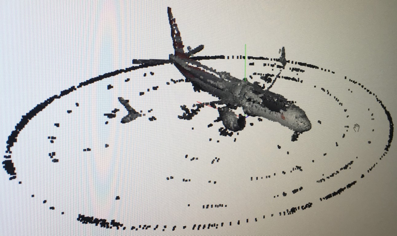
After taking multiple scans (without moving the object being scanned), I had to clean false points off of the scans. To do so, I used the cleaning tool panel on the scans screen to select and remove extraneous points. In the above image, you can see all of the points before I began cleaning, and you can see me cleaning in the video above. Note that the video has been sped up significantly; in reality, cleaning took me over 10 minutes.
Then, I meshed my scans in MFStudio. Note that this footage has been sped up; in reality, each mesh took a few minutes depending on the mesh quality selected. In the video, each mesh is of higher quality than the one before.
Once a mesh of the desired quality is obtained, you can Export a 3D file (e.g. STL, OBJ, etc). Above, you can see my final product, which was a mesh at the highest quality level in MFStudio, in comparison to the actual model plane shown below it. Note how the wings are separated, the vertical & horizontal stabilizers have missing sections, and the aircraft is not smooth for the most part. The scanner we have is on the amateur end of the quality scale; while it does okay with smaller, simpler objects, it does not fare as well with larger or more complex objects like my model plane. If I need to replicate a larger/more complex object in the future, I would have to consider other methods (e.g. molding & casting).
Note: In case we wanted to do multiple scans of a larger object (which can take many hours), I setup a remote desktop connection to the computter running the scanner so that we could control it from home. I used VNC’s Server & Viewer software; their free plan worked perfectly for our needs. I did not use it myself for this assignment as I was able to complete my scans throughout the course of a schoolday, but it could come in handy in the future.