Assignment
individual assignment:
read a microcontroller data sheet,
program your board to do something,
with as many different programming languages
and programming environments as possible
group assignment:
compare the performance and development workflows
for other architectures
Individual Assignment
Introduction
Since I am new in electronics and programming, I will start first by doing some research to understsand the definition of each term used.
What is a Microcontroller?
A microcontroller is a small, low-cost and self contained computer-on-a-chip that can be used as an embedded system.
What does embedded system mean?
An embedded system is a controller programmed and controlled by a real-time operating system with a dedicated function within a larger mechanical or electrical system, often with real-time computing constraints. It is embedded as part of a complete device often including hardware and mechanical parts. (Wikipedia)
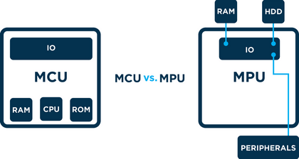
What is the difference between a Microcontroller and a Microprocesssor?
Microcontrollers (MCUs) tend to be less expensive, simpler to set-up, and simpler to operate than microprocessors (MPUs). An MCU can be viewed as a single-chip computer, whereas an MPU has surrounding chips that support various functions like memory, interfaces, and I/O. The MCU vs. MPU question may seem simple, but there are some prominent differences.
One of the main differences between microcontrollers and microprocessors is that a microprocessor will typically run an operating system. An operating system allows multiple processes to run at the same time via multiple threads. Drivers are required to support peripherals.
A microcontroller will run a “bare metal interface,” which means there is not an operating system. Without an operating system, a microcontroller can only run one control loop at a time. From a software perspective, this means a single thread is running on the microcontroller’s processor or Central Processing Unit (CPU).
Types of Microcontollers?
There are many types of Microcontrollers, below are some of them:
- Microcontroller 8051
- Renesas Microcontroller
- PIC Microcontroller
- AVR Microcontroller
For more information on microcontrollers-types-and-applications
In this assignments we will be using an AVR Microcontroller
AVR microcontroller is developed by Alf-Egil Bogen and Vegard Wollan from Atmel Corporation. The AVR microcontrollers are modified harvard RISC architecture with separate memories for data and program and speed of AVR is high when compare to 8051 and PIC. The AVR is stands for Alf-Egil Bogen and Vegard Wollan’s RISC processor.
The figure below gives the basic layout of a general AVR microcontroller:
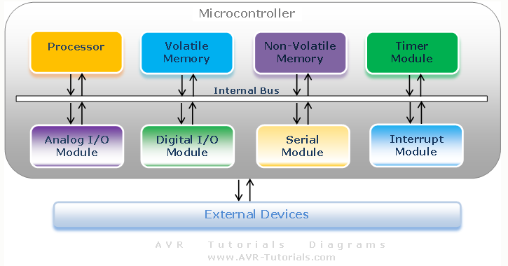
- Processor - The processor refers to the Central Processing Unit (CPU) of the microcontroller. It contains the Arithmetic Logic Unit (ALU), Control Unit, Instruction Decoder and some Special Registers (Stack Pointer, Status Register, Program Counter, etc.).
- Volatile Memory - This is memory used by ht microcontroller for temporary data storage, system setup and peripherals configurations. Memory in this category includes SRAM and DRAM. AVR microcontroller utilize SRAM.
- Non-Volatile Memory - This is memory used by the microcontroller to store programs. Data can also be stored in this memory but the access time is much slower than that of RAM. Memory in this category includes ROM, PROM, EPROM, EEPROM and FLASH. The AVR microcontroller utilize Flash for program storage, some AVR controllers contains a bit of EEPROM as well.
- Timer Module - Most microcontrollers have at least one timer/counter peripheral. Timer/Counter modules are used to perform timing or counting operations in the controller. These include time stamping, measuring intervals, counting events, etc.
- Interrupt Module - Interrupts enable the microcontroller to monitor certain events in the background while executing and application program and react to the event if necessary pausing the original program. This is all coordinated by the interrupt module.
- Digital I/O Module - This module allows digital/logic communication with the microcontroller and the external world. Communication signals are that of TTL or CMOS logic.
- Analog I/O Modules - These modules are use to input/output analog information from/to the external world. Analog modules include Analog Comparators and Analog-to-Digital Converters.
- Serial Modules - These modules are used for serial communication with the external world. An example is the USART peripheral which utilizes the RS232 standard.
In this assignments we will be focusing on Programming the ATtiny44 AVR Microcontroller use on the HELLO BOARD in W7 Electronic Design
ATtiny44 AVR Microcontroller
Based on the Data Sheet below is a Summary
ATtiny44 is a low-power CMOS 8-bit microcontrollers based on the AVR enhanced RISC architecture.
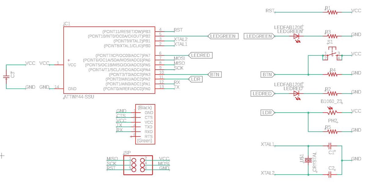
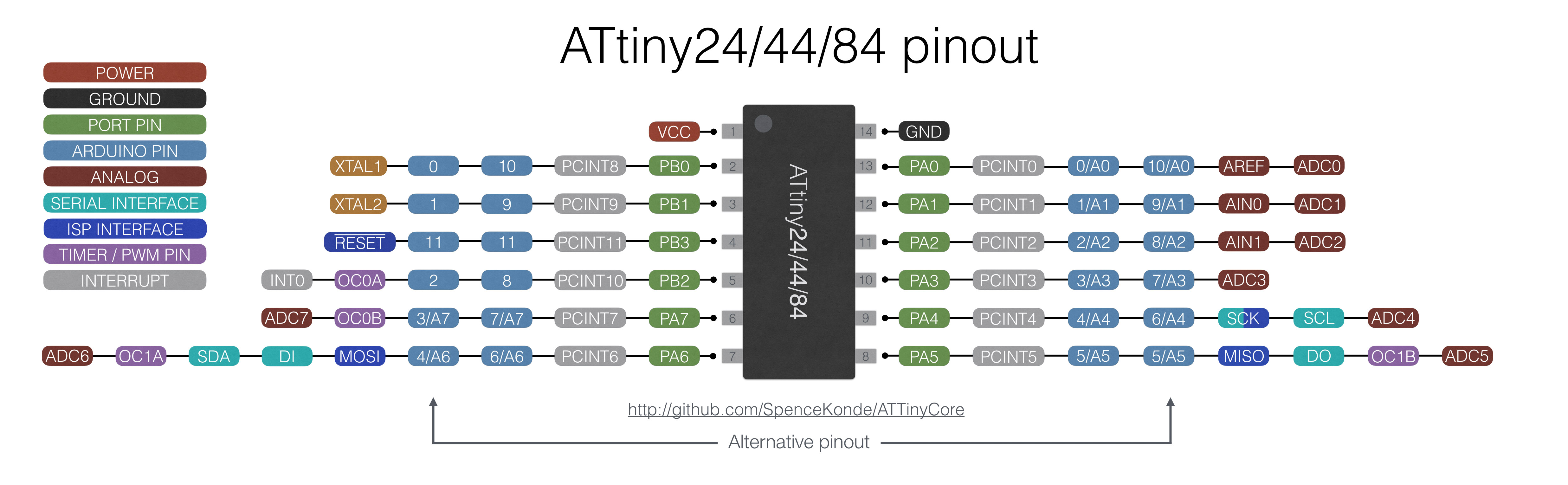
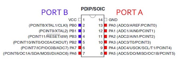
Pin Configuration
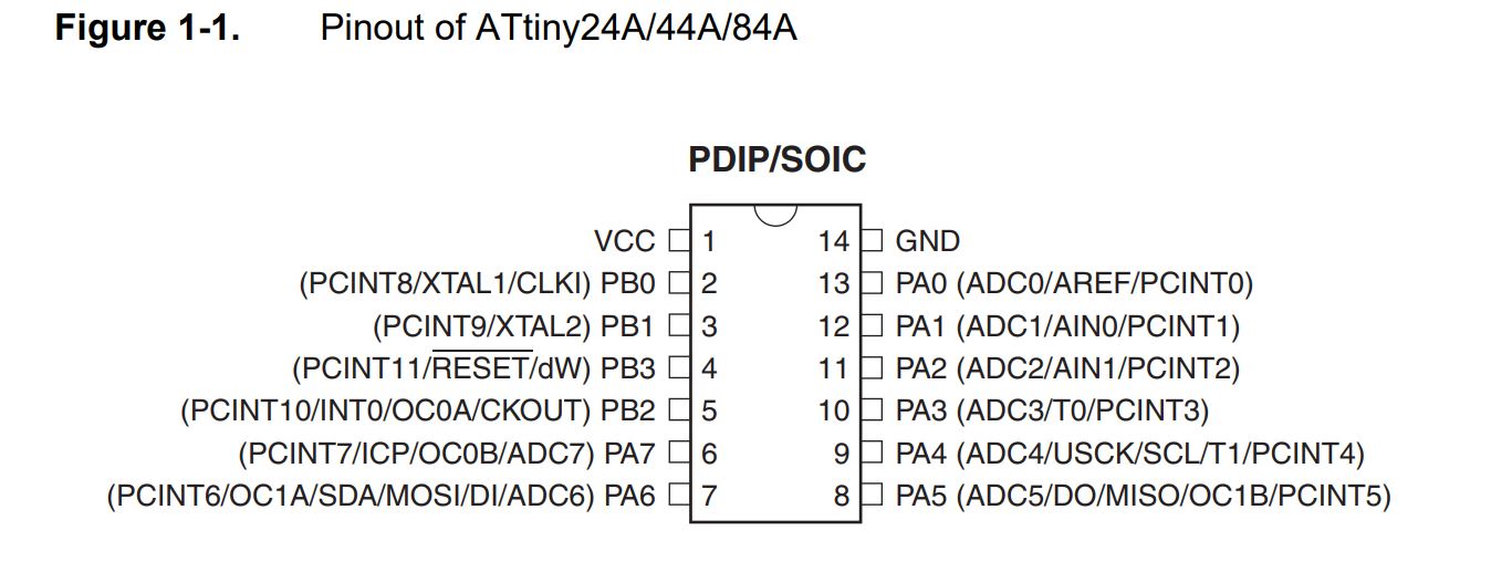
Pin Descriptions
- VCC: Supply voltage
- GND: Ground
- Port B (PB3...PB0): Port B is a 4-bit bi-directional I/O port with internal pull-up resistors (selected for each bit). As inputs, Port B pins that are externally pulled low will source current if the pull-up resistors are activated.so we don't need to add a pull-up resistor externally for button's and other purpose.
- RESET: Reset input. A low level on this pin for longer than the minimum pulse length will generate a reset, even if the clock is not running.a reset will just reset the program that currently running .
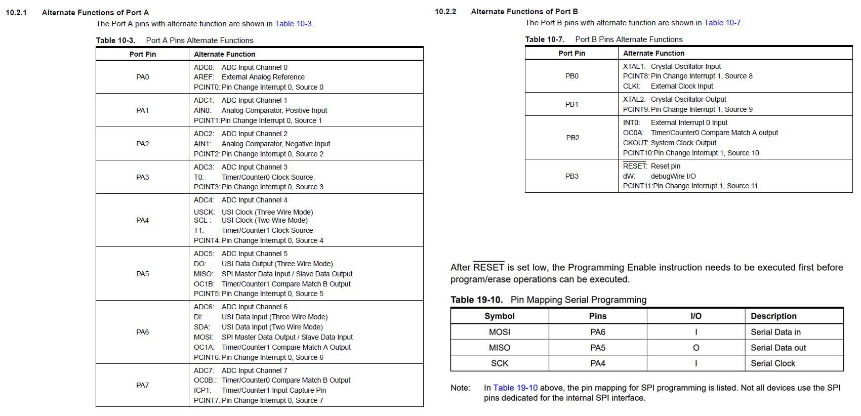
- Port A (PA7...PA0): Port A is a 8-bit bi-directional I/O port with internal pull-up resistors (selected for each bit). As inputs, Port A pins that are externally pulled low will source current if the pull-up resistors are activated
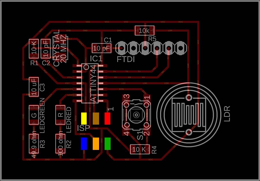
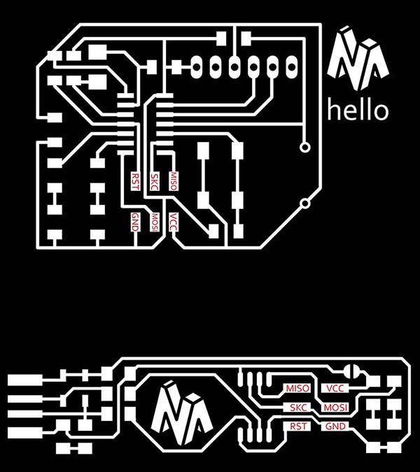
My Hello-Board
Summary
What we can retain from all this is the following:
- Pin1 = VCC / is connected to the supply voltage
- Pin2 = PB0 / is connected to the Crystal
- Pin3 = PB1 / is connected to the Crystal
- Pin4 = PB3 / is connected to the Reset
- Pin5 = PB2 / is used as OUTPUT and connected to the Green Led
- Pin6 = PA7 / is be use as OUTPUT and will be connected to the Red Led
- Pin7 = PA6 / is connected to MOSI
- Pin8 = PA5 / is connected to MISO
- Pin9 = PA4 / is connected to SCK
- Pin10 = PA3 / is used as INPUT and connected to the Button
- Pin11 = PA2 / is used as INPUT and connected to the LDR
- Pin12 = PA1 / is connected to the RX
- Pin13 = PA0 / is connected to the TX
- Pin14 = GND / is connected to the ground
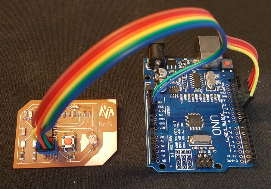
Programming using Arduino
Below is the process showing how to use an Arduino Uno as an In-System Programmer or ISP. An ISP allows AVR microcontrollers to be programmed and reprogrammed without having to remove them from the circuit. Six wires are needed to program any AVR microcontroller. Three of these wires are referred to as the Serial Peripheral Interface (SPI) and are the Master In - Slave Out (MISO), Master Out - Slave In (MOSI), and Serial ClocK (SCK). The "Master" is the ISP or the device you are using to program the AVR chip. The "Slave" is the AVR chip being programmed. The other three wires are for the 5V power supply (VCC), Ground (GND), and Reset (RESET).
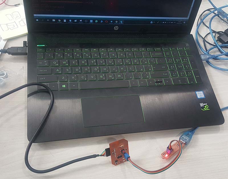
The connection
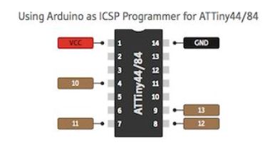
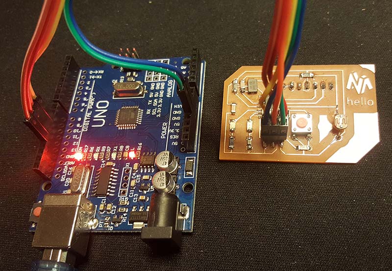
The images above illustrate which pins on the ATtiny correlate to which function when programming them.
- The SCK pin is where the Master provides the clock information for communication
- Every pulse of the SCK pin sends one bit of data over both the MOSI and MISO pins (this is essentially the ATtiny and Arduino communicating back and forth)
- The GND pins of both the Arduino and AVR should be connected to help the chips establish the same reference voltage
- The RESET pin is the channel to which the Arduino is able to erase the contents on the AVR chip and enable serial programming
- The VCC pin is connected to the Arduino simply to remove the need for batteries or external power supplies
When you come to set up your Arduino to act as an ISP, you are basically informing the Arduino how to format the code and over which pins it should send the data.
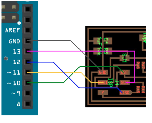
Based on that the connection will be as follow:
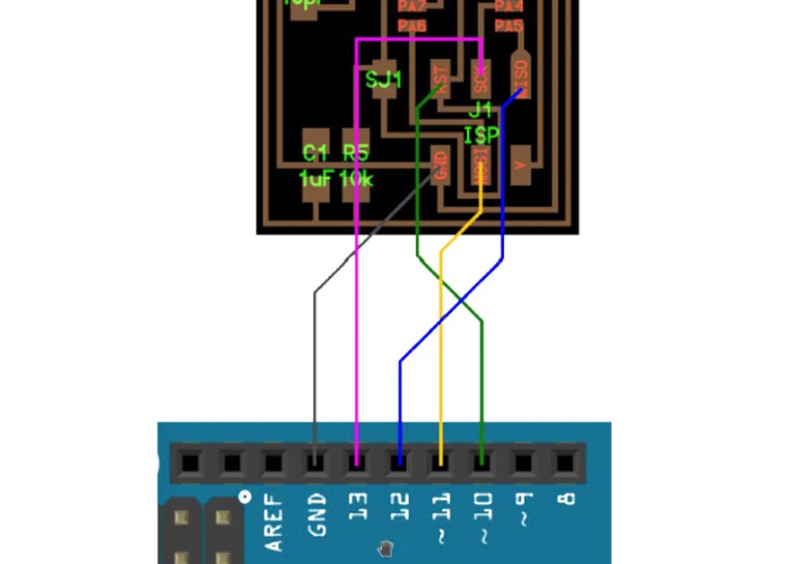
- GND on my board to GND on Arduino (Blue cable)
- RST on my board to Pin 10 on Arduino (Yellow cable)
- MOSI on my board to Pin 11 on Arduino (Orange cable)
- SKC on my board to Pin 13 on Arduino (Brown cable)
- VCC on my board to VCC on Arduino (Green cable)
- MISO on my board to Pin 12 on Arduino (Red cable)
Arduino Setup
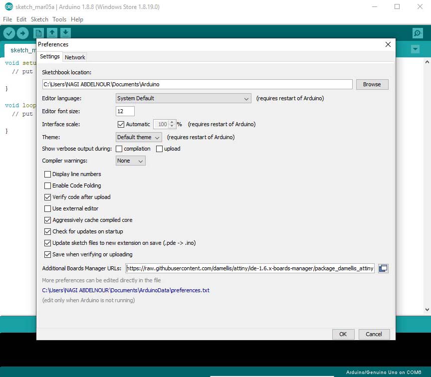
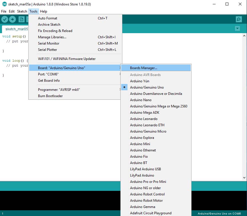
The first thing to do is to install Attiny44 board on the Aruino IDE. For that we go to settings and insert this link: "https://raw.githubusercontent.com/damellis/attiny/ide-1.6.x-boards-manager/package_damellis_attiny_index.json" in the additional board URL then go to tools => boards manager.
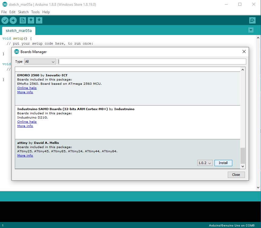
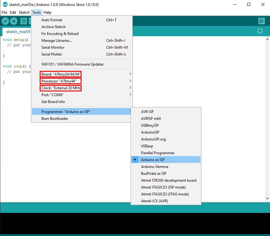
Now we Install Attiny program, then go to tools and set the Board ,the Processor and the Clock of my hello board.
Then set the programmer "Arduino as ISP"(we have to upload the the ISP exemple to arduino before if it's not already uploaded).
And finally remember to go to tool => burn bootloader for the first time I am programing my hello board or when I want to reset it.
Note that the Arduino should be set as ISP and should upload the ArduinoISP code to the Arduino before 'Uploading Using Programmer'.
Programming
- Pin5 is for Green LED in my board and will be Pin8 on Arduino.
- Pin6 is for Red LED in my board and will be Pin7 on Arduino.
- Pin10 is for Push Button in my board and will be Pin3 on Arduino.
- Pin11 is for LDR in my board and will be Pin2 on Arduino.
So I have to enter Arduino pin numbers in the coding.
Programm 1
The 2 leds should light when I push the button and the Leds should turn off when I release the Button with a delay of 2000 milliseconds.
                                // constants won't change. Used here to set a pin number:
                                const int buttonPin = 3;//the number of the pushbutton pin
                                const int ldrPin = 2;//the number of LDR pin
                                const int ledPingreen = 8;// the number of the greenLED pin
                                const int ledPinred = 7;// the number of the redLED pin

                                // Variables will change:
                                int ledState = LOW; // ledState used to set the LED

                                int buttonState = 0;
                                int sensorValue = 0; // variable to store the value coming from the sensor


                                void setup()
                                {
                                // put your setup code here, to run once:
                                // set the digital pin as output:
                                pinMode(ledPingreen, OUTPUT);
                                pinMode(ledPinred, OUTPUT);

                                // set the digital pin as input:
                                pinMode(buttonPin, INPUT);
                                pinMode(ldrPin, INPUT);

                                }

                                void loop()
                                {
                                // read the state of the pushbutton value:
                                buttonState = digitalRead(buttonPin);

                                // check if the pushbutton is pressed. If it is, the buttonState is HIGH:
                                if (buttonState == HIGH)
                                {
                                // put your main code here, to run repeatedly:
                                digitalWrite(ledPingreen, HIGH); // turn the LED on (HIGH is the voltage level)
                                digitalWrite(ledPinred, HIGH); // turn the LED on (HIGH is the voltage level)
                                delay(2000);
                                }
                                else
                                {
                                digitalWrite(ledPingreen, LOW); // turn the LED off by making the voltage LOW
                                digitalWrite(ledPinred, LOW); // turn the LED off by making the voltage LOW
                                }
                                // wait for a second

                                }
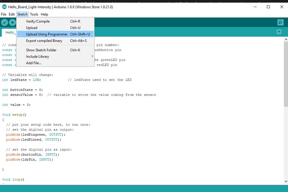
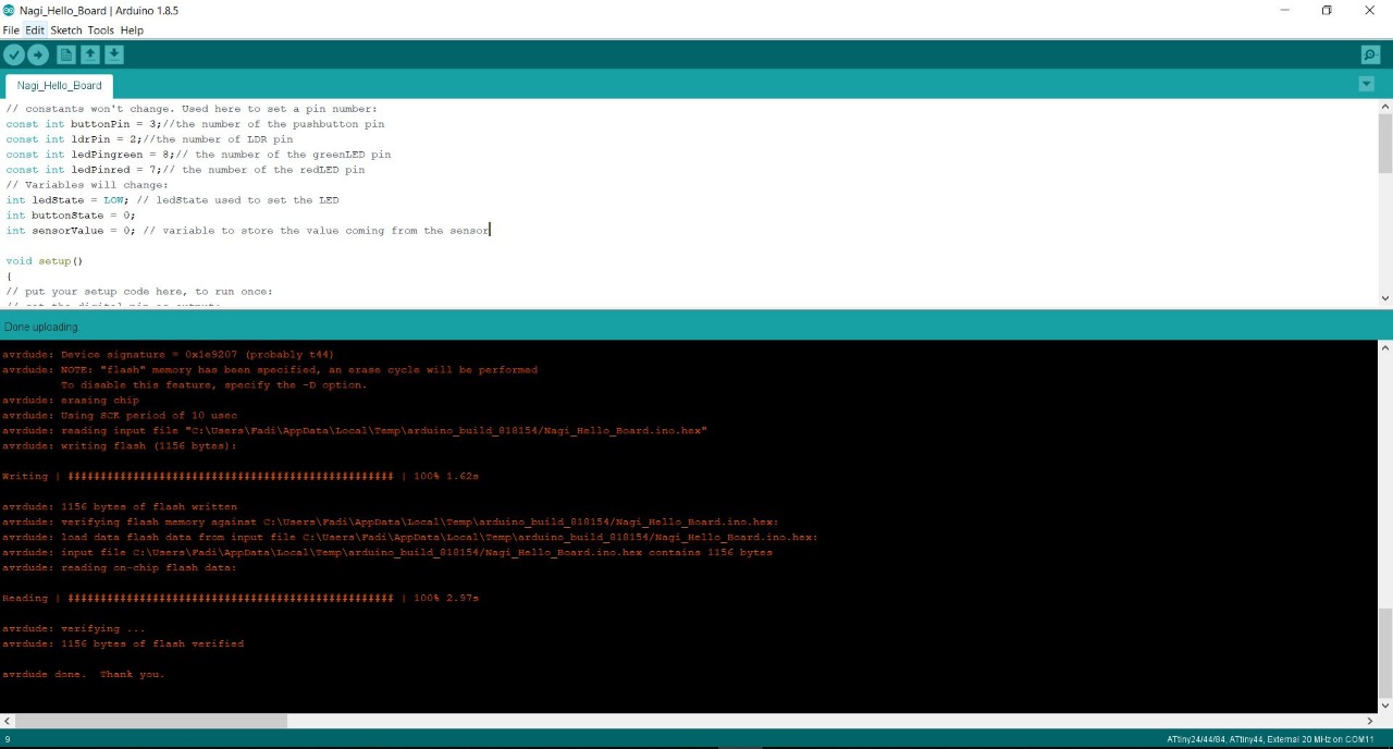
Upload
After writing the code I upload it by going to sketch => Upload Using Programmer and I test it...
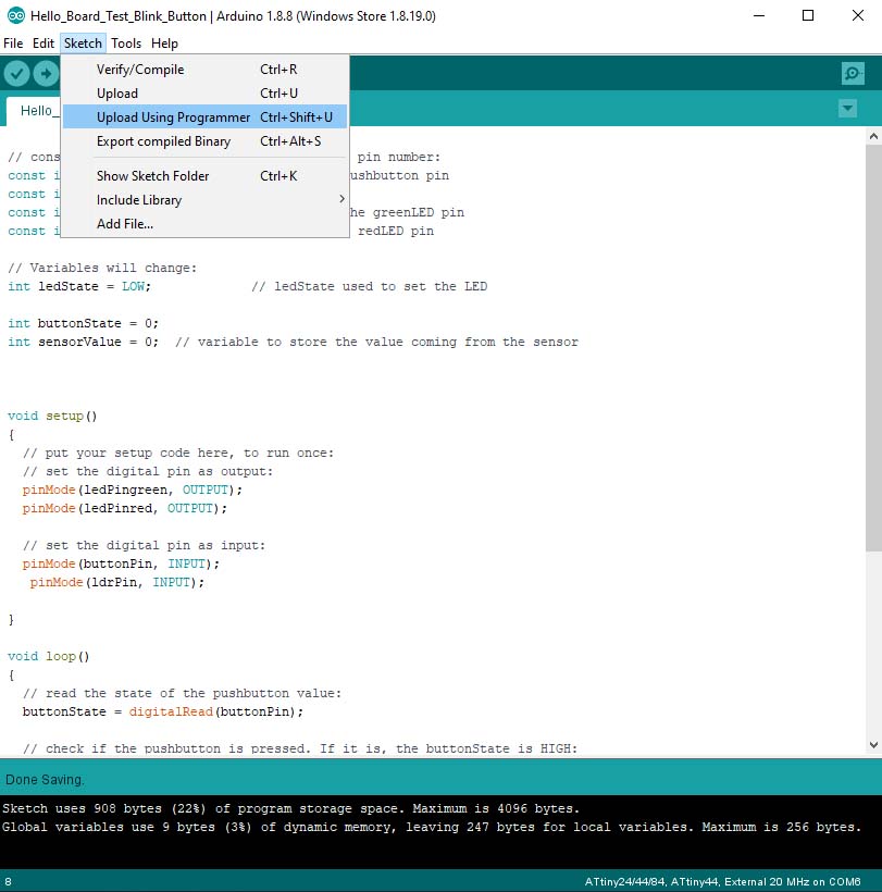
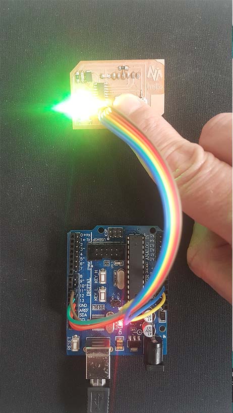
Testing Programm1
Programm 2
When I push the Button; If there is light than the Green led should turn on, if not the Red led should turn on .
                                // constants won't change. Used here to set a pin number:
                                const int buttonPin = 3;//the number of the pushbutton pin
                                const int ldrPin = A2;//the number of LDR pin
                                const int ledPingreen = 8;// the number of the greenLED pin
                                const int ledPinred = 7;// the number of the redLED pin

                                // Variables will change:
                                int ledState = LOW; // ledState used to set the LED

                                int buttonState = 0;
                                int sensorValue = 0; // variable to store the value coming from the sensor

                                int value = 0;

                                void setup()
                                {
                                // put your setup code here, to run once:
                                // set the digital pin as output:
                                pinMode(ledPingreen, OUTPUT);
                                pinMode(ledPinred, OUTPUT);

                                // set the digital pin as input:
                                pinMode(buttonPin, INPUT);
                                pinMode(ldrPin, INPUT);

                                }

                                void loop()
                                {
                                // read the state of the pushbutton value:
                                buttonState = digitalRead(buttonPin);

                                // check if the pushbutton is pressed. If it is, the buttonState is HIGH:
                                if (buttonState == HIGH)
                                {
                                // read the value from the sensor:
                                sensorValue = analogRead(ldrPin);
                                value = map(sensorValue,0,1023,0,100);
                                if ( value>50)
                                {
                                // put your main code here, to run repeatedly:
                                digitalWrite(ledPingreen, HIGH); // turn the LED on (HIGH is the voltage level)
                                digitalWrite(ledPinred, LOW); // turn the LED on (HIGH is the voltage level)
                                delay(1000);
                                }
                                else
                                {
                                // put your main code here, to run repeatedly:
                                digitalWrite(ledPingreen, LOW); // turn the LED on (HIGH is the voltage level)
                                digitalWrite(ledPinred, HIGH); // turn the LED on (HIGH is the voltage level)
                                delay(1000);
                                }
                                }
                                else
                                {
                                digitalWrite(ledPingreen, LOW); // turn the LED off by making the voltage LOW
                                digitalWrite(ledPinred, LOW); // turn the LED off by making the voltage LOW
                                }
                                // wait for a second

                                }
Testing Programm2
Programming using FabISP
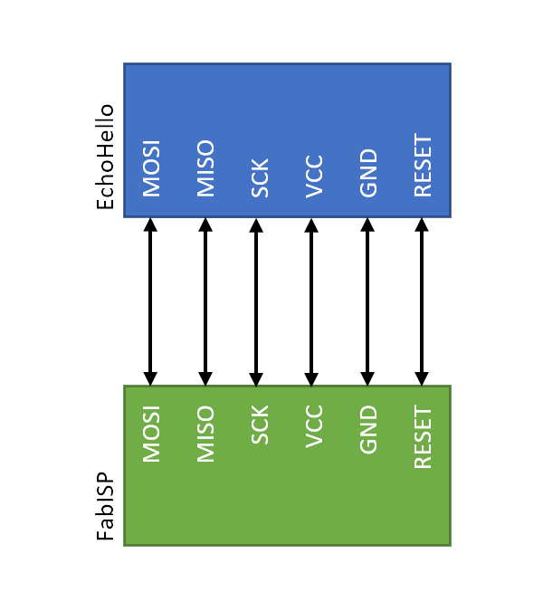
The connection
The connection between my FabISP and my Hello Board will be as follows: each Pin on a board is connected to it's similar on the other board.
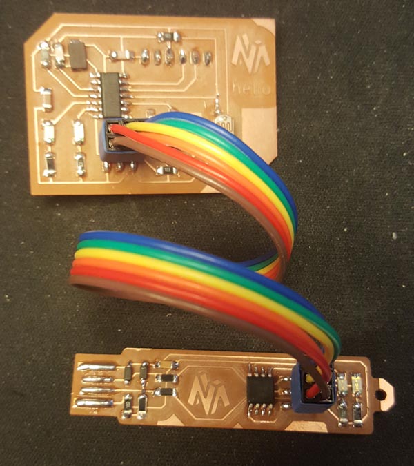
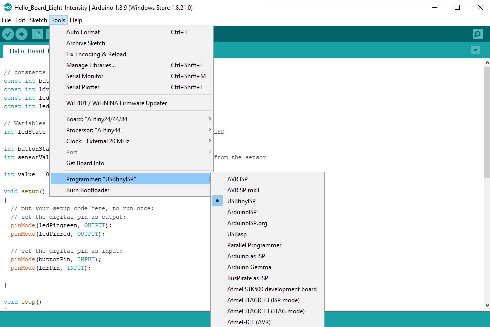
Now I will connect the FabISP to the computer, choose USBtinyISP as programmer and Upload using programmer
And that's it
And note that I had to connect my hello board to an FTDI cable in order to power it
Programming using C Language
Some needed information
To be able to program using C we have to understand the Registers.
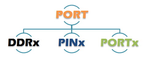
Each of the AVR Digital I/O Ports is associated with three (3) I/O register:
A Data Direction Register (DDRx), A Pin Register (PINx) and a Port Register (PORTx). Where x is the port A, B, C, etc.
Port
Port is a group of 8 pins, or set of pins used for exchanging data with the external world. In the ATtiny44 we have two ports A and B.
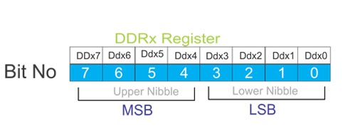
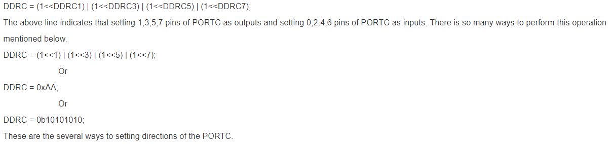
DDRx - Port X Data Direction Register

DDRx is an 8-bit register which configures data direction of the Port - Input / Output.
DDRx.n=0 > makes corresponding port pin as Input.
DDRx.n=1 > makes corresponding port pin as Output.
Note: Each physical pin of a port is configured independently and thus a port can have some of its pins configured as input an the others as output pins.
Examples:
- To make all pins of port A as input pins:
DDRA = 0b00000000; - To make all pins of port A as ouput pins:
DDRA = 0b11111111; - To make lower nibble of port b as ouput and higher nibble as input:
DDRB = 0b00001111;
Other way to write the code
PINx - Port X Input Pins Register

PINx is an 8-bit register used to read data from port pins, when port is configured as Input.
First set DDRx to zero, then use PINx to read the value.
If PINx is read, when port is configured as output, it will give you data that has been ouputted on port.
- Tristated input
- Pullup input
Examples:
- DDRA = 0b00000000; //set PA as input
- x = PINA; //read contents of PA
PORTx - Port X Data Register

PORTx is an 8-bit register which can be used for two purposes..
- For data output, when port is configured as output:
- Writing to PORTx.n will immediately(in same clock cycle) change state of the port pins according to given value.
- Do not forget to load DDRx with appropriate value for configuring port pins as ouput.
- to output 0xFF data on PB
DDRB = 0b11111111; //set all pins of port B as outputs
PORTB = 0xFF //write data on port - to output data in variable x on PA
DDRA = 0xFF; //set all pins of port A as outputs
PORTA = x; //output 8 bit variable on port - For configuring pin as tristate/pullup, when port is configured as input:
- When port is configured as input, then PORTx.n controls the internal pull-up resistor.
- PORTx.n=1 : Enables pullup for nth bit
- PORTx.n=0 : Disables pullup for nth bit, thus making it tristate.
- to make PA as input with pull-ups enabled and read data from PA
DDRA = 0x00; //make port A as input
PORTA = 0xFF //enable all pull-ups
y = PINA //read data from port A pins - to make PB as as tri stated input
DDRB = 0x00; //make port B as input
PORTA = 0x00; //disable pull-ups and make it tri state
Examples:
Examples:
For more information on AVR-I/O-Ports
For more information on Binary & Hexadecimal numbers
Writing the C code
Below is the C code that will alternate between the green led and the red led with a delay of 2 seconds when the button is pushed.
                            #include  #include  #define F_CPU 20000000UL //define frequency of the MCU // 0--> input
                                // 1--> output
                                //PA7 -->Red LED
                                //Pb2 -->Green LED
                                //PA2 -->LDR
                                //PA3 -->Button

                                int main(void){
                                DDRA = 0b10000000; //set pin PA7 as an output
                                DDRB = 0b0100; //set pin PB2 as an output

                                while(1){
                                if (PINA & 0b00001000) //check value of button at pin PA3
                                {
                                for (int i=0; i<1000; i++) //intiate loop { PORTA=0b00000000; PORTB=0b0100; // turn on Green LED _delay_ms(2000); PORTA=0b00001000; // turn on Red LED PORTB=0b0000; _delay_ms(2000); } } else { PORTA=0b00000000; PORTB=0b0000; } } }
The Code explanation.
DDRA = 0b10000000; //set pin PA7 as an outputThis sets the PA7 pin data direction to Output (red led).
DDRB = 0b0100; //set pin PB2 as an outputThis sets the PB2 pin data direction to Output (green led).
// PA2 as InputThis sets the PA2 pin data direction to Input.(Ldr)
while(1) {}This creates an infinite loop, as long as 1 is true.
if (PINA & 0b00001000) //check value of button at pin PA3This states the condition if the PINA bit-level is shifted to HIGH state.
for (int i=0; i<1000; i++) //intiate loop This creates a number of loop limited to 1000
PORTA = 0b00000000;
                         PORTB = 0b0100; // turn on Green LED
the Red LED is set off and the Green LED is set on.
_delay_ms(2000);it creates a delay of 2seconds
PORTA = 0b00001000; // turn on Red LED
                        PORTB = 0b0000;
the Red LED is set on and the Green LED is set off.
_delay_ms(2000);it creates a delay of 2seconds
else {if the first condition is not satisfied it will execute the below
PORTA = 0b00000000;
                         PORTB = 0b0000;
the Red LED is set off and the Green LED is set off.
To understand Makefiles click Here
To understand Fuses click Here
Group Assignment
In this group assignment we will try another architecture than the AVR.
ARM ARCHITECTURE
ARM, previously Advanced RISC Machine, originally Acorn RISC Machine, is a family of reduced instruction set computing (RISC) architectures for computer processors, configured for various environments.
ARM cores are used in a number of products, particularly PDAs and smartphones. Some computing examples are Microsoft's first generation Surface and Surface 2, Apple's iPads and Asus's Eee Pad Transformer tablet computers, and several Chromebook laptops.
Others include Apple's iPhone smartphone and iPod portable media player, Canon PowerShot digital cameras, Nintendo Switch hybrid and 3DS handheld game consoles, and TomTom turn-by-turn navigation systems.
ARM chips are also used in Raspberry Pi, BeagleBoard, BeagleBone, PandaBoard and other single-board computers, because they are very small, inexpensive and consume very little power.(-Source WIKIPEDIA-)
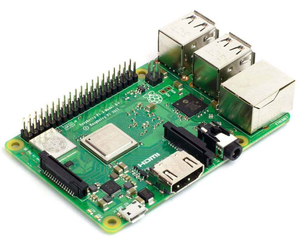
What is a Raspberry Pi?
The Raspberry Pi is a low cost, credit-card sized computer that plugs into a computer monitor or TV, and uses a standard keyboard and mouse. It is a capable little device that enables people of all ages to explore computing, and to learn how to program in languages like Scratch and Python. It’s capable of doing everything you’d expect a desktop computer to do, from browsing the internet and playing high-definition video, to making spreadsheets, word-processing, and playing games.
What is the difference between programming the Arduino and the Raspberry Pi?
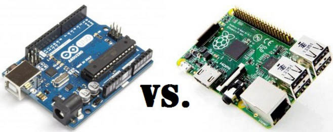
The Arduino is programmed using either Arduino code or C/C++. The Arduino code is the easyiest way to program because it can be uploaded using Arduino Ide and the pins are defined by simple numbers and it has a library with a lot of examples as for the C-code it is more complicated it should be uploaded using a terminal and each pin is defined by using hex and binary numbers depending on the Port location.The advantage of the c-code is that it takes less memory on the microcontroller.
The Raspberry Pi is a general-purpose computer, usually with a Linux operating system, and the ability to run multiple programs. It is more complicated to use than an Arduino. It can be programmed using a variety of languages and Python is one of the primary programming languages hosted on the Raspberry.
The advantages of Python is that you can run the code directly through the Raspberry and see the results. Some of it's features are : It is excellent for beginners and superb for expert , suitable for large projects and as well as small ones , embeddable , simple , stable and it has a powerful standard library(pre-built code, sub-routines ...)
Check This Tutorial to start learnning Python coding
Files
Click Here to download program 1 File
Click Here to download program 2 File