First sketches
AUTOMATED INDOOR HANGING GARDEN
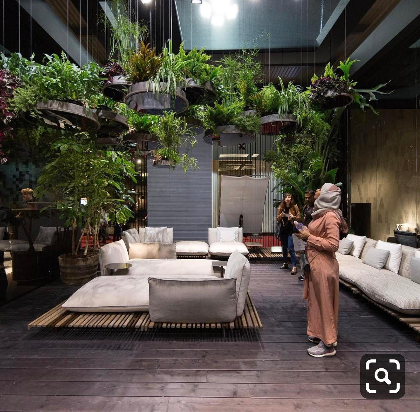
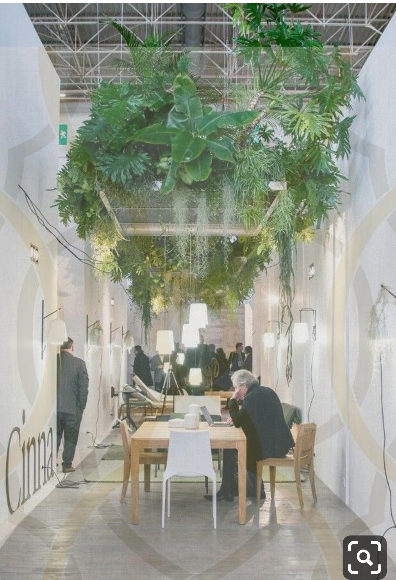
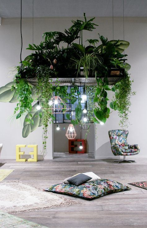
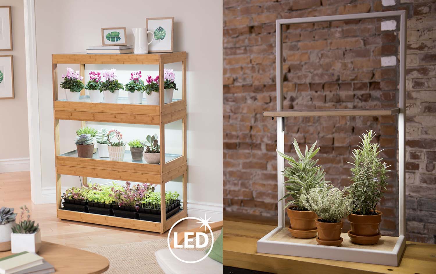
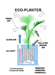
Inspiration photos
The Automation in my project will take care of the following:
- Lighting
- Watering
- Ventilation
The system (Concept & Research)
Check W13 Applications and Implications for more details about the IDEA and RESEARCH.
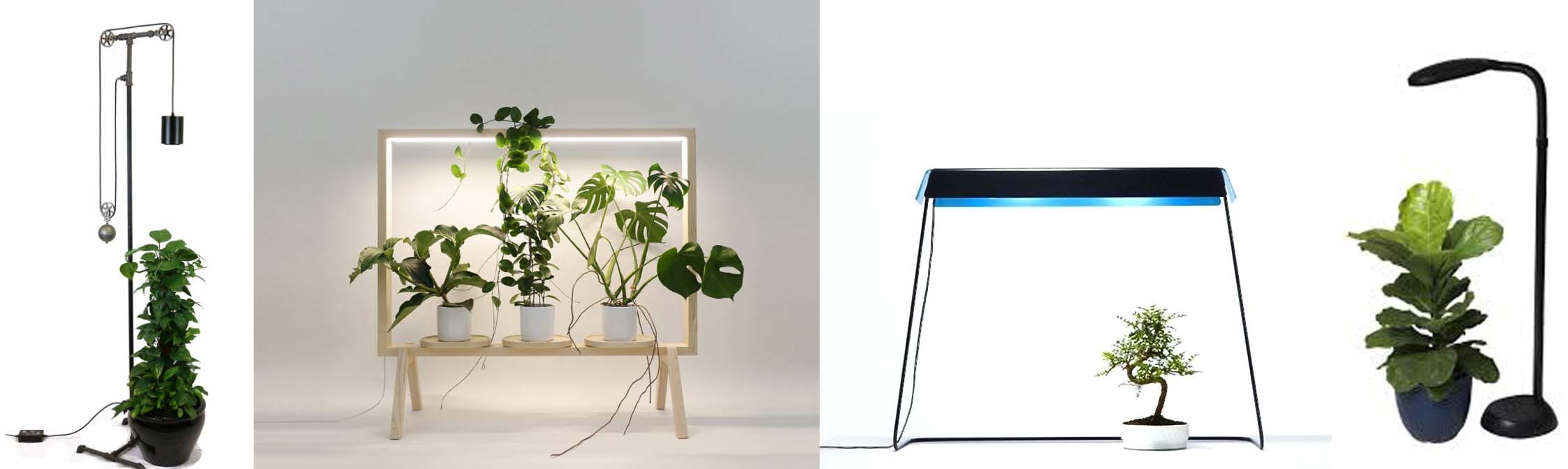
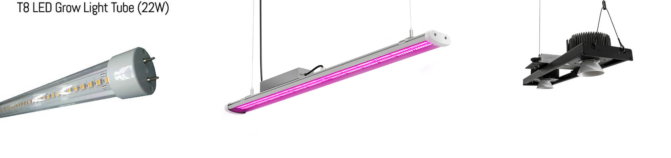
Lighting:
Every plant needs an optimal quantity of light during daytime for a good growth.
A grow light will be installed and controlled via a clock and a light sensor.
Examples:
Watering:
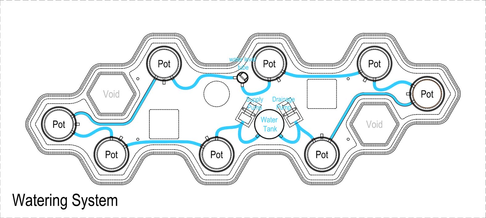
The watering system will be from the bottom up by soaking the plant pot in water for a certain time until the top of the potting mix is wet. This technique will save water because all the unused water will return to the main water tank where we can also add the required nutrients.
Two controlled water pumps and a moisture sensor will do the job by supplying and draining the water when needed.
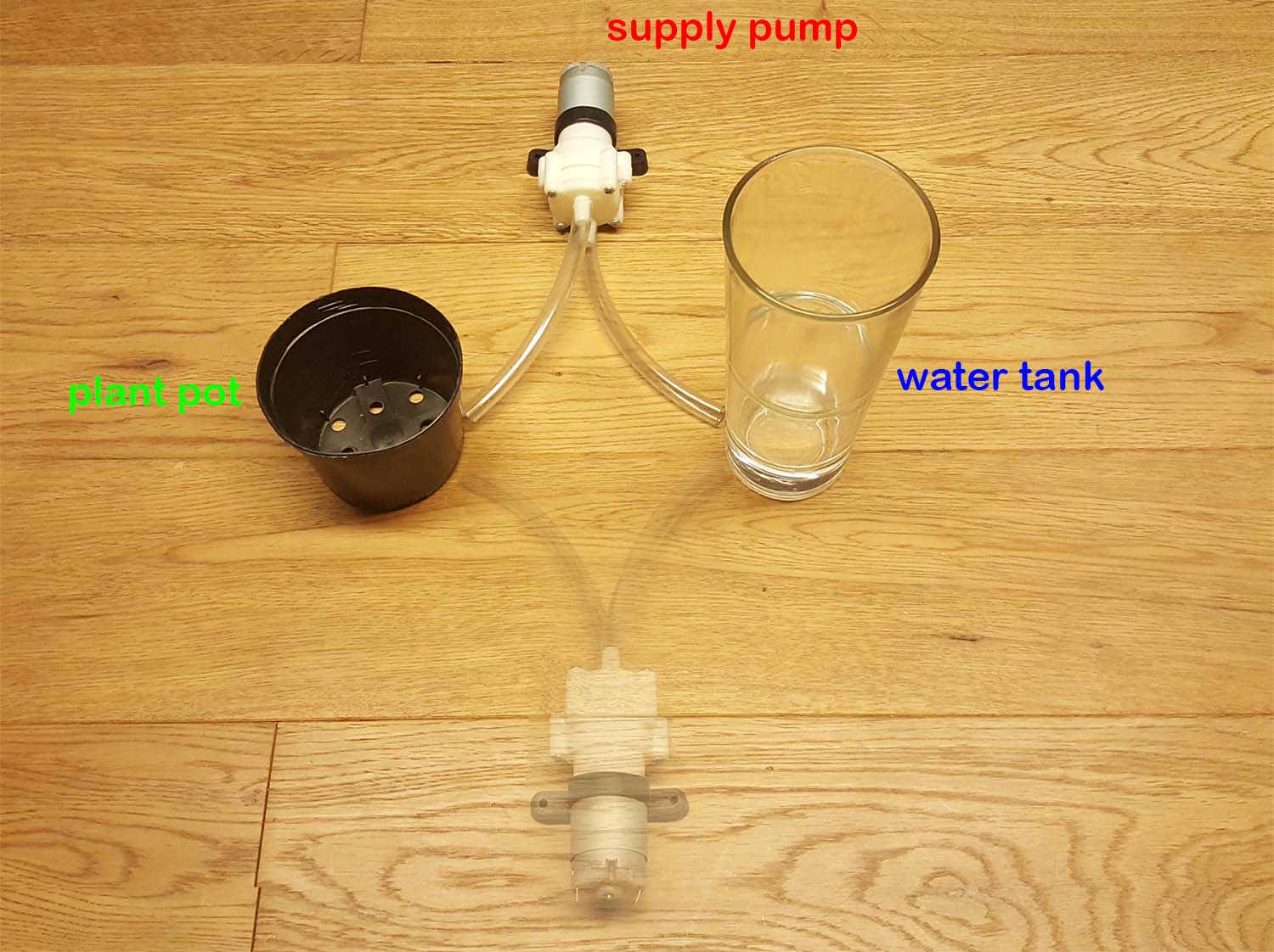
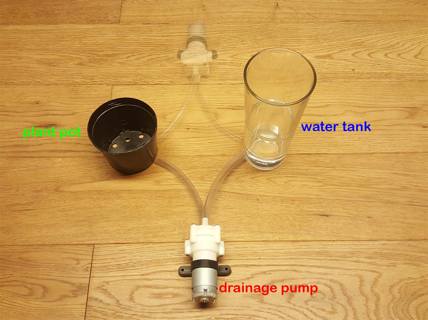
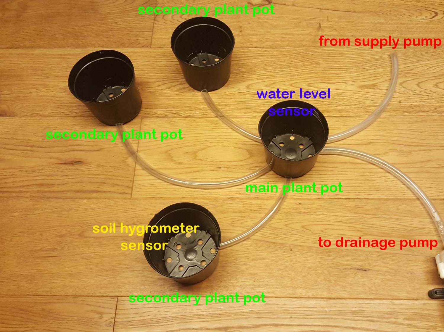
A water level sensor will be put on the main plant pot to detect and control the water level on all the secondary connected pots; All the pots are on the same level and will be linked by gravity.A soil moister sensor will be installed on one of the secondary pots (supposing that all the plants have the same water needs).
Ventilation:
Ventilation is important for indoor garden, because it allows for the removal of excessive heat and humidity, and helps provide fresh air.
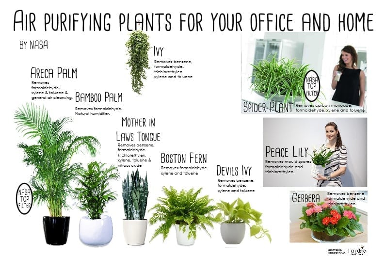
Below are some Air purifying plants:
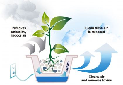
A controlled fan will do the job by sucking air from the plant soil surface through the potting mix and roots, allowing by that the removal of excess moisture and air purification (the plant roots will act as a filter and remove toxins).
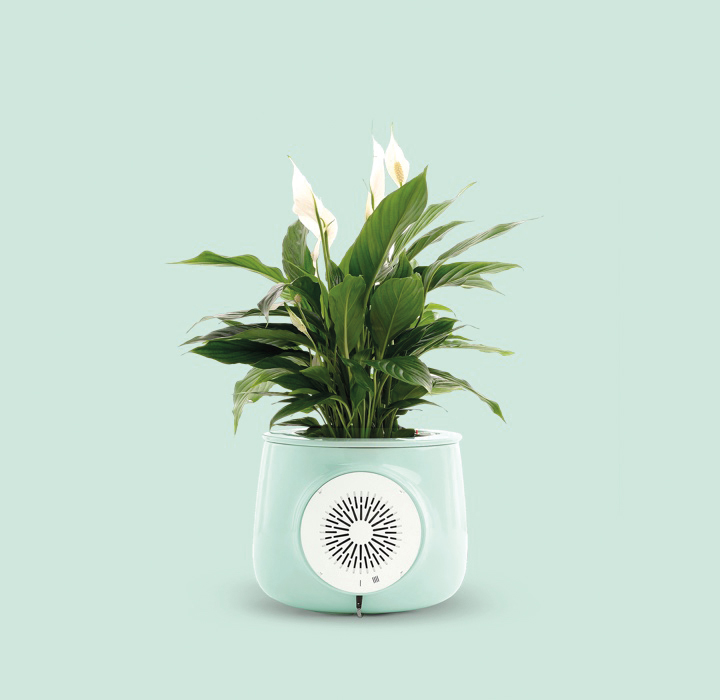
CLAIRY Product is an example of a natural air purifier

Plant Air Purifier is another example of natural air purifier
The Project Planning
Project phases
The project will be divided into the following phases:
- The Design
- The Production
- The Programing
- The Assembly
- The final Result
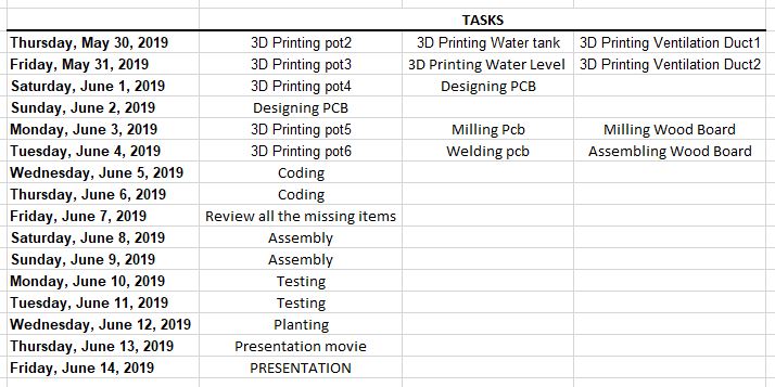
Time management
In order to finish the project and present on the 14th of June 2019 the below dates and tasks should be followed and achieved:
The skills used
In order to finish my final project, several skills learned during the last 19 Weeks in FabAcademy have been used:
- 2D/3D design
- Laser cutting
- 3D Printing
- CNC Milling
- Electronic Design
- Electronic Production
- Programing
- Network and communication
1-The Design
My project will be consisting of different parts that should be designed and linked together:
- The Supporting Structure or The Tray.
- The Lighting Support.
- The Planting Pots.
- The Watering System (Water tank and tubing).
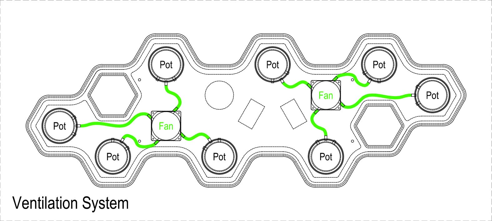
- The Ventilation System (Fan and ducting).
- The Automation System (microcontroller and sensors).
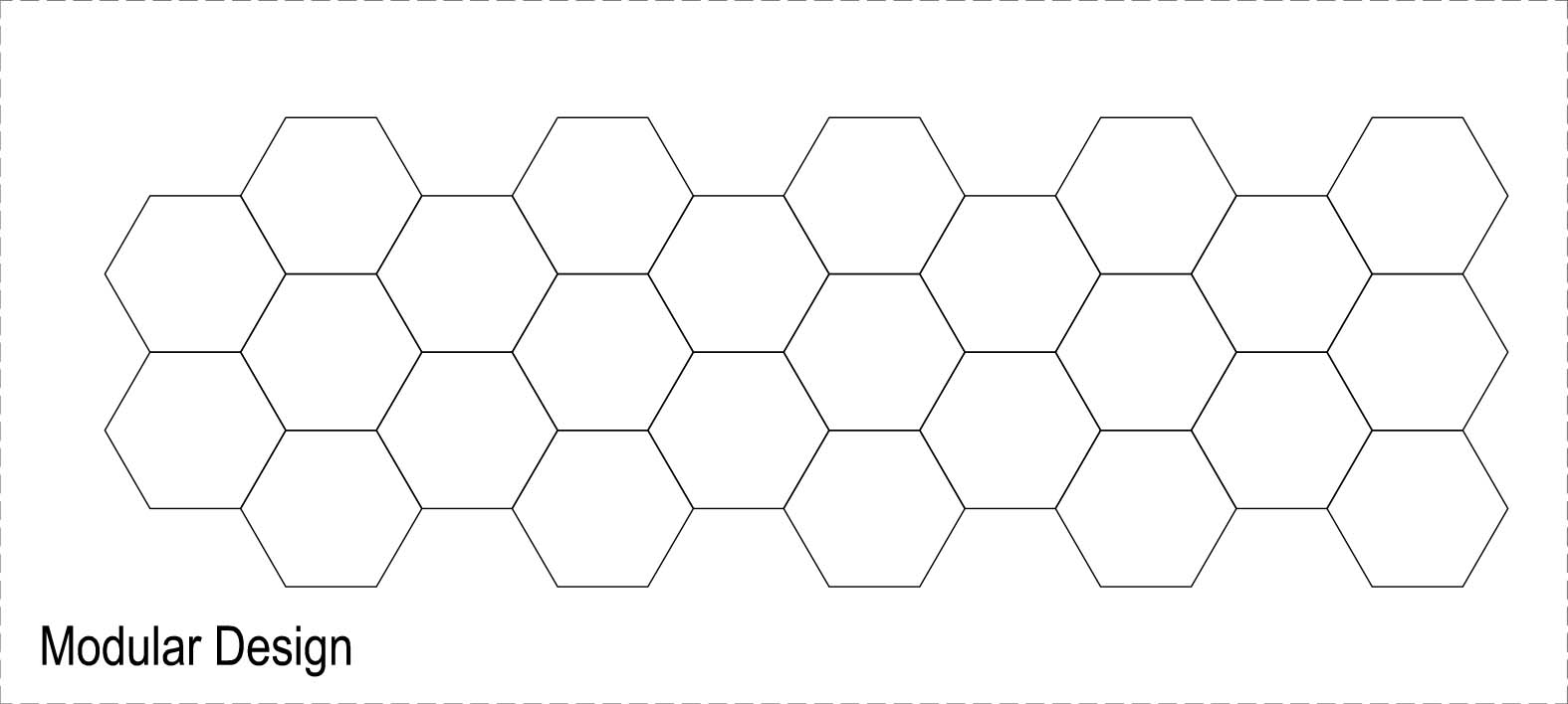
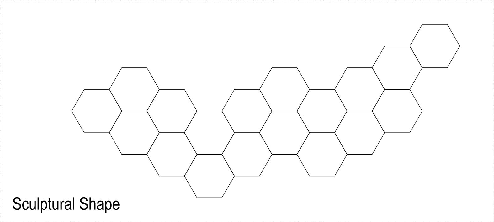
1.1-The Tray
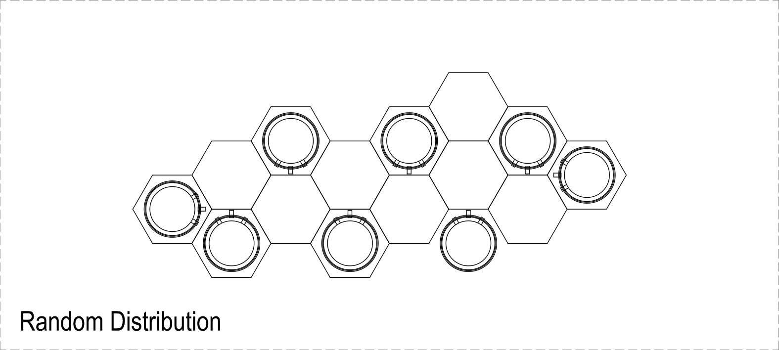
The Tray will be conceived in a Modular Design so it can be fabricated in any size we want based on the space it will be installed in.
This Modular design in Hexagonal form will make it also possible to have it in any Sculptural Shape we want.
The Planting Pots can have a Random Distribution on the Tray and the remaining places will be used for the other Functions: like the Water Tank, the fans, the Controller and even a Void to have a better visibility of the plants through the plate.
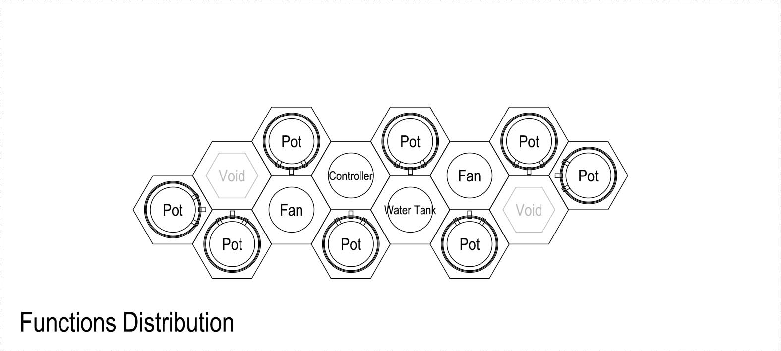
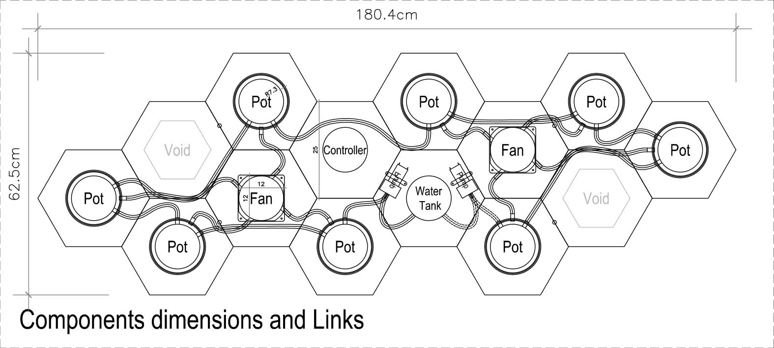
The Modular Hexagon form is resized to be able to fit all the needed Components with their respective links.
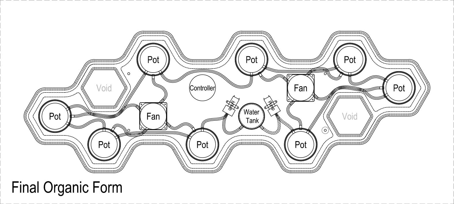
And than the Tray boundary is adjusted to take its final Final Organic Form
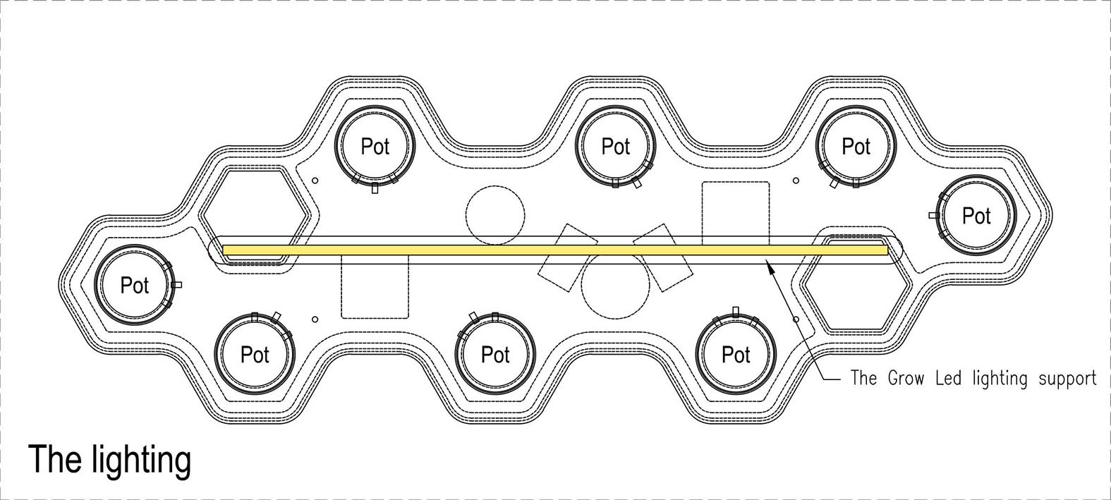
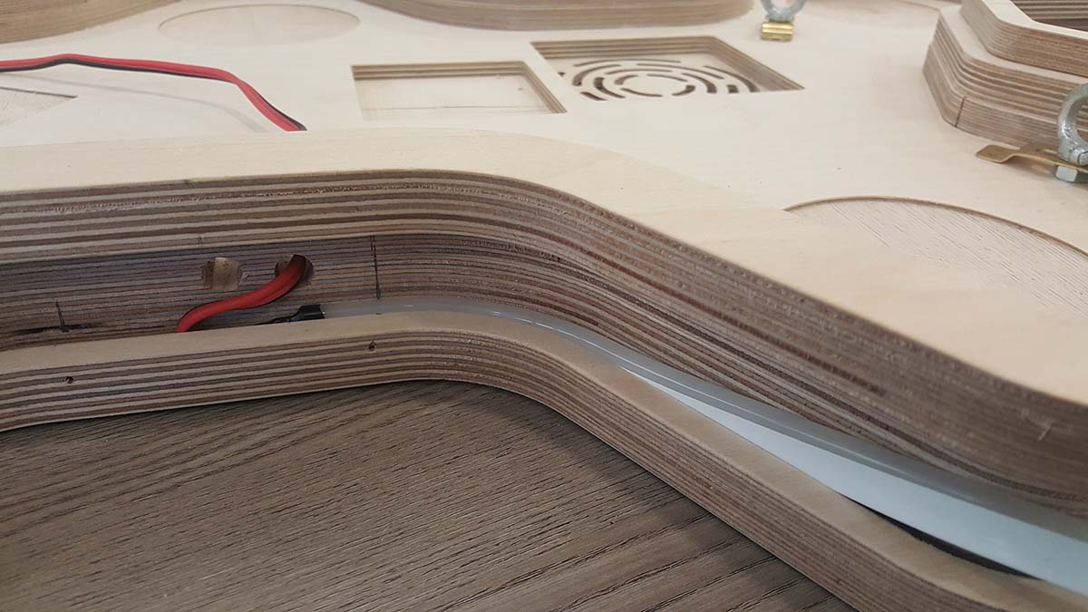
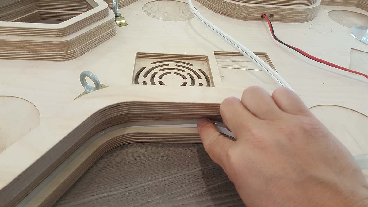
1.2-The Lighting Support
The Grow led Light strip will be integrated in a slim profile placed above the tray and supported by the same cables holding the tray.
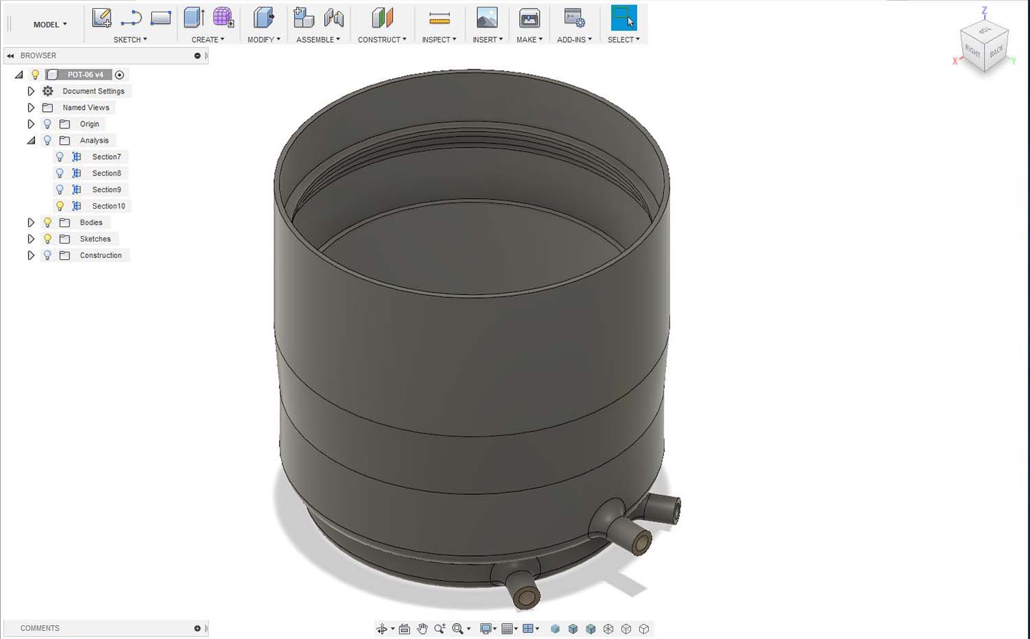
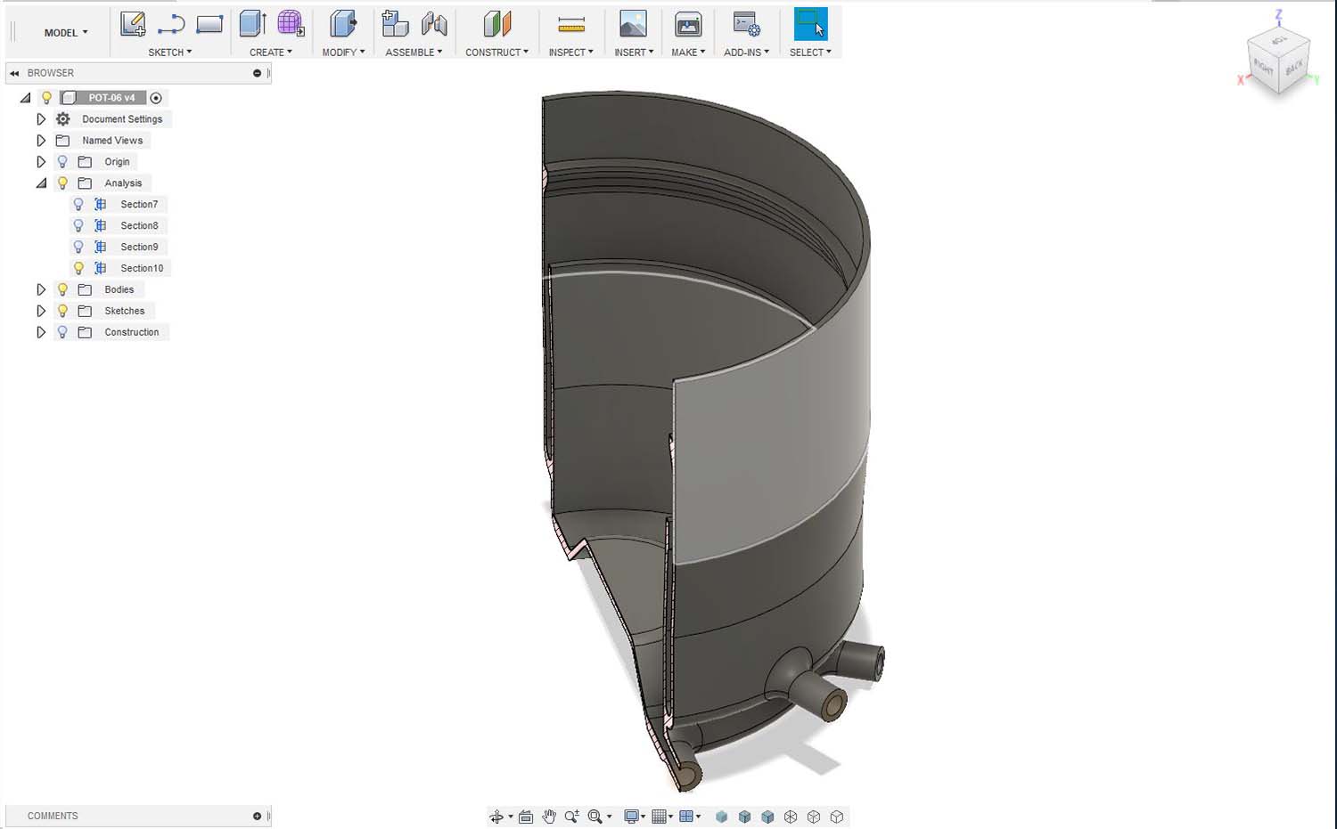
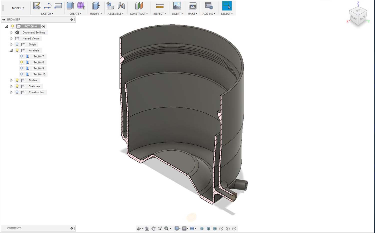
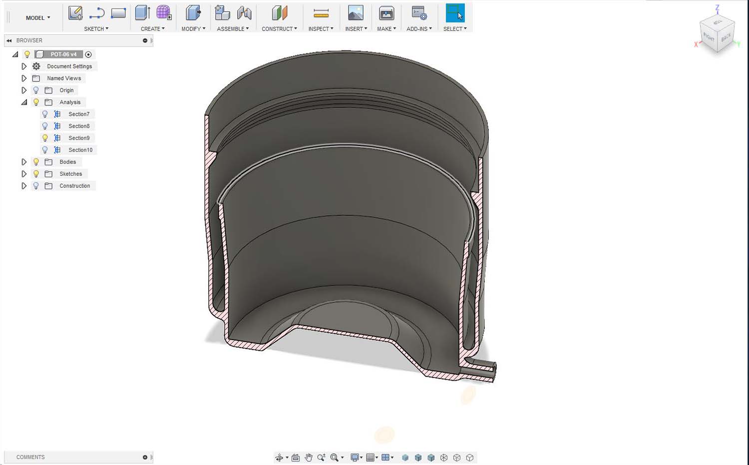
1.3-The Planting Pots
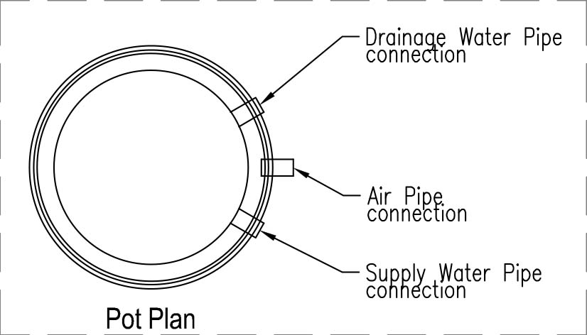
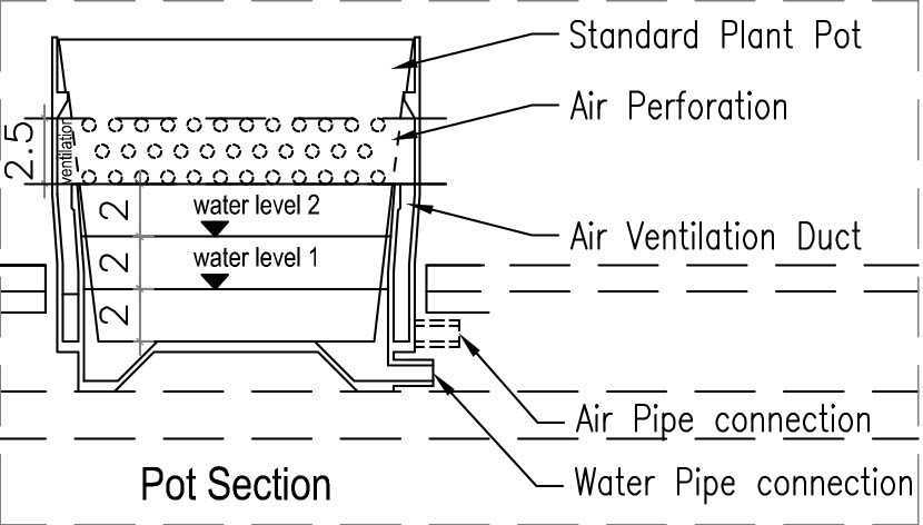
The Planting Pot is designed to incorporate a standard pot and have one water supply pipe connection , one drainage pipe connection and a ventilation pipe connection. The standard pot should be perforated as shown in the below section to allow the ventilation from the upper layer.
1.4-The Watering System (Water tank and tubing)
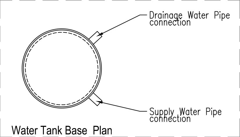
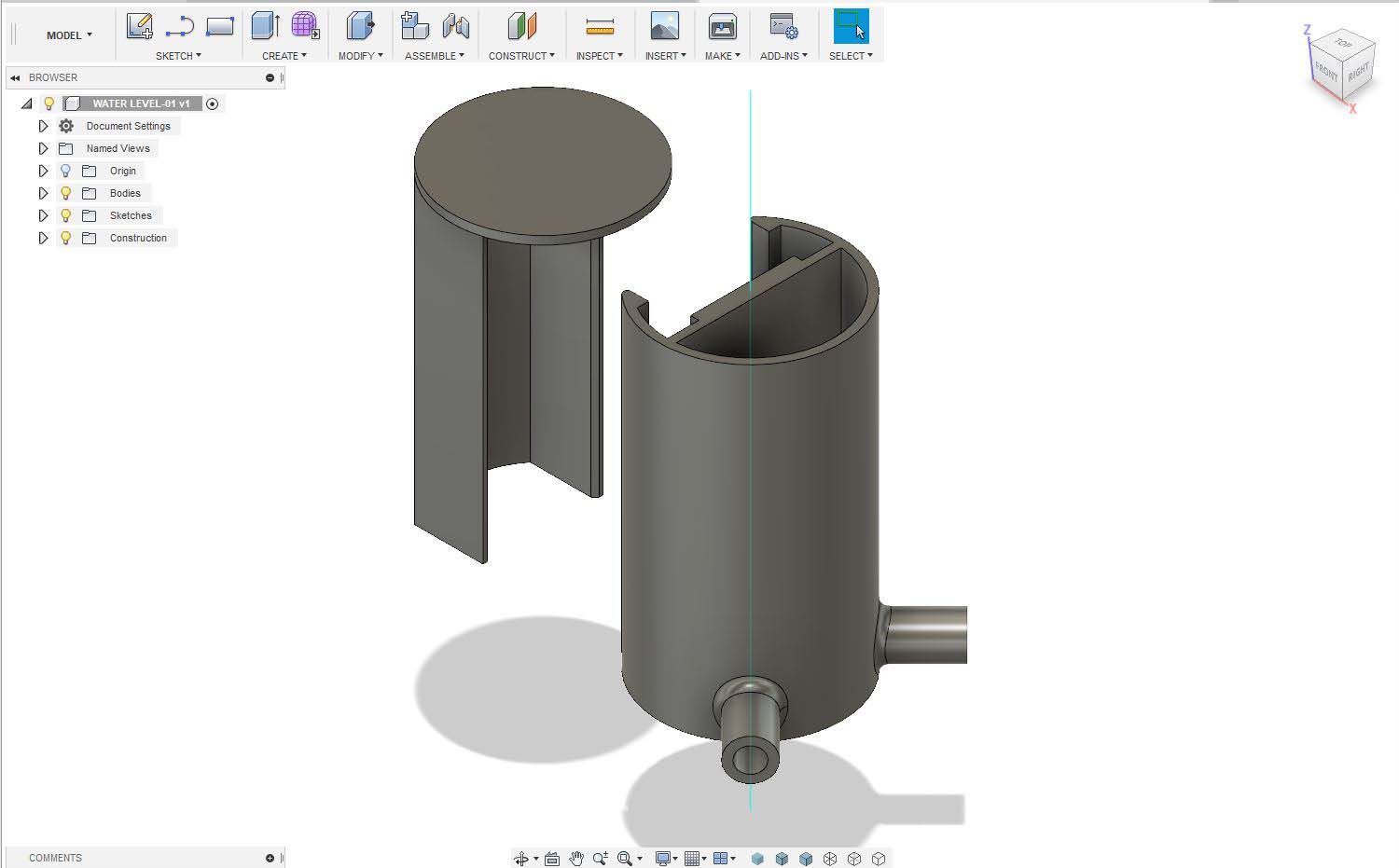
I will use a transparent container as a water tank , and it will be sealed to a 3D printed base that have one connection to the water supply pump and a connection to a water drainage pump.
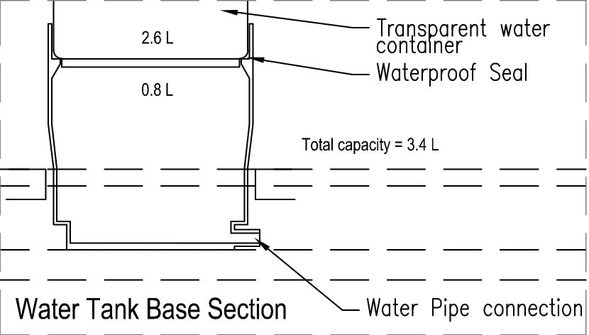
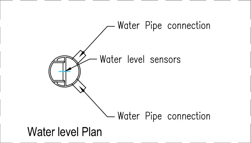
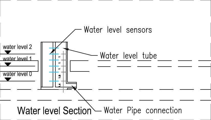
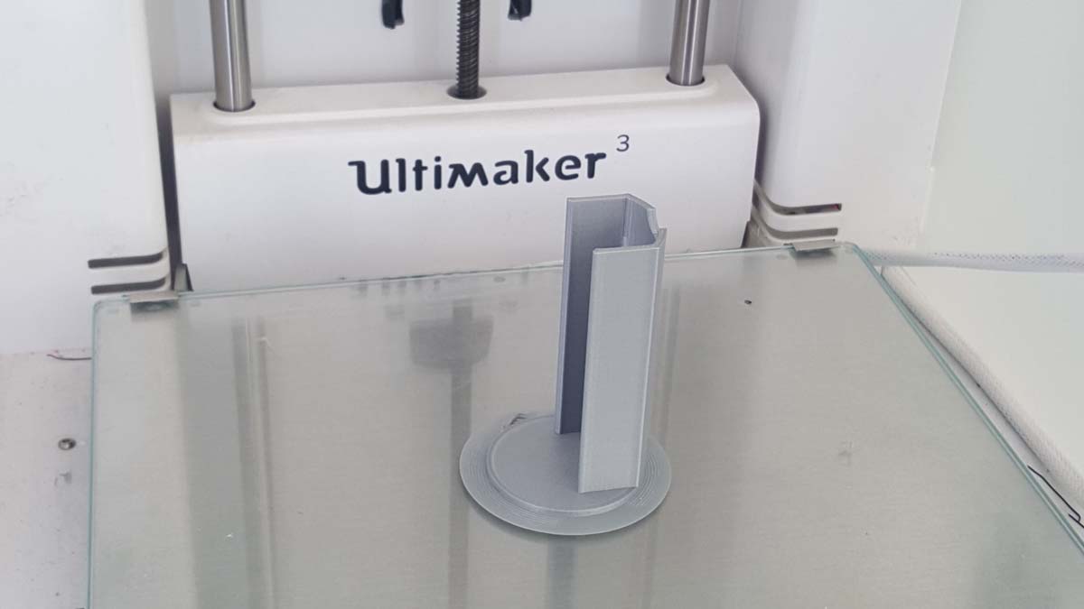
The water supply pump is connected to one pot connection and the second is connected to another pot . The last pot connection pipe is connected back to the drainage pump as shown in the below. And in the circuit I have installed a water level detection tube that will be detecting the water level via sensors in all the pots simultaneously (by gravity) at each running cycle.
Below is the water level detection tube plan and section.
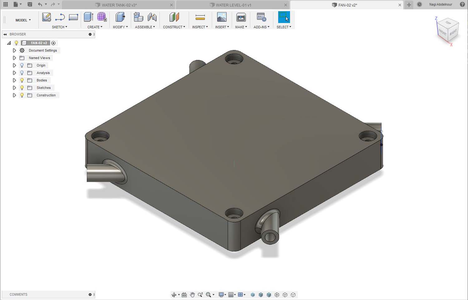
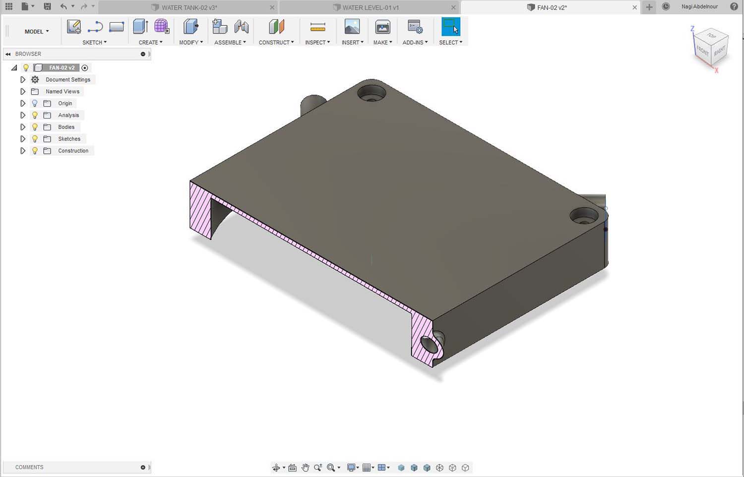
1.5-The Ventilation System (Fan and ducting).
The ventilation Duct is designed to be connected to a standard 12V / 12x12cm Fan , it has four pipe connection to be linked to the Planting Pot.
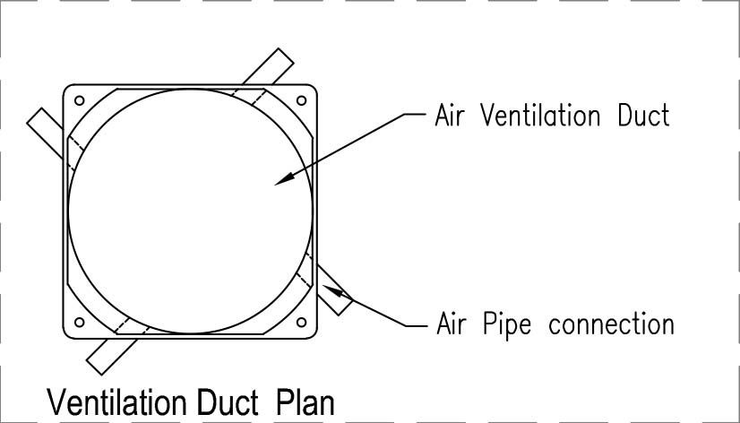
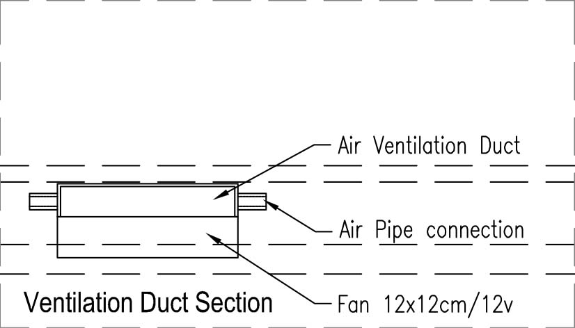
The air is sucked through the top layer soil and the bottom pot holes allowing the filtration through the soil and the roots and going out from the bottom of the Tray.
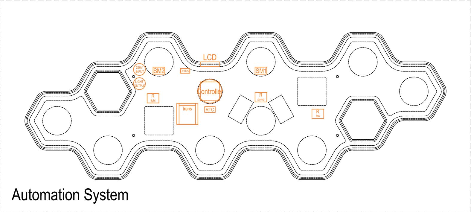
1.6-The Automation System (microcontroller and sensors)
The microcontroller will be place in a central area. The input/ouput devices and relays will be placed around it as below.
The PCB Board will be designed according to these places in order to have a minimum and clean wiring.
2-The Production
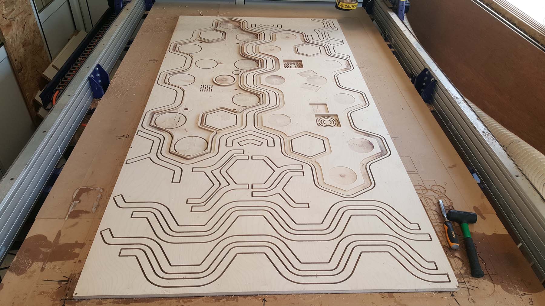
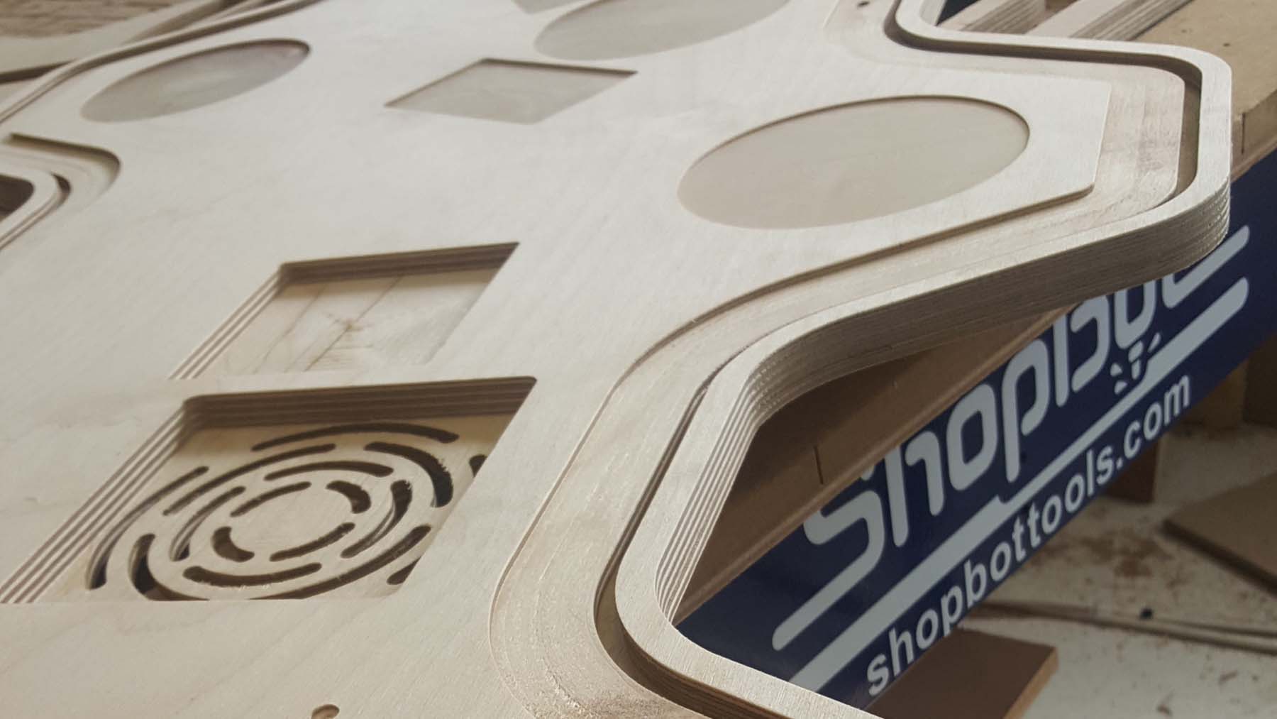
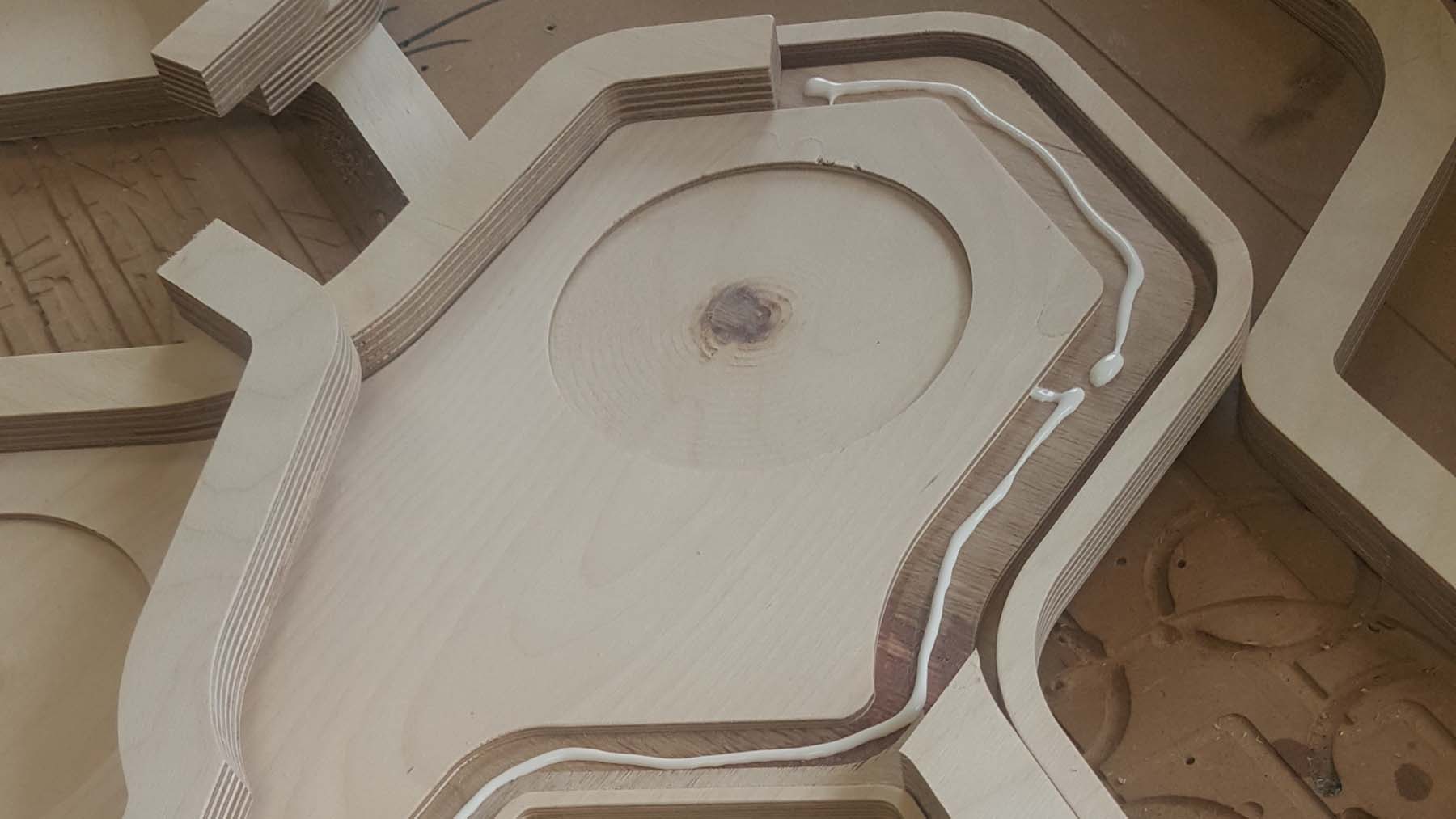
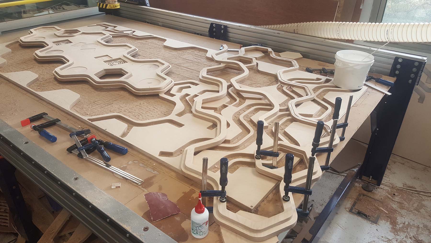
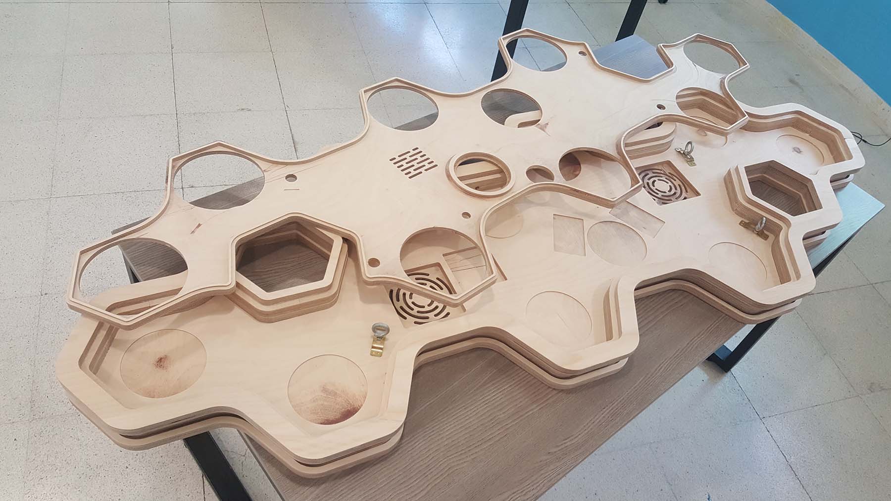
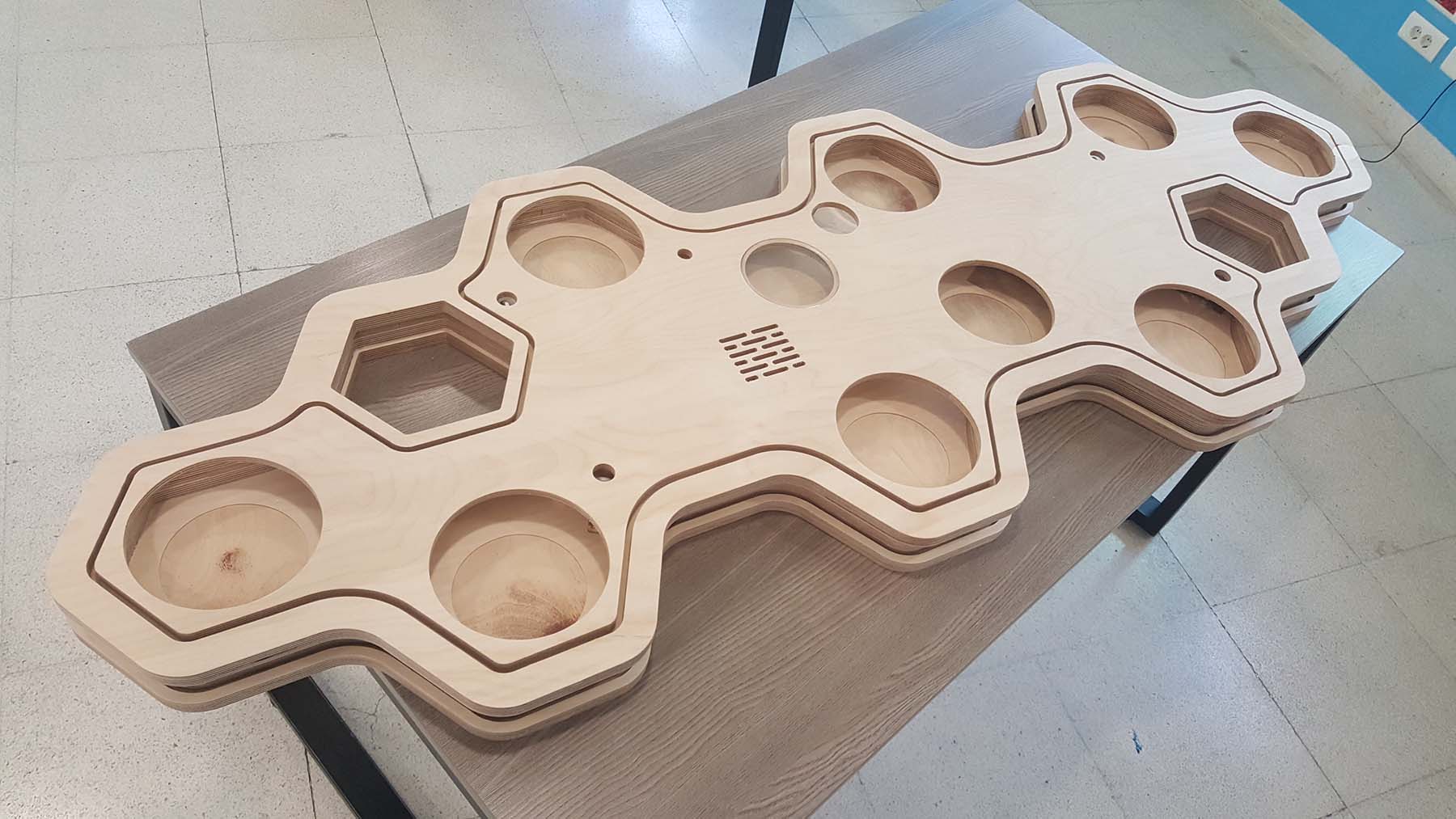
2.1-The Tray
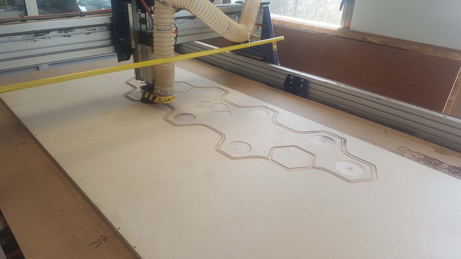
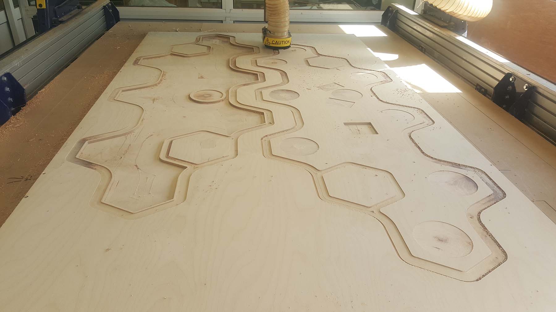
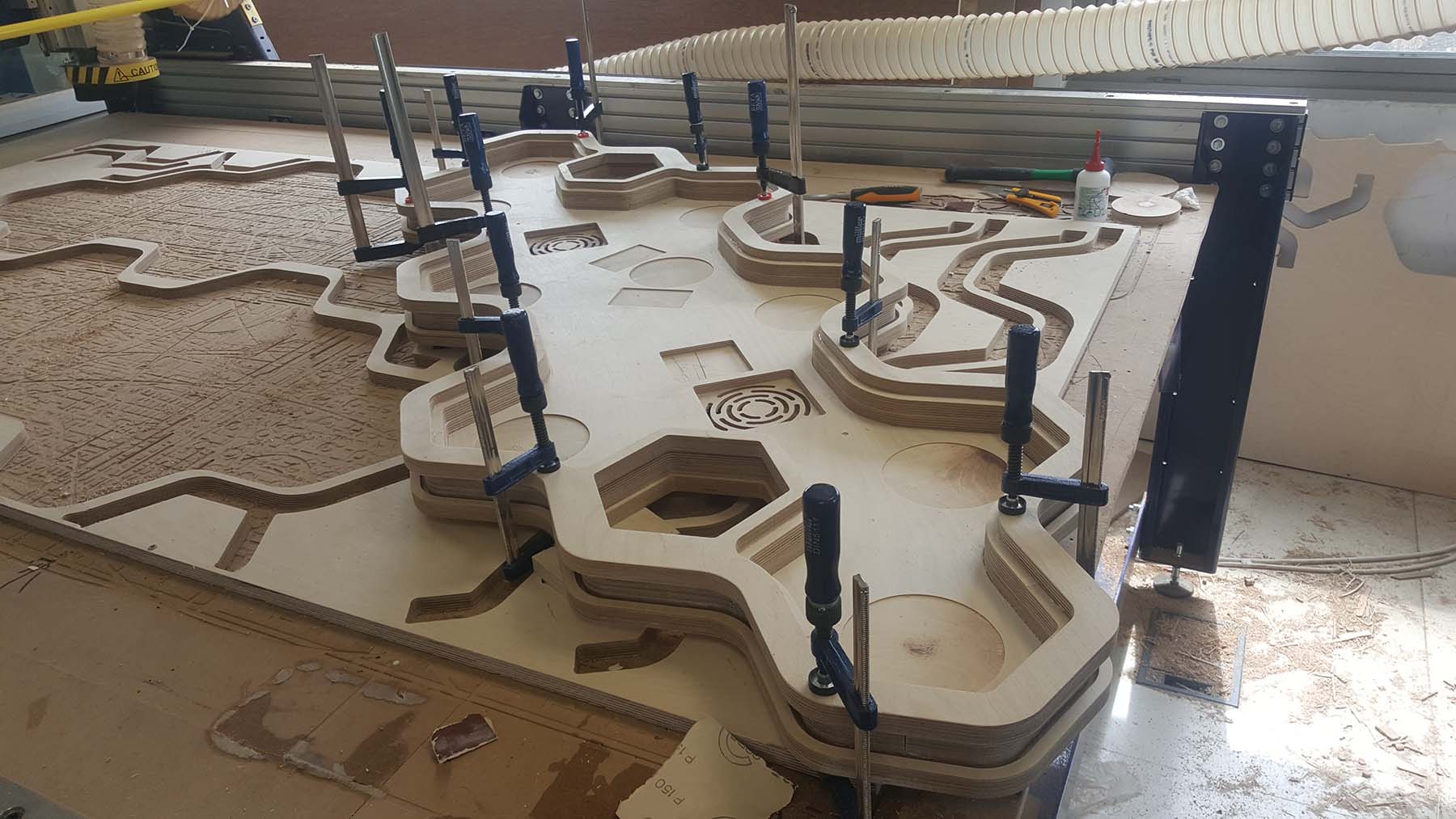
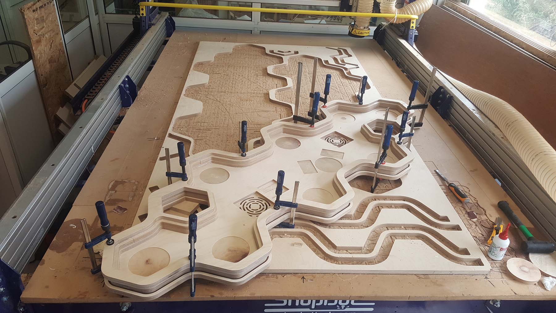
CNC machine will be used for the fabrication of the wooden tray.
Refer to W8 Computer Controlled Machine for more details about the process.
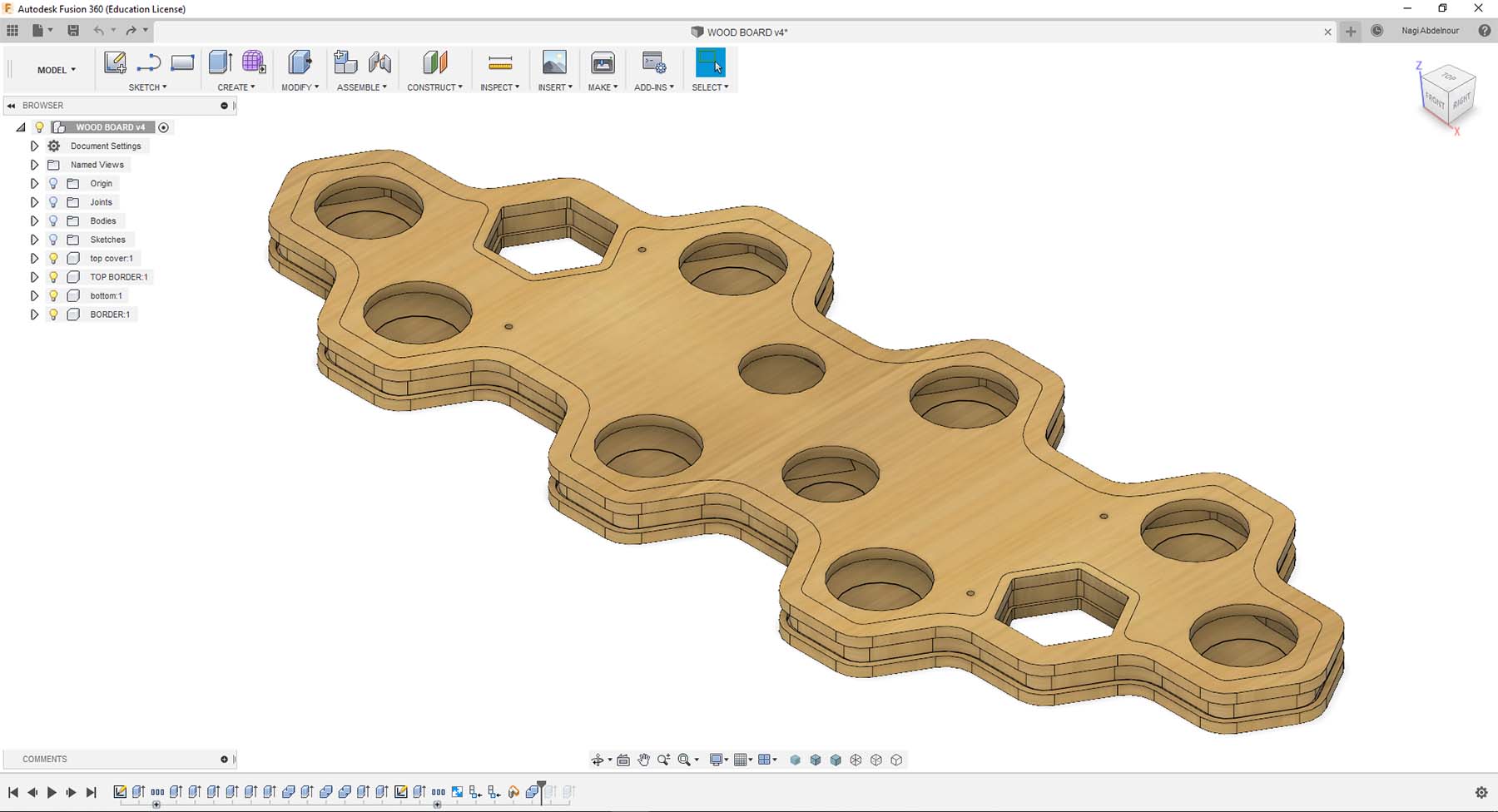
Below is the fusion model
Below is the dxf cutting file.
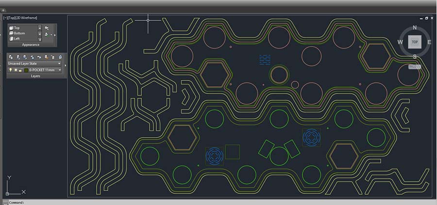
Click Here to download the dxf file.
And here are the production photos
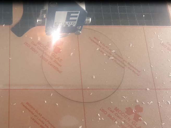
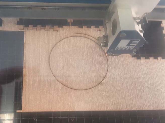
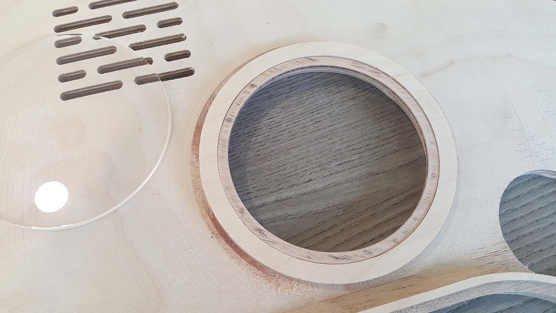
Now I will use the laser cutter to produce the plexi cover for the pcb board and the wooden ring that holds it.
Refer to W4 Computer Controlled Cutting for more details about the process.
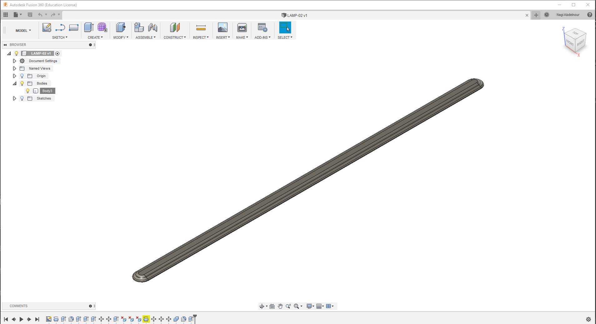
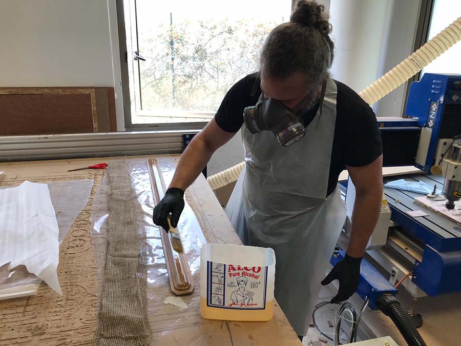
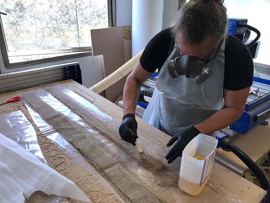
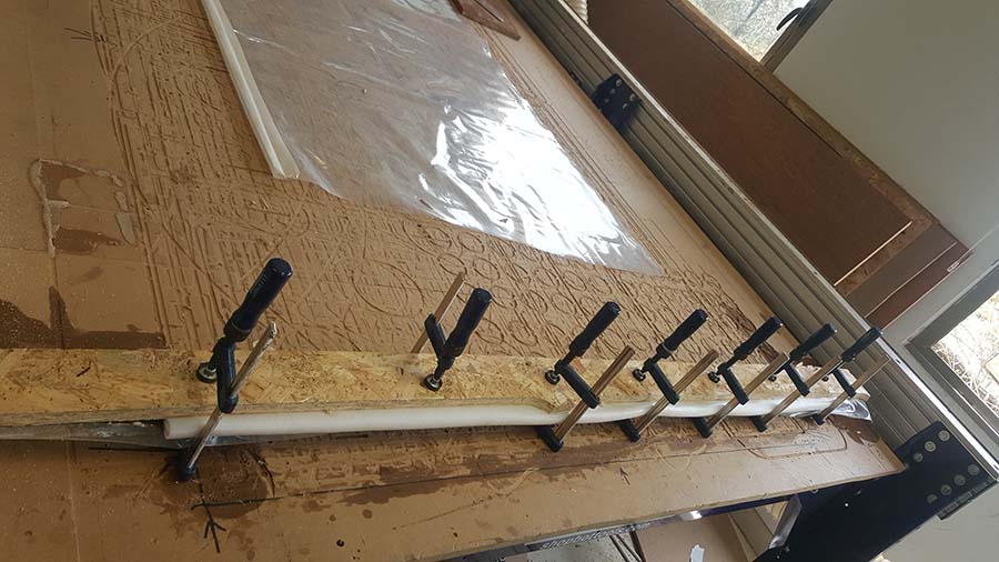
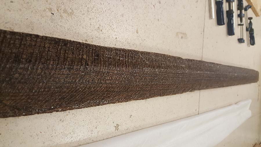
2.2-The Lighting Support
Composite material will be used for the fabrication of the lighting support.
Refer to W18 Wild Card for more details about the process.
Below is the fusion model
Click Here to download the STL file.
Below is the g-code generation process.
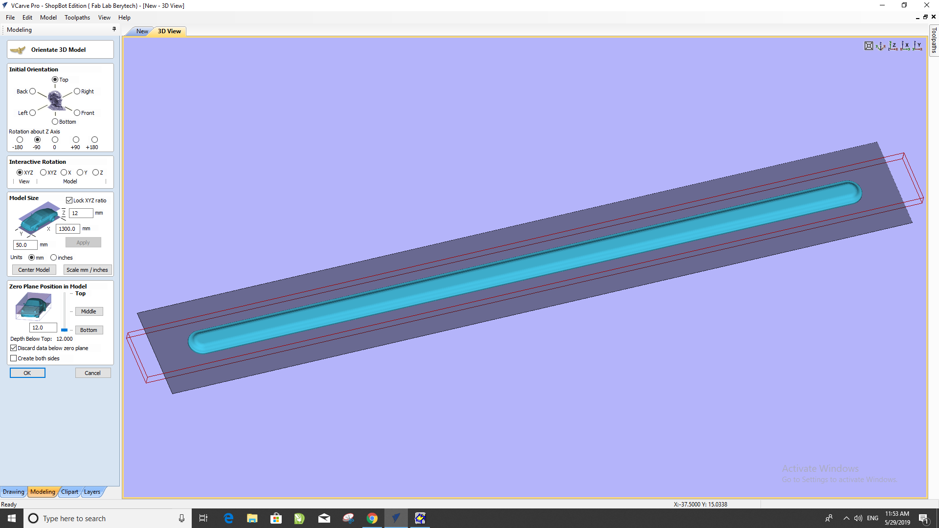
Click Here to download the g-code files.
And here are the production photos
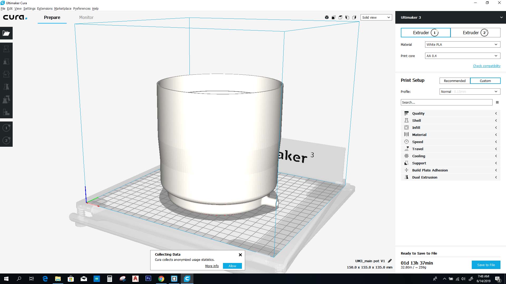
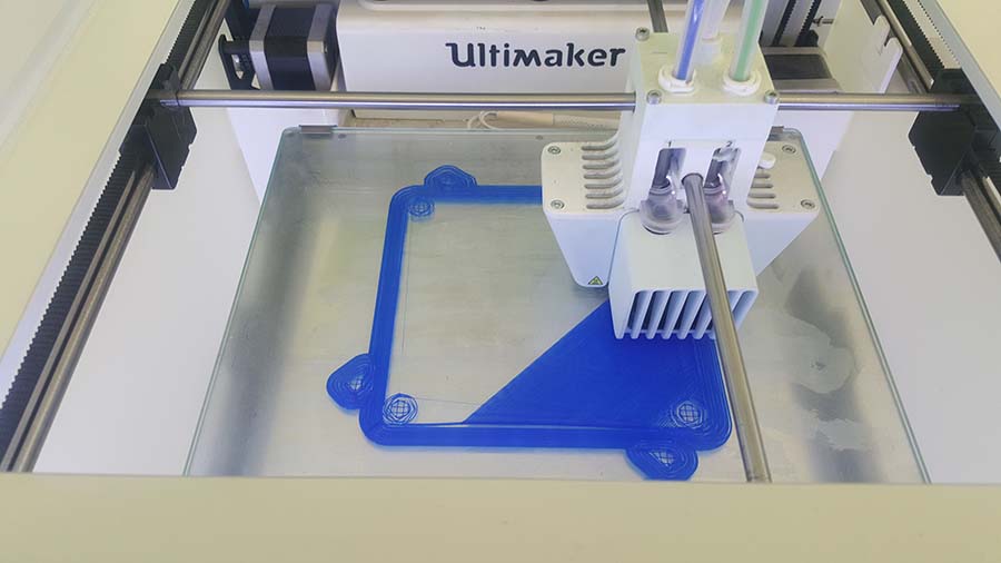
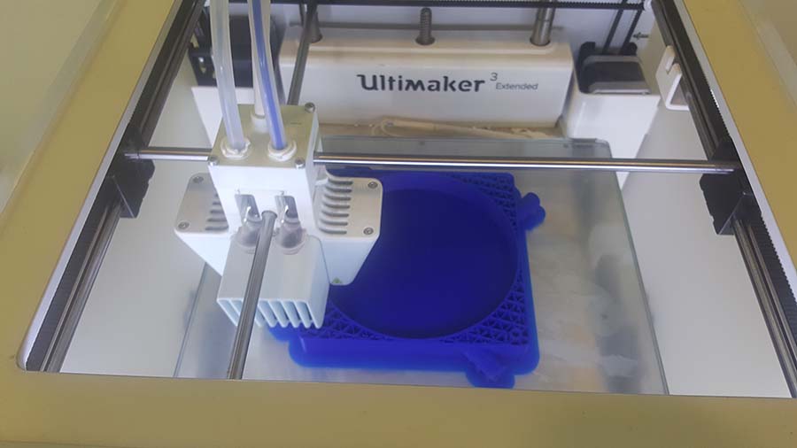
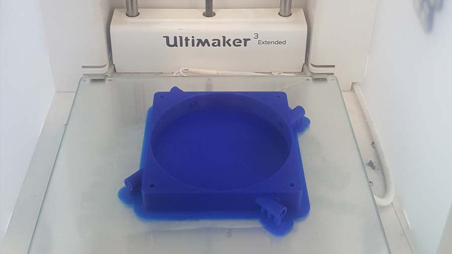
2.3-The Planting Pots
The planting pots will be 3D printed.
Refer to W6 3D Scanning and Printing for more details about the process.
Below is the fusion model
Below is the g-code generation process.
Click Here to download the STL file.
Click Here to download the g-code file.
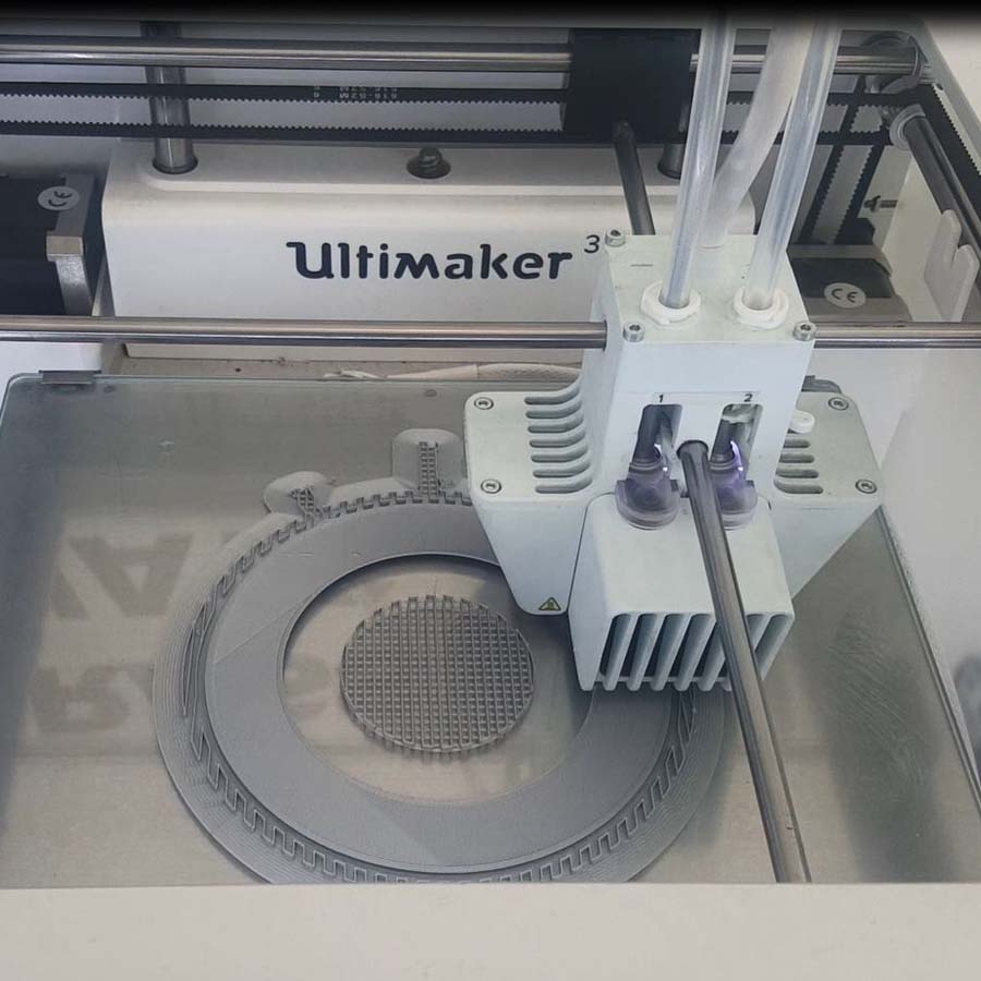
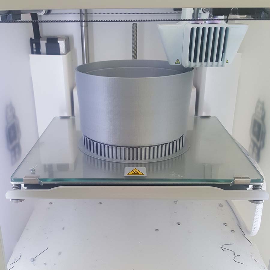
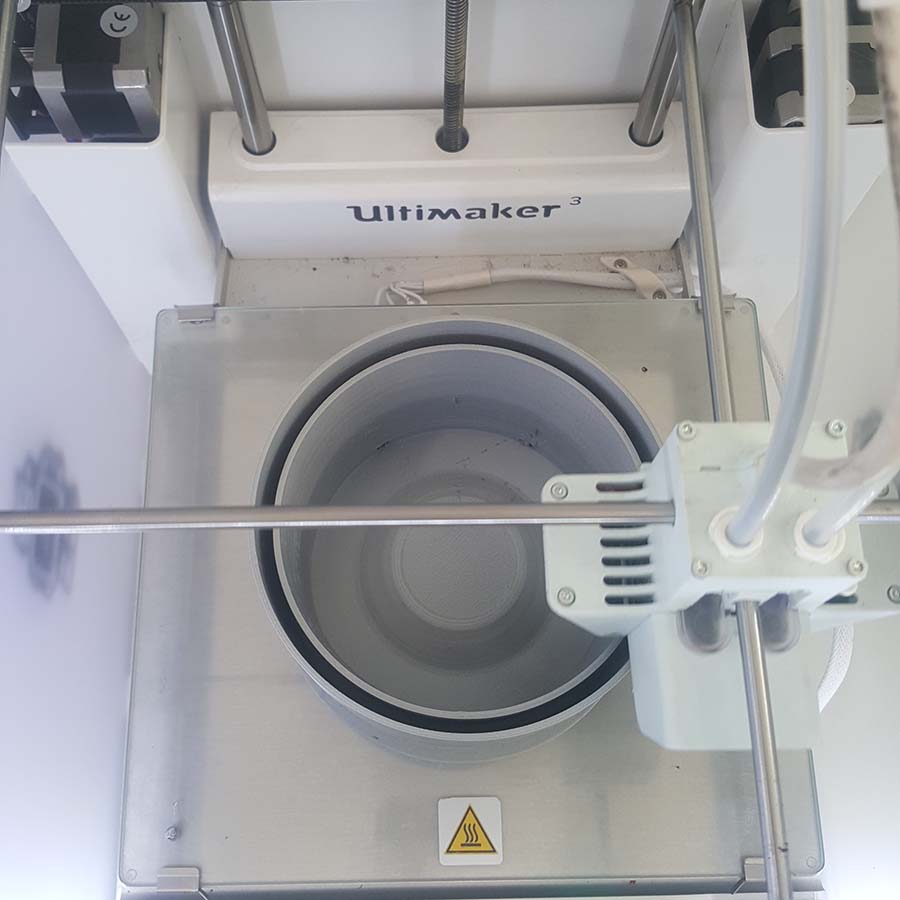
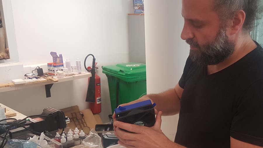
And here are the production photos
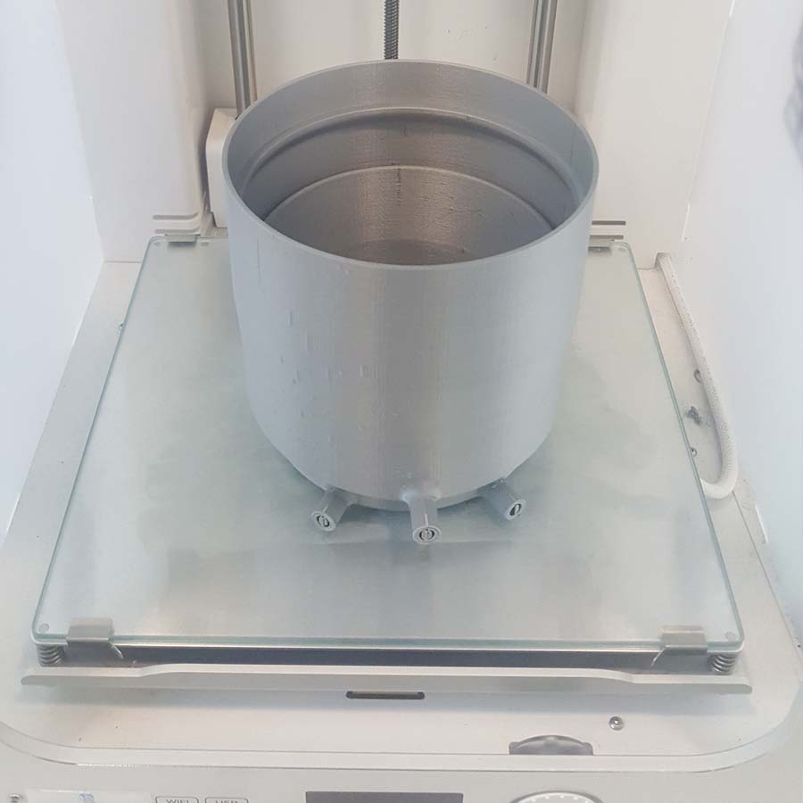
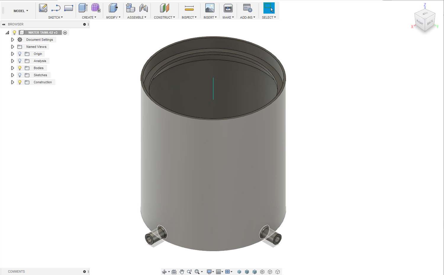
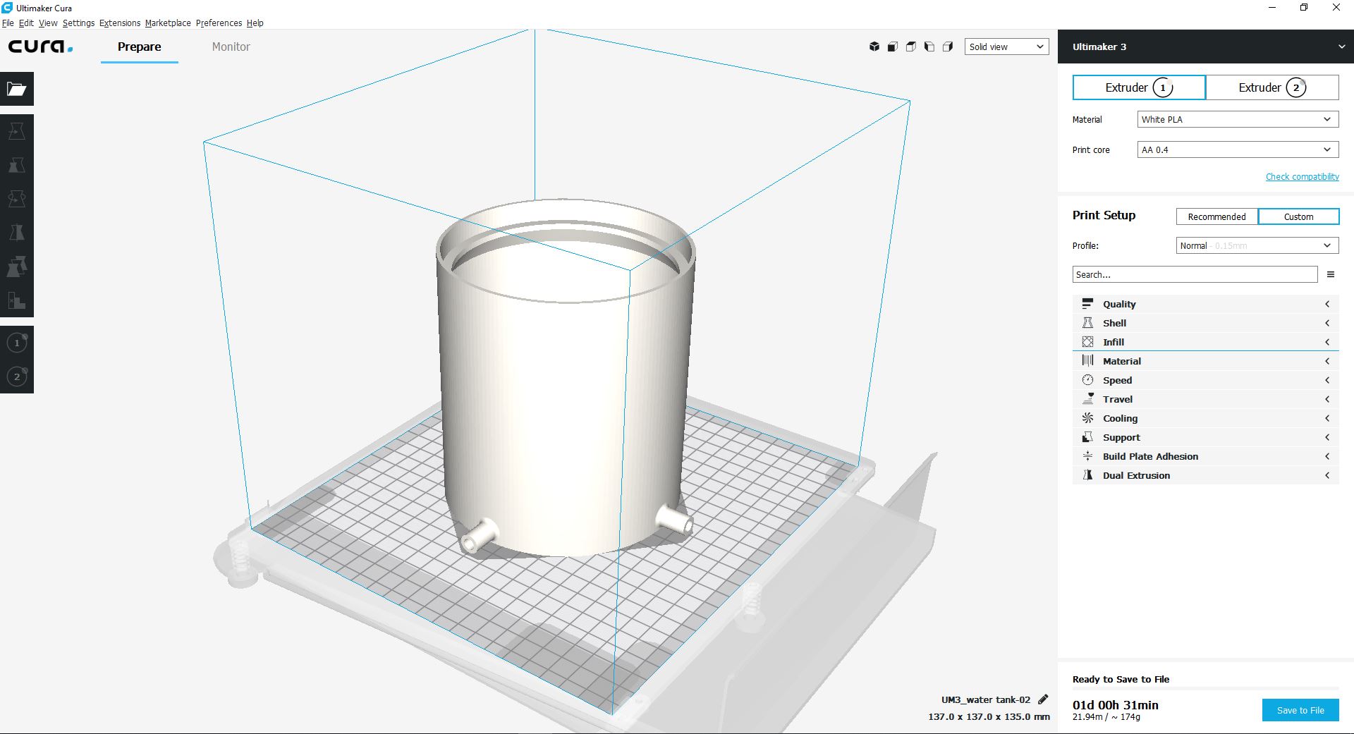
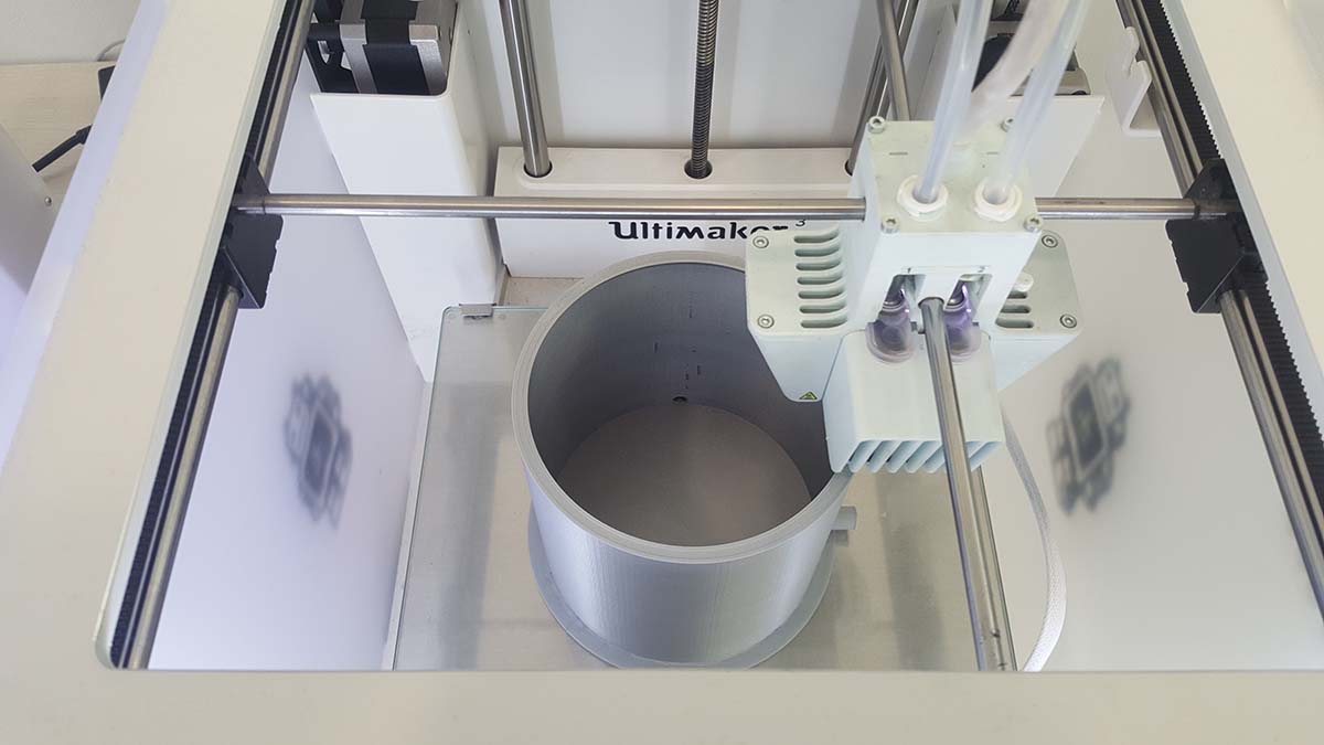
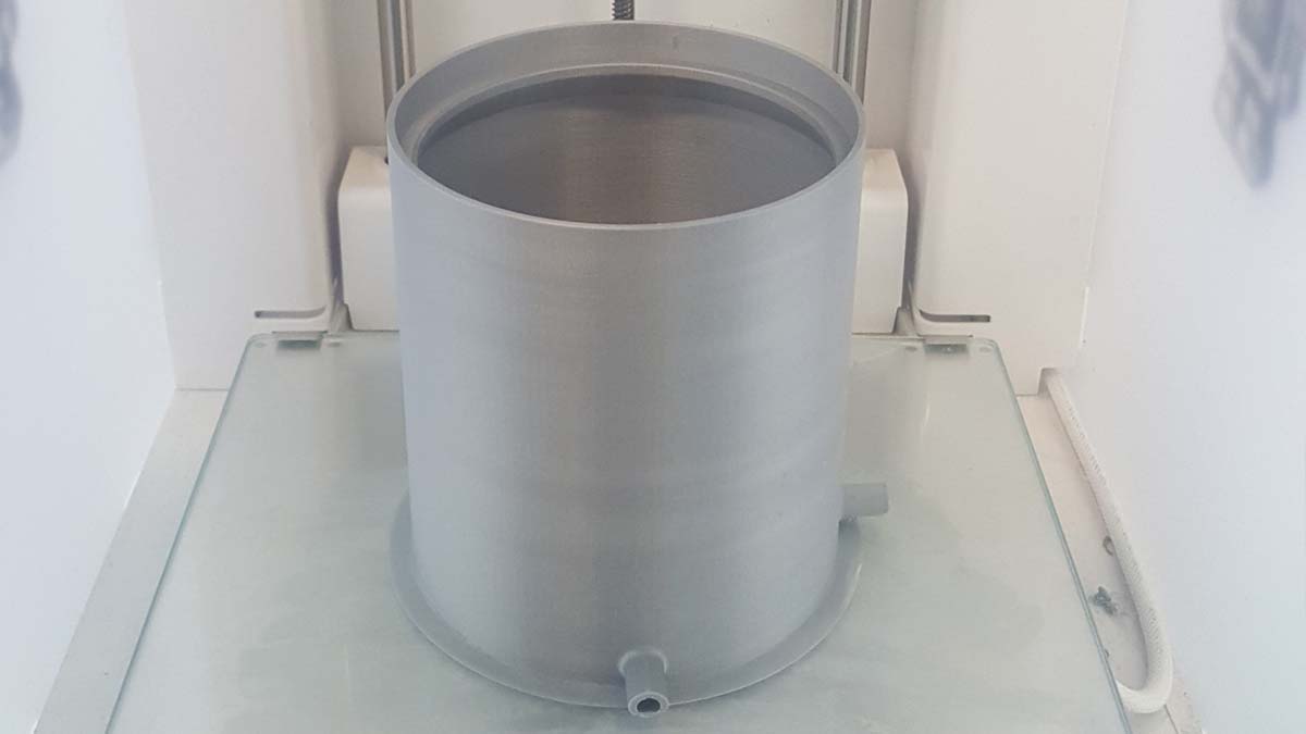
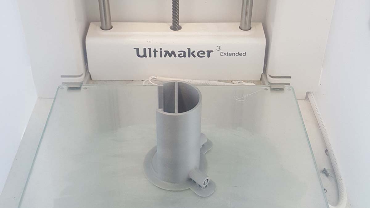
2.4-The Watering System (Water tank and tubing)
The water tank and the water level tank will be 3D printed.
Below is the fusion model
Below is the g-code generation process.
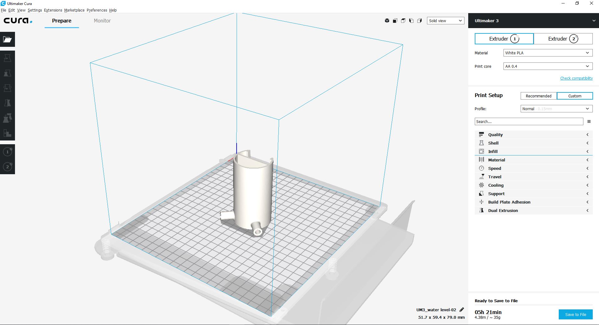
Click Here to download the water-tank STL file.
Click Here to download the water-tank g-code file.
Click Here to download the water-level STL file.
Click Here to download the water-level g-code file.
And here are the production photos
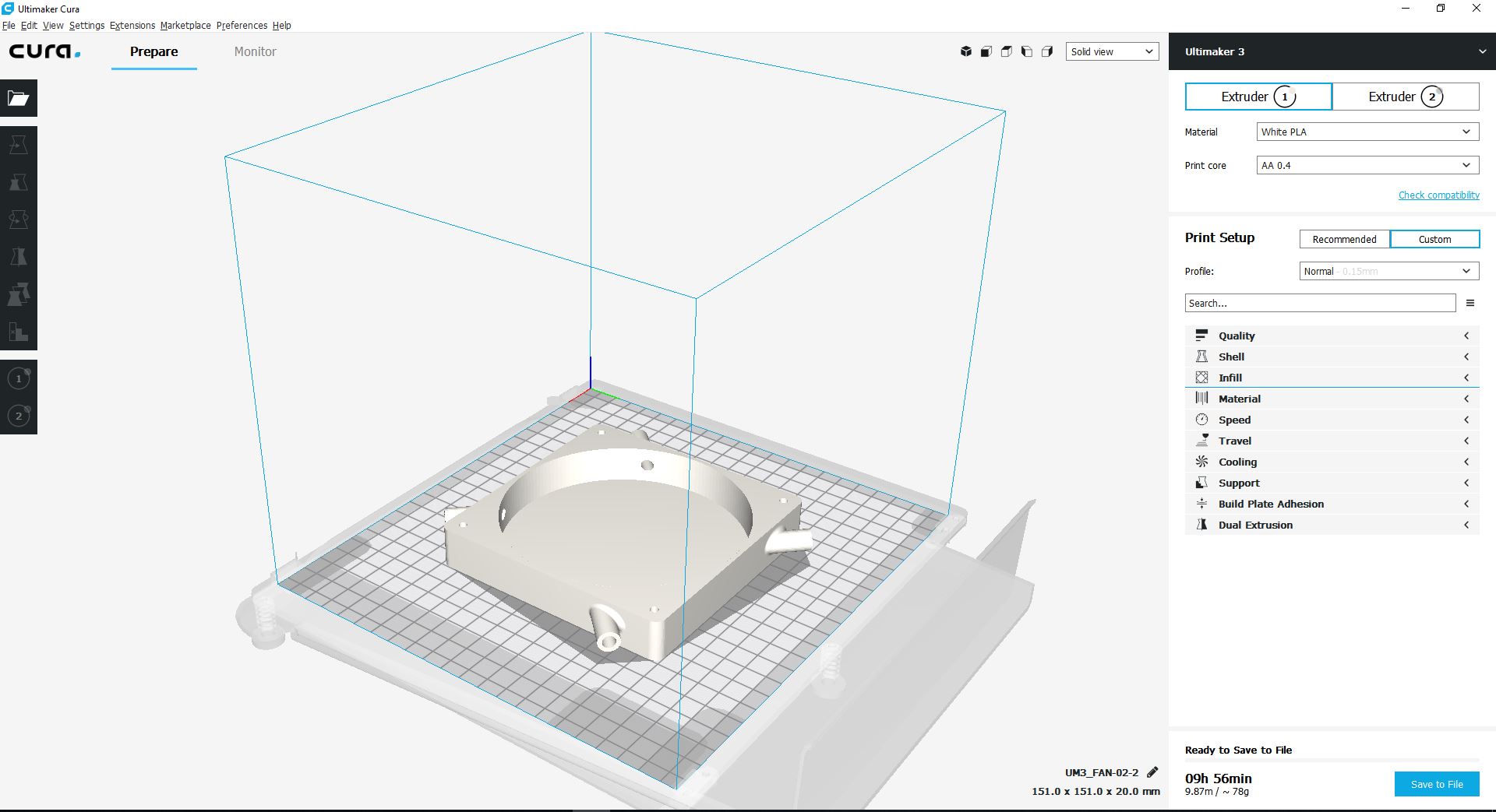
2.5-The Ventilation System (Fan and ducting).
The ventilation ducting connected to the fan will be 3D printed.
Below is the fusion model
Below is the g-code generation process.
Click Here to download the STL file.
Click Here to download the g-code file.
And here are the production photos
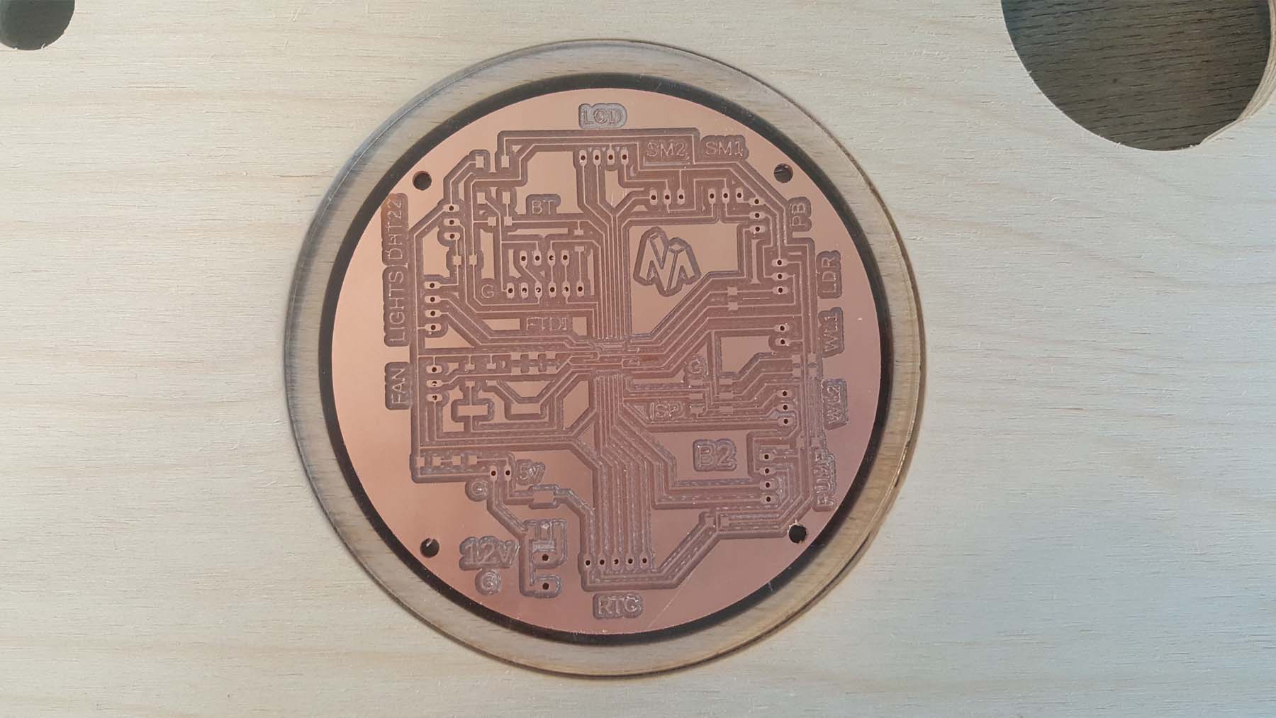
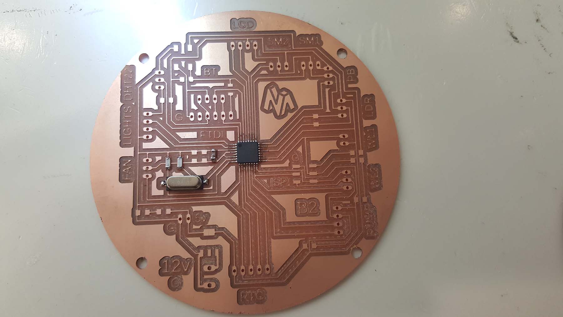
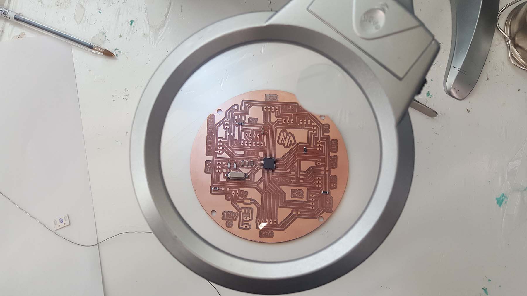
2.6-The Automation System (microcontroller and sensors).
Based on the location of the multiple input/ouput devices distributed on the tray , the PCB board will be designed accordingly.
Refer to W7 Electronic Design for more details about the process.
Refer to W12 Output Device for more details about the process.
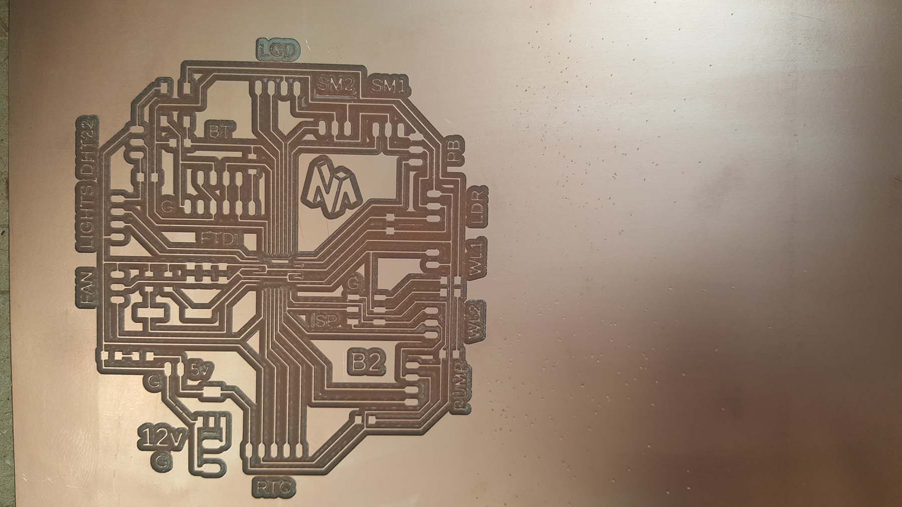
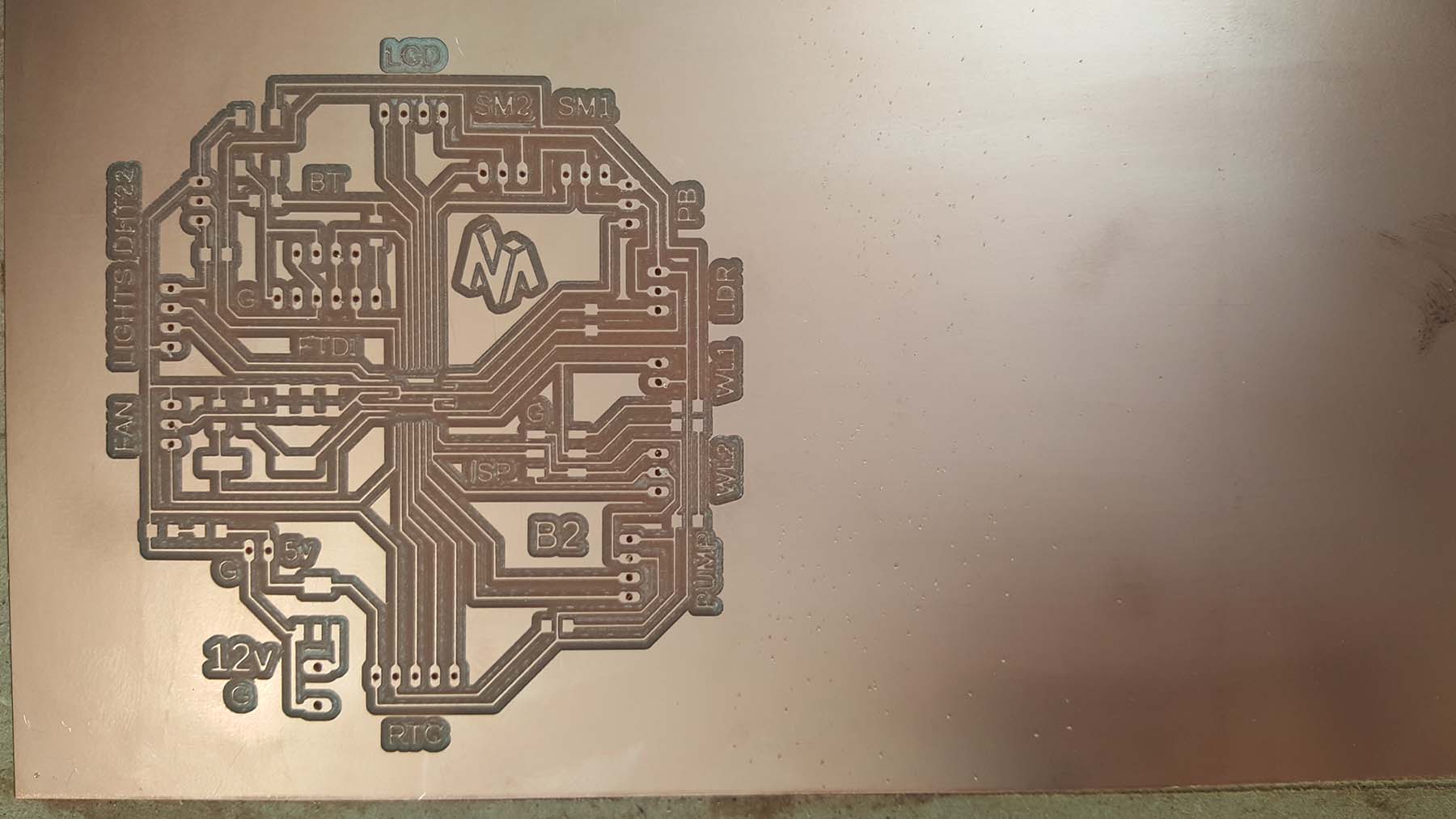
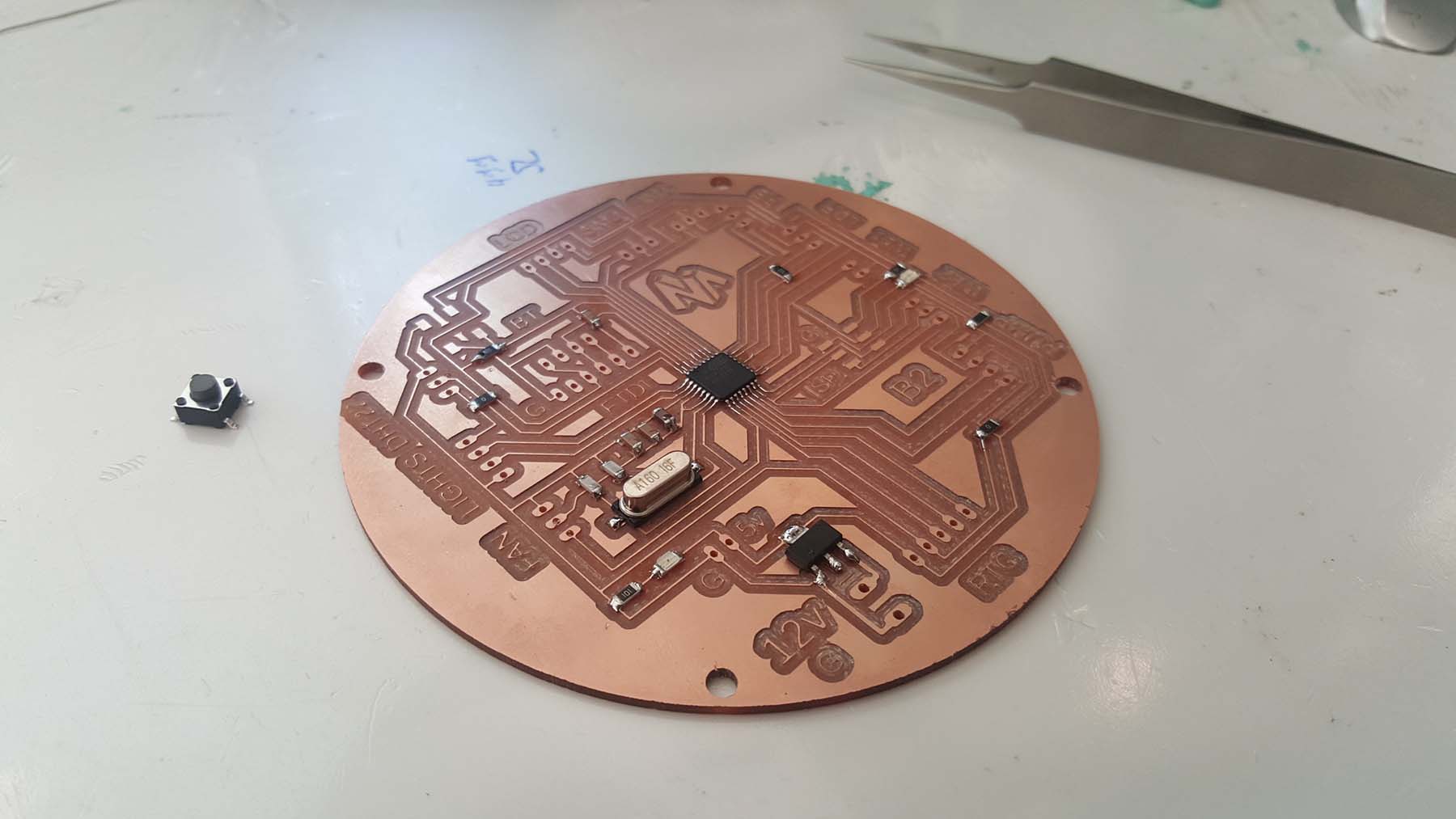
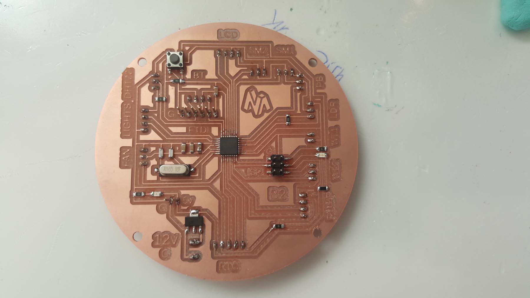
Some modifications and enhancements have been made on my previous B1 Board:
- The Capacitors have been placed the near each others and the nearest to the microcontroller.
- The TX and RX pins have been switched in order to plug the FTDI cable directly to the FTDI pins when programing
- Bluetooth connection pins have been added next to the ftdi pins for future bluetooth connection.
- Ground and VCC pins have been wired to the ISP connection for easier first time programing.
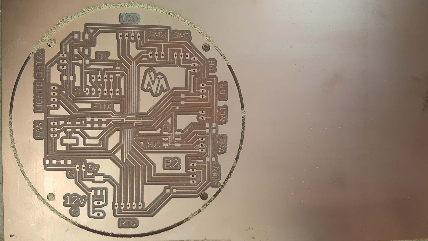
- The shape has been changed to round instead of rectangular to match with my wooden tray design
Below is the Eagle software showing the final sketch and board design:

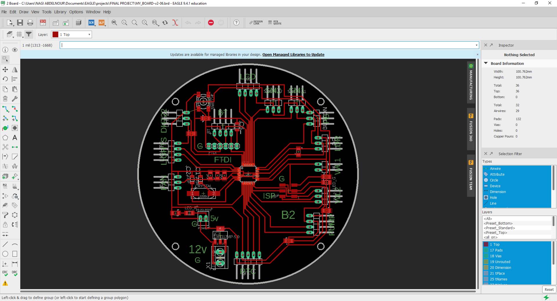
Click Here to download the Eagle file.
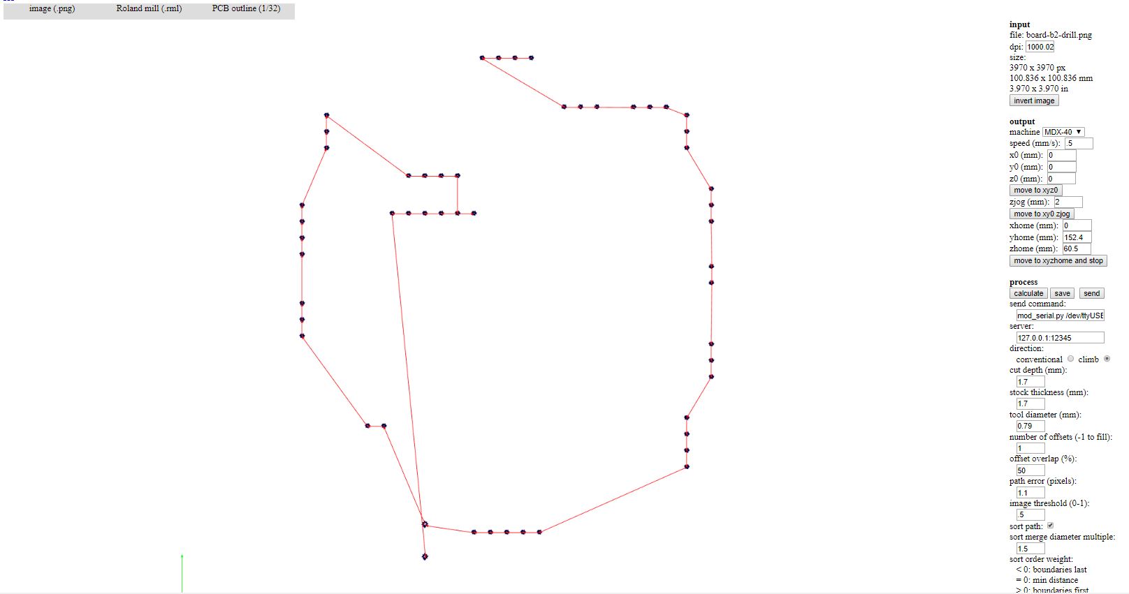
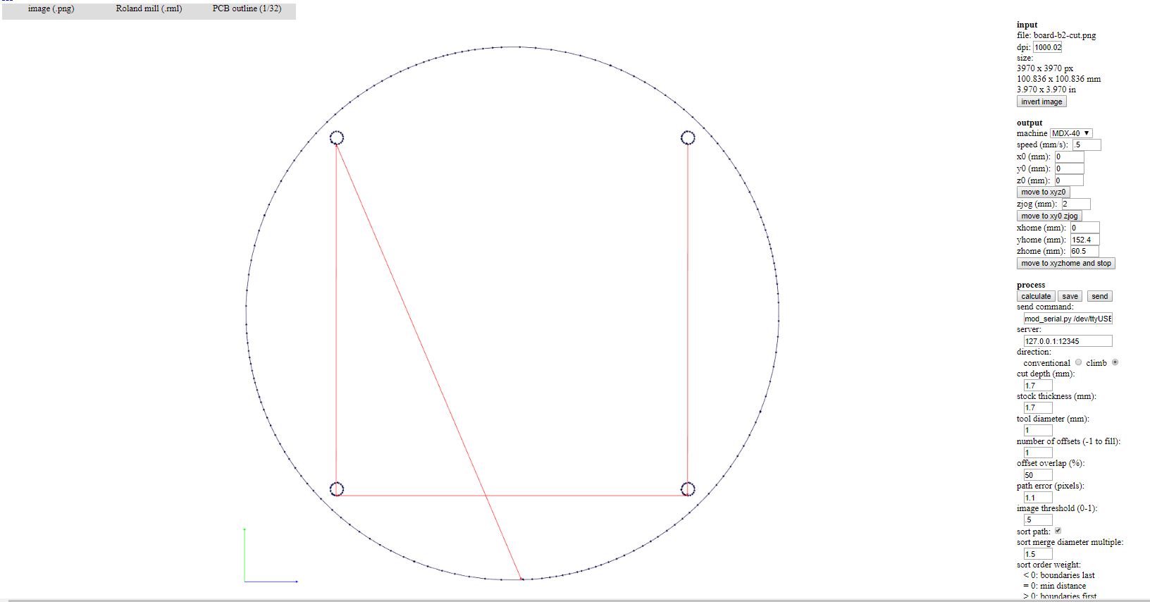
Below is the PCB Traces, Drills and Cutouts
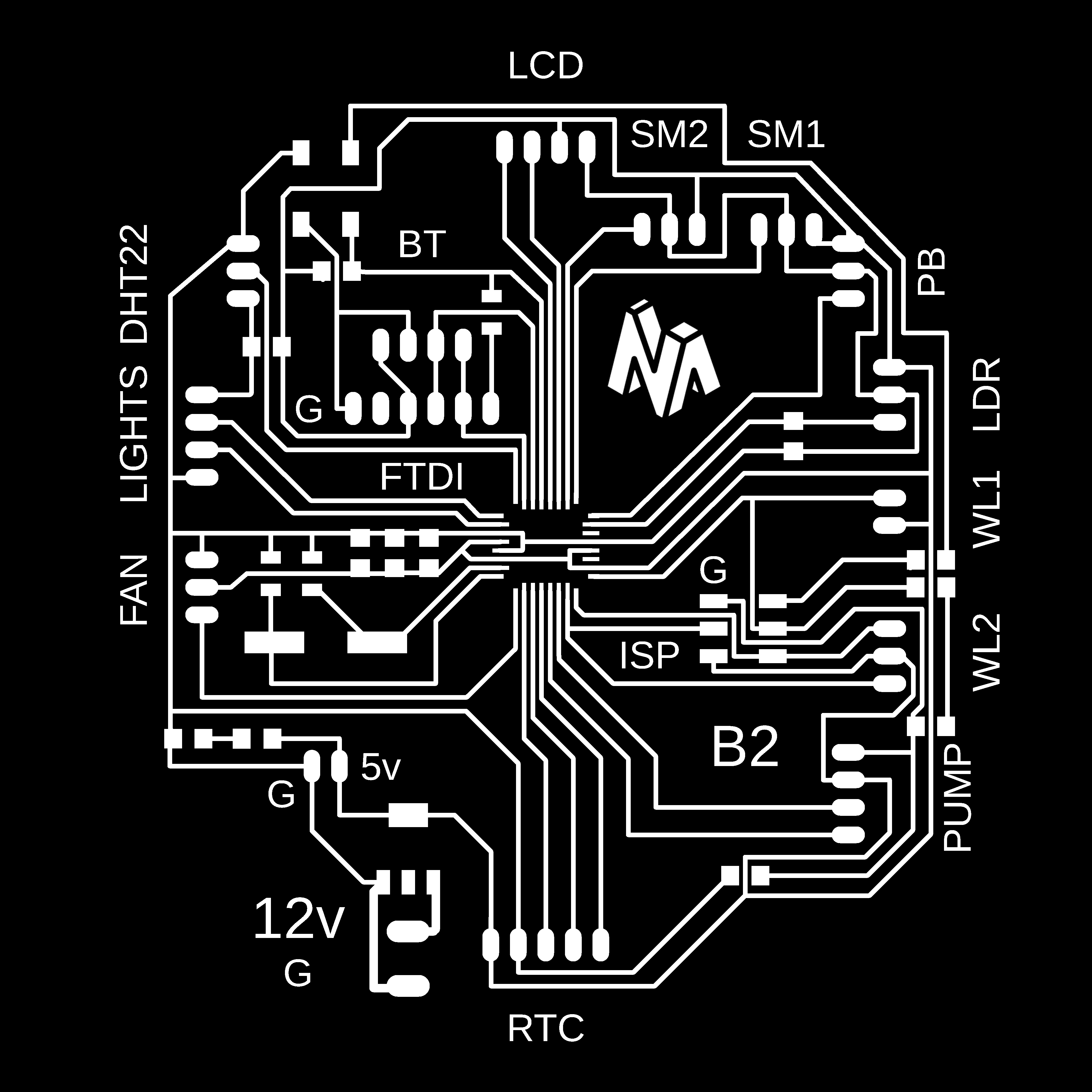

Click Here to download the traces image
Click Here to download the drill image
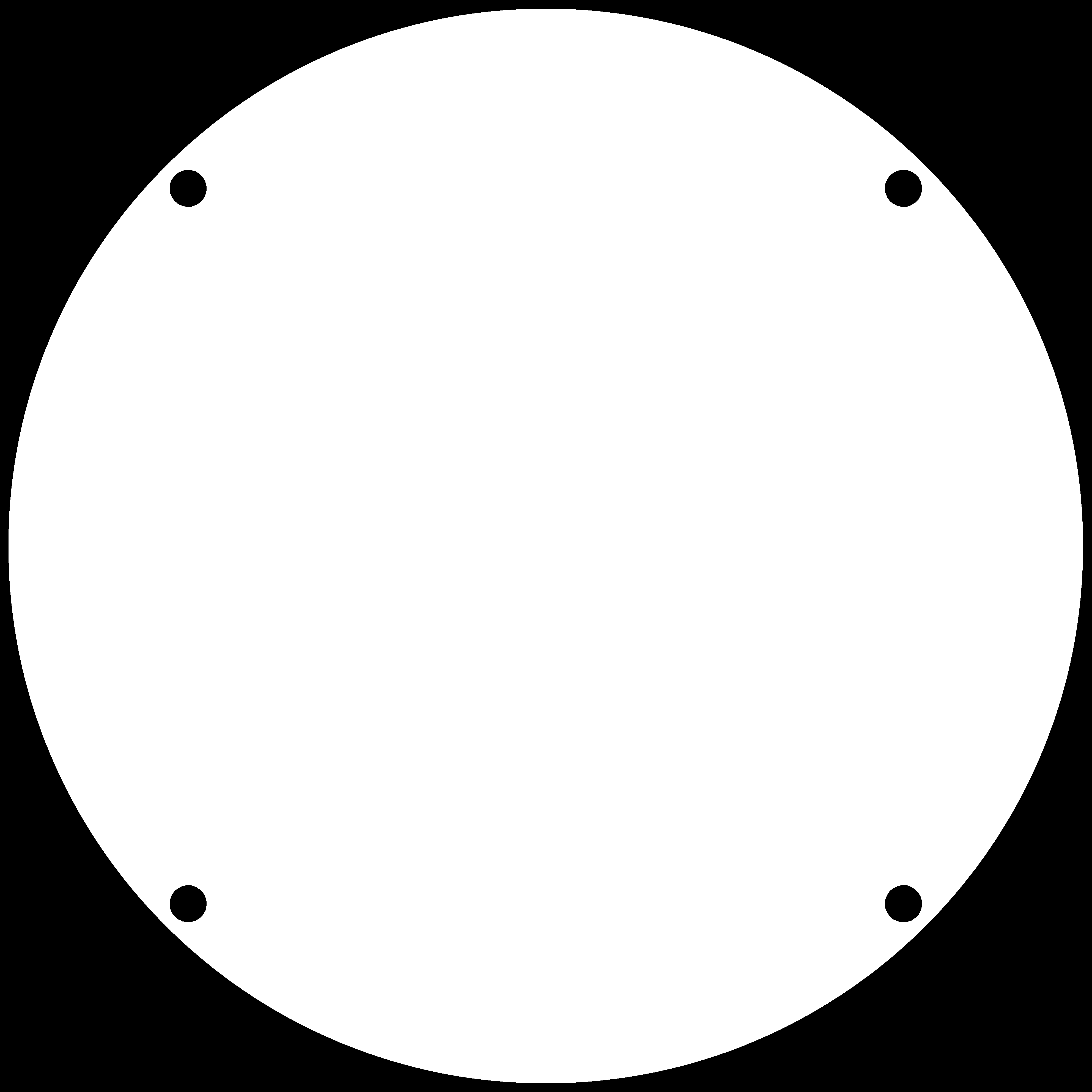
Click Here to download the cutout image
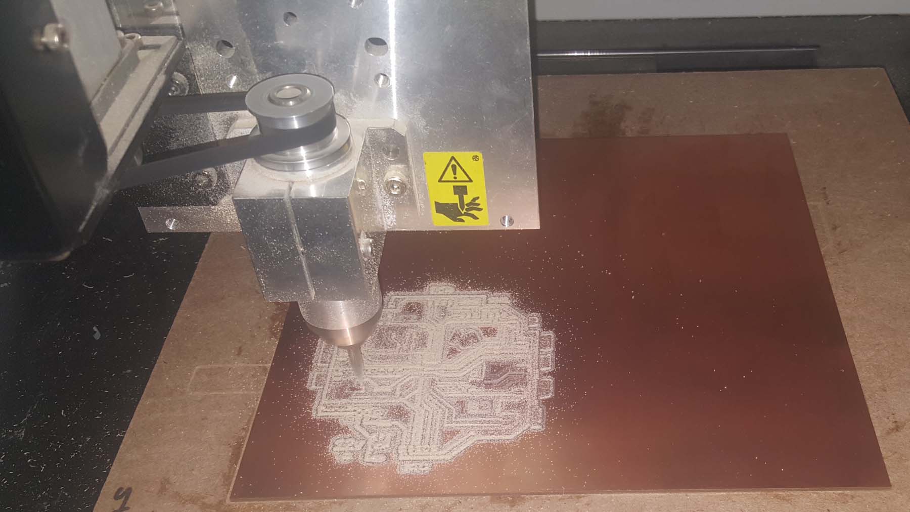
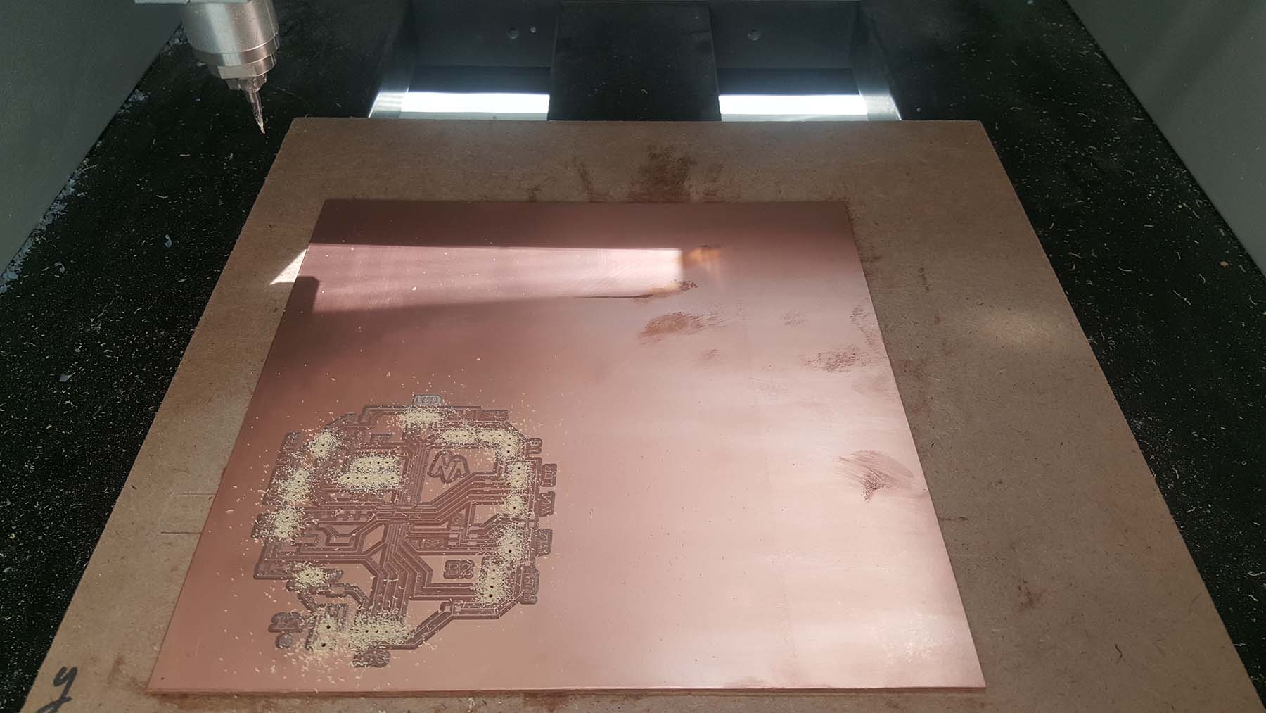
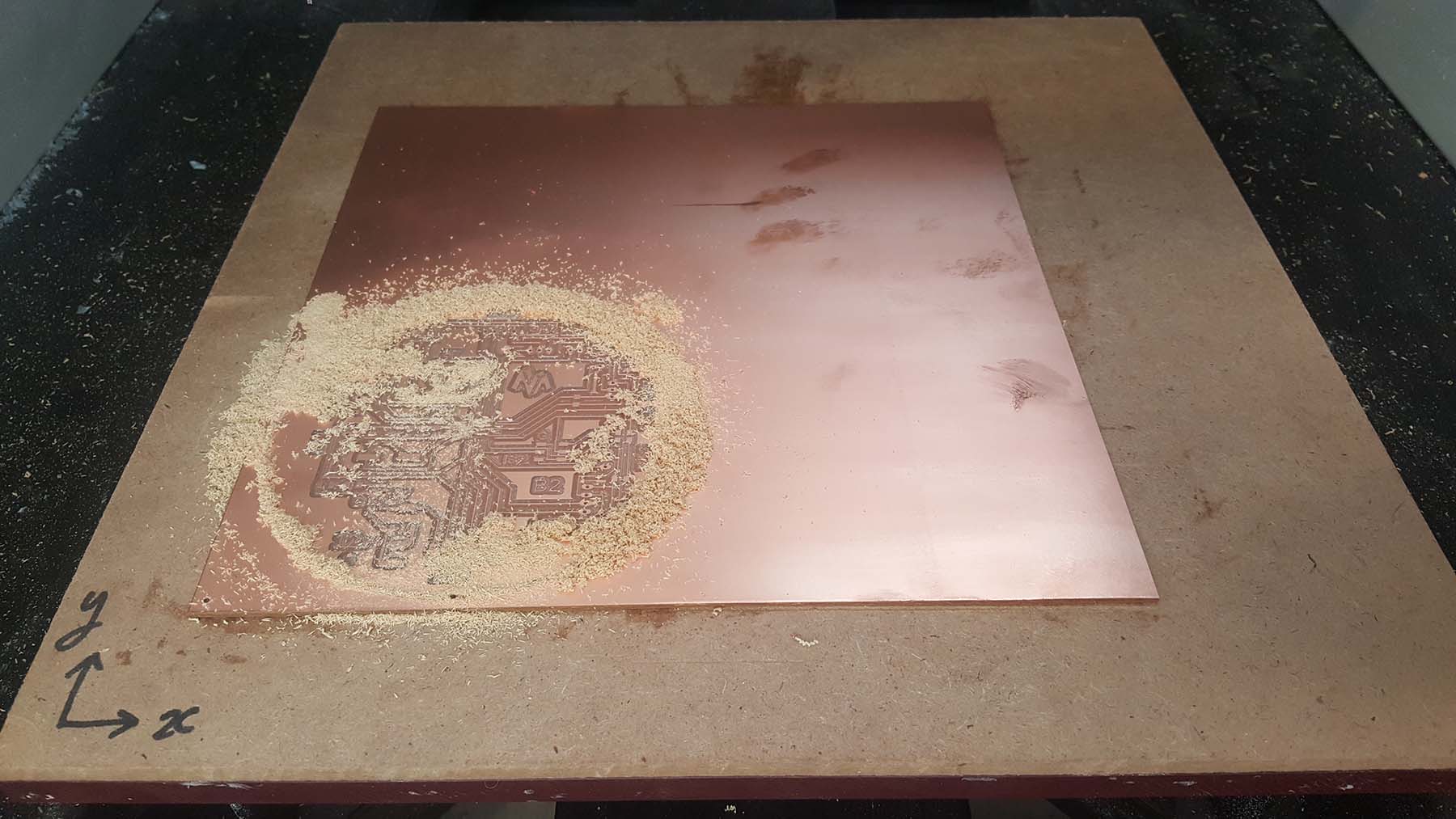
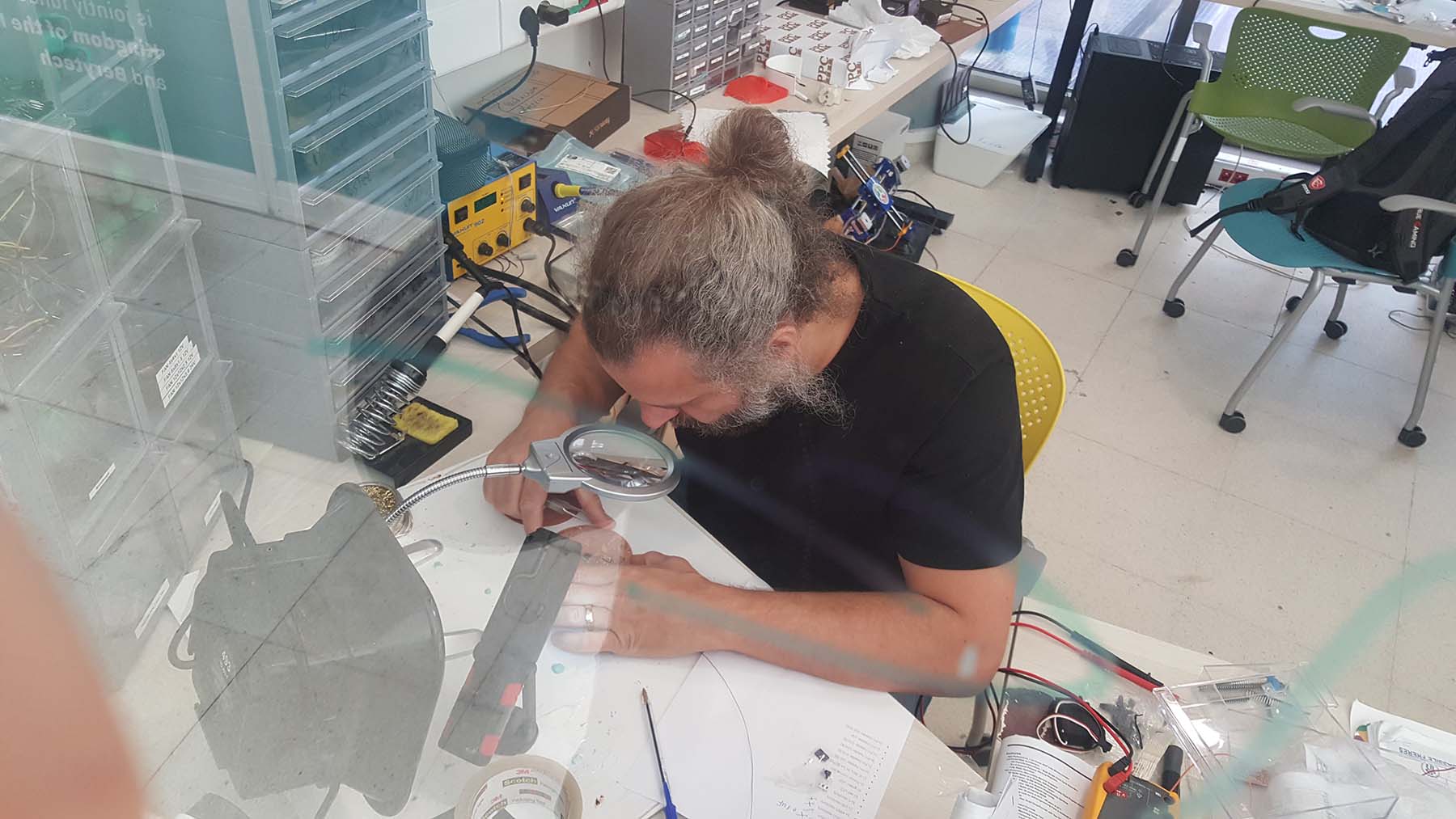
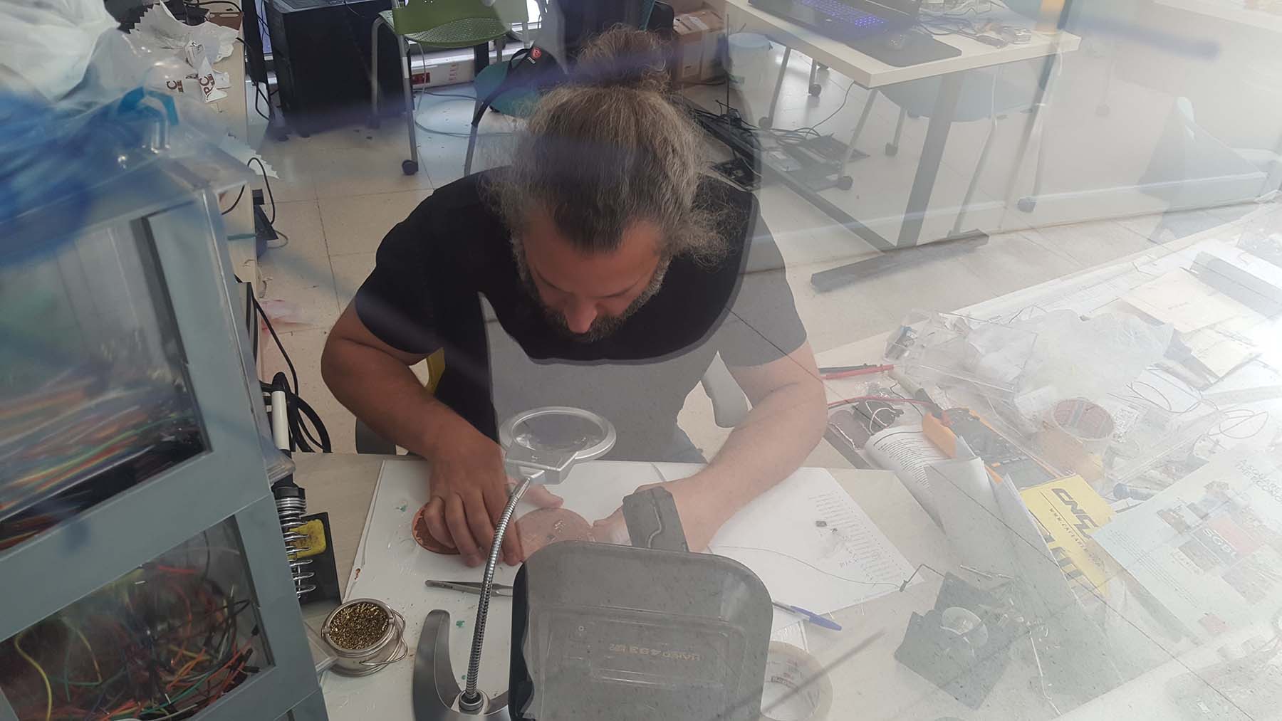
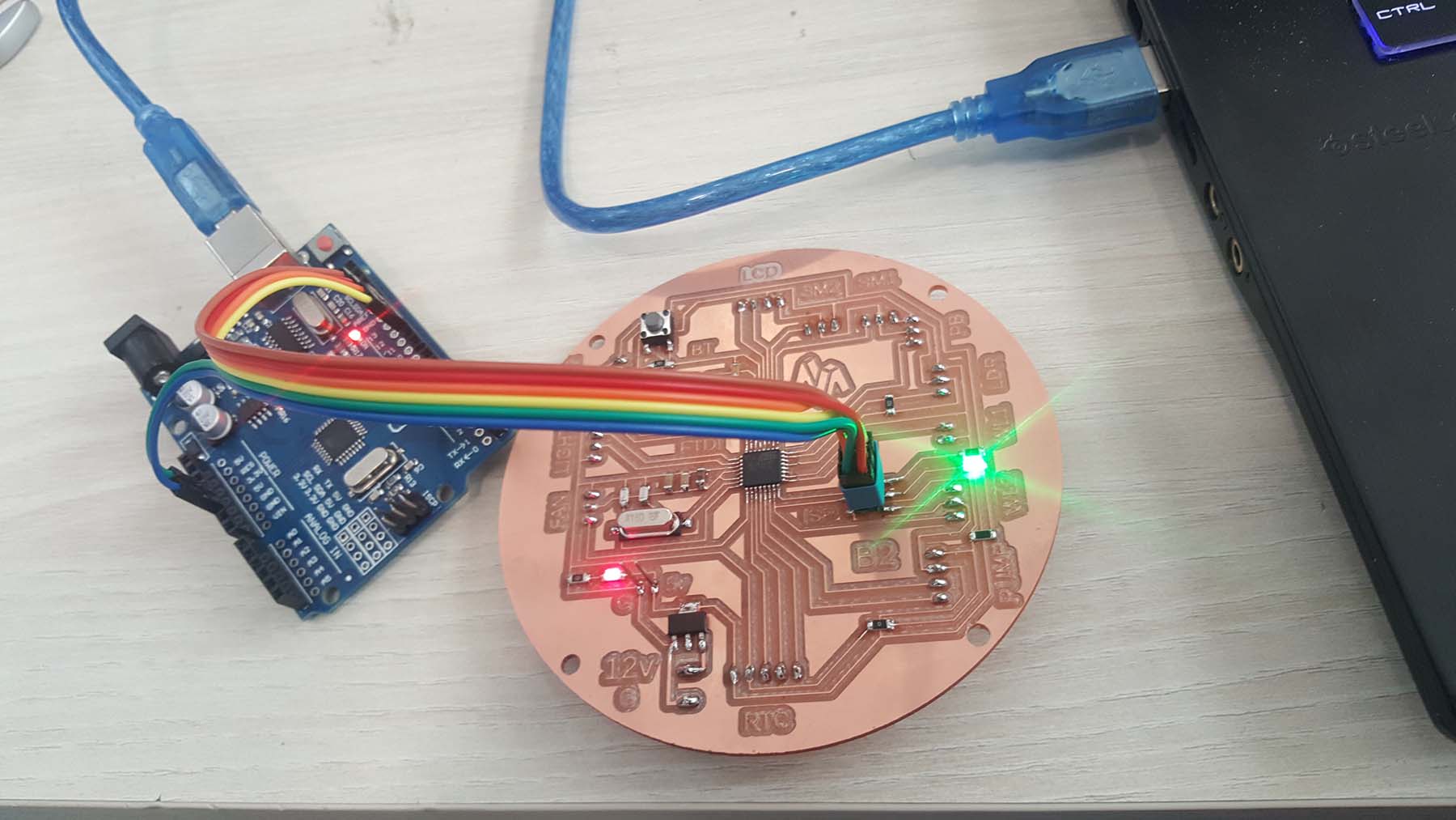
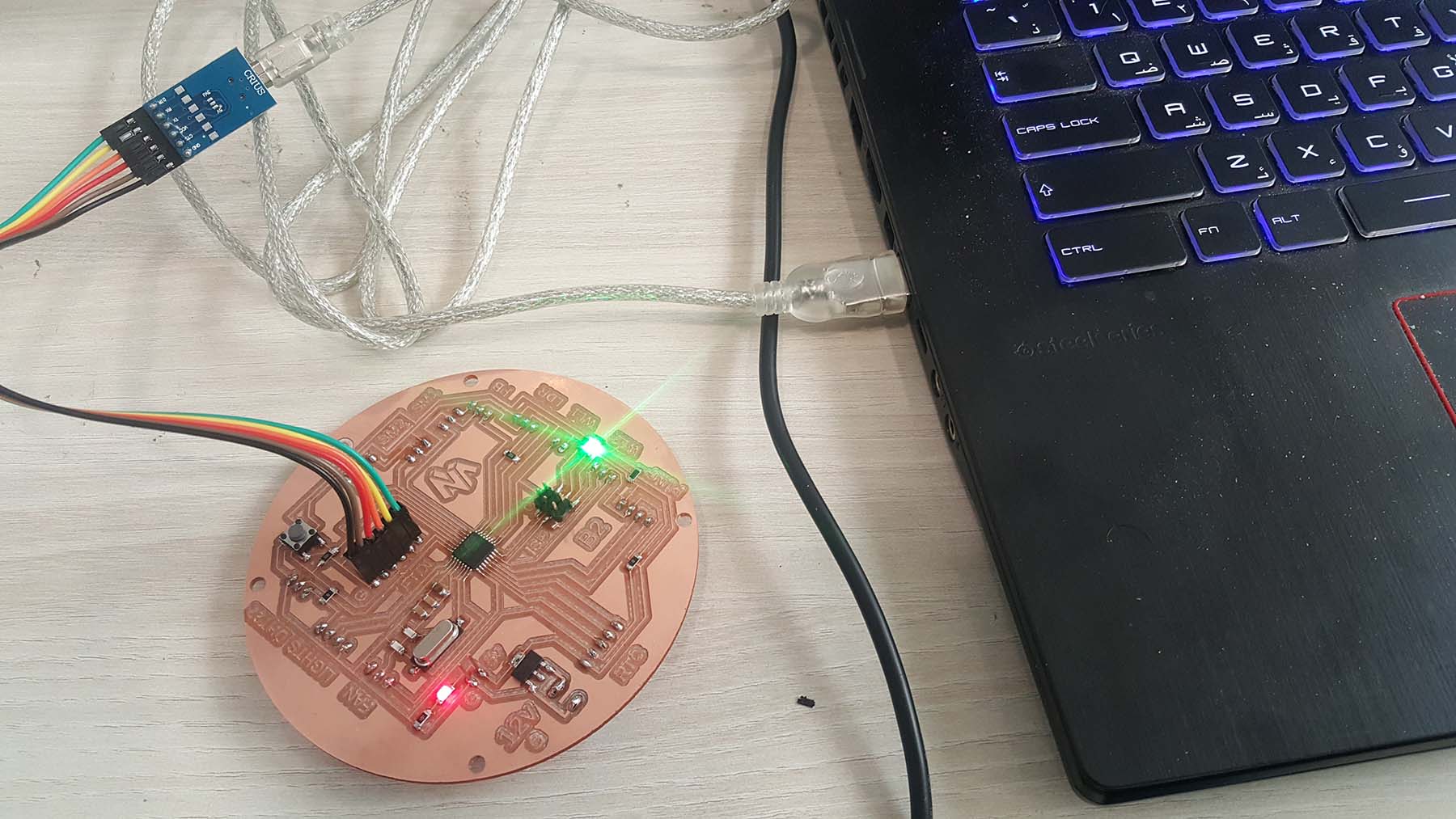
Now I will fabricate the PCB board.
Refer to W5 Electronics Production for more details about the process.
Below are the g-code generation.
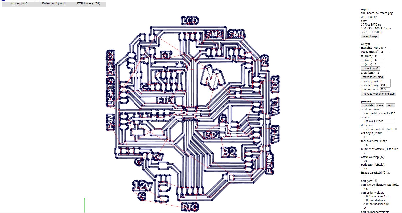
Click Here to download the g-code for milling.
Click Here to download the g-code for drilling.
Click Here to download the g-code for cutting.
Below is the milling, drilling and cutting photos
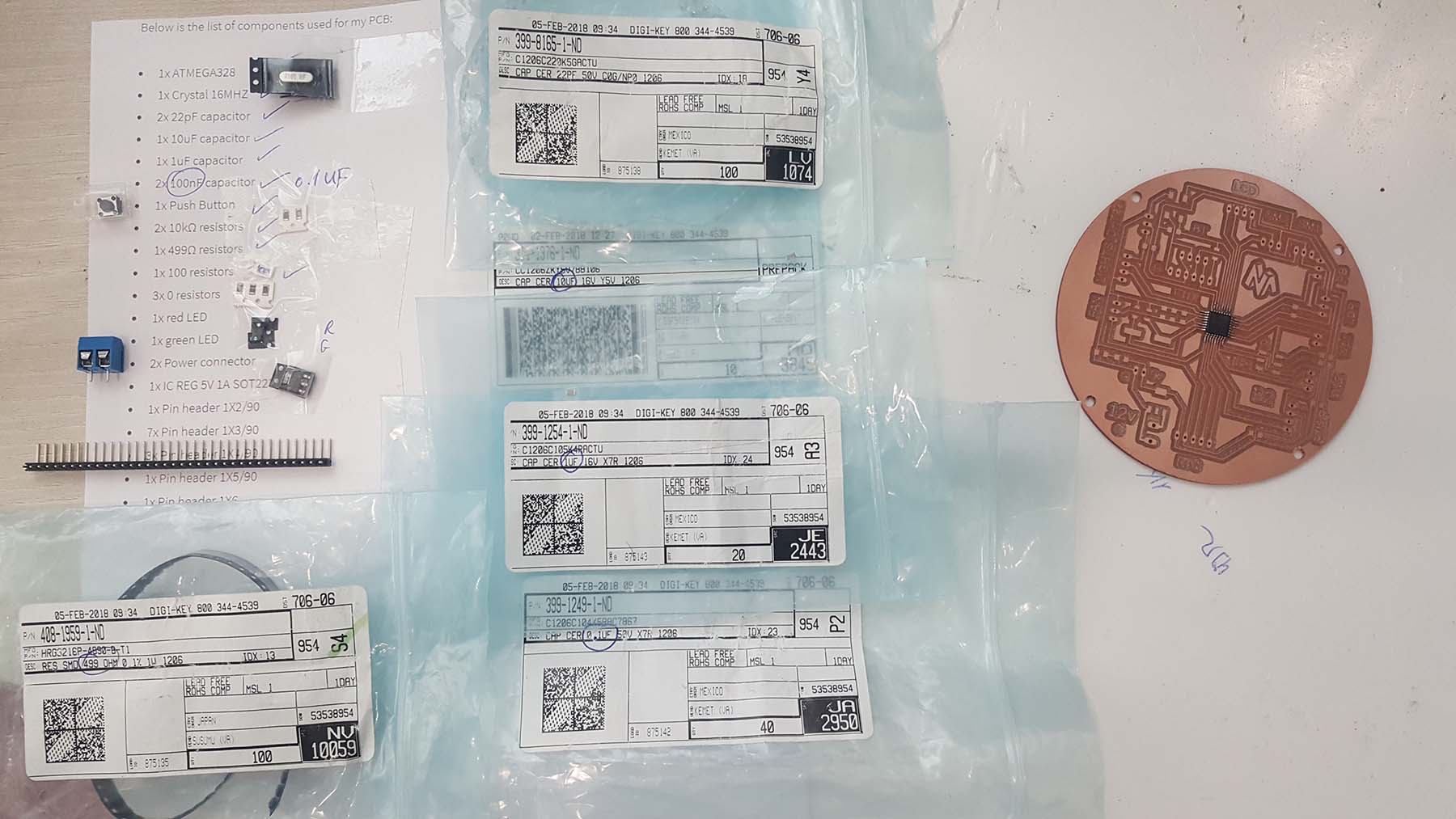
Below is the list of components used for my PCB:
- 1x ATMEGA328
- 1x Crystal 16MHZ
- 2x 22pF capacitor
- 1x 10uF capacitor
- 1x 1uF capacitor
- 2x 100nF capacitor
- 1x Push Button
- 2x 10kΩ resistors
- 1x 499Ω resistors
- 1x 100 resistors
- 3x 0 resistors
- 1x red LED
- 1x green LED
- 2x Power connector
- 1x IC REG 5V 1A SOT223-3
- 1x Pin header 1X2/90
- 7x Pin header 1X3/90
- 3x Pin header 1X4/90
- 1x Pin header 1X5/90
- 1x Pin header 1X6
- 1x Pin header 2X3 SMD
After that comes the welding part.
3-The Programming
After finishing the production of my PCB Board, now I will start the programming.
Refer to W9 Embedded Programming and to W12 Output Device for more details about the process.
First I need to send the bootlder via Arduino as ISP
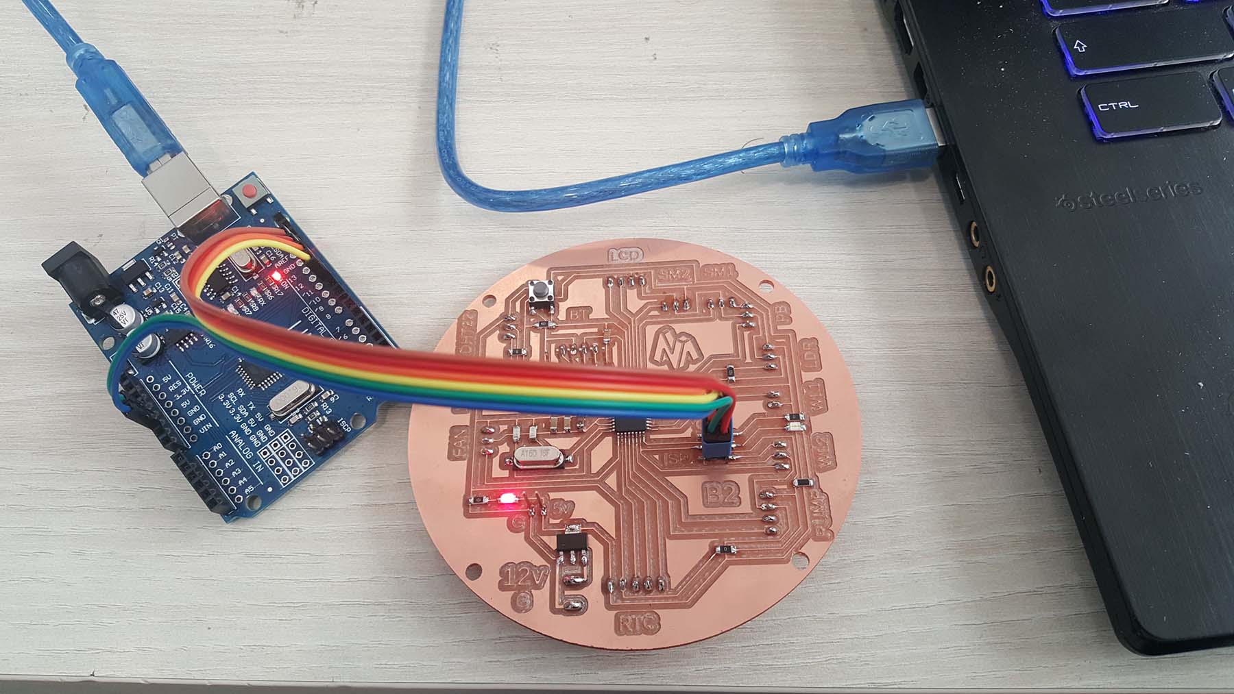
Than I upload the blink test via an Arduino as ISP to test my new board before uploading my final program
Now I have to send the bootloader again and test my FTDI connection directly (after bootloader I should not programm via Arduino as ISP) or the FTDI WON'T WORK
Here I will upload the blink test via FTDI
Everything is working great and now I can upload my final program
                        /*Impport following Libraries*/
#include
#include
LiquidCrystal_I2C lcd(0x3f, 2, 1, 0, 4, 5, 6, 7, 3, POSITIVE);
// Load the virtuabotixRTC library
#include
// myRTC (clock, data, RST)
virtuabotixRTC myRTC (6, 7, 8);
//Load the DHT library
#include
dht DHT;
#define DHT22_PIN 2

/*Variables*/
float hum;
float temp;

/*Setting the Pins */
int lightPin = 0;
int wSensor = A1;
int soilPin1 = A2;
int soilPin2 = A3;
int pushButton = 11;

const int Green_LED_PIN = 13;

int relayPinL1 = 3;
int relayPinL2 = 4;
int relayPinF = 5;
int relayPinP1 = 9;
int relayPinP2 = 10;

int sm1percentValue = 0;


unsigned long Screen_timestamp;
int Screen_case = 0;

unsigned long Drain_Timestamp;
unsigned long Irrig_Timestamp;

int Drain_Percentage = 0;
int Irrig_Percentage = 0;

#define Drain_Pin 10
#define Irrig_Pin 9


void setup()

{
  Serial.begin(9600);
  pinMode(lightPin, INPUT);
  pinMode(wSensor, INPUT);
  pinMode(pushButton, INPUT); digitalWrite(pushButton, HIGH);
  pinMode(soilPin1, INPUT);
  pinMode(soilPin2, INPUT);

  pinMode(13, OUTPUT);

  pinMode(relayPinF, OUTPUT);
  pinMode(relayPinL1, OUTPUT);
  pinMode(relayPinL2, OUTPUT);
  pinMode(relayPinP1, OUTPUT);
  pinMode(relayPinP2, OUTPUT);

  //Turn OFF any power to the Relay channels
  digitalWrite(relayPinF, LOW);
  digitalWrite(relayPinL1, HIGH);
  digitalWrite(relayPinL2, HIGH);
  digitalWrite(relayPinP1, HIGH);
  digitalWrite(relayPinP2, HIGH);
  delay(2000);


  lcd.begin(16, 2);
  lcd.backlight();
  //lcd.backlight();

  // After to set the entire information, comment the following line
  // (seconds, minutes, hours, day of week, day of month, month, year)
  //myRTC.setDS1302Time (50, 36, 14, 4, 14, 6, 2019);

  pinMode(Drain_Pin, OUTPUT);
  pinMode(Irrig_Pin, OUTPUT);
  digitalWrite(Drain_Pin, HIGH);


}

void Irrig_Drain() {
  if (Drain_Percentage == 0) digitalWrite(Drain_Pin, HIGH);
  if (Drain_Percentage == 20) digitalWrite(Drain_Pin, LOW);
  if (Drain_Percentage > 0 && Drain_Percentage < 20) {
    if (digitalRead(Drain_Pin) == LOW) {
      if (millis() - Drain_Timestamp > (Drain_Percentage) * 1000) {
        digitalWrite(Drain_Pin, HIGH);
        Drain_Timestamp = millis();
      }
    }
    else {
      if (millis() - Drain_Timestamp > (20 - Drain_Percentage) * 1000) {
        digitalWrite(Drain_Pin, LOW);
        Drain_Timestamp = millis();
      }
    }
  }

  if (Irrig_Percentage == 0) digitalWrite(Irrig_Pin, HIGH);
  if (Irrig_Percentage == 20) digitalWrite(Irrig_Pin, LOW);
  if (Irrig_Percentage > 0 && Irrig_Percentage < 20) {
    if (digitalRead(Irrig_Pin) == LOW) {
      if (millis() - Irrig_Timestamp > (Irrig_Percentage) * 1000) {
        digitalWrite(Irrig_Pin, HIGH);
        Irrig_Timestamp = millis();
      }
    }
    else {
      if (millis() - Irrig_Timestamp > (20 - Irrig_Percentage) * 1000) {
        digitalWrite(Irrig_Pin, LOW);
        Irrig_Timestamp = millis();
      }
    }
  }
}


void loop()
{
  while (Serial.available())
  {
    char inChar = (char)Serial.read();

    switch (inChar)
    {
      case '1':
        digitalWrite(relayPinL2, LOW);
        break;

      case '0':
        digitalWrite(relayPinL2, HIGH);
        break;

      case '2':
        digitalWrite(Green_LED_PIN, HIGH);
        break;

      case '4':
        digitalWrite(Green_LED_PIN, LOW);
        break;

      case 'A':
        digitalWrite(relayPinF, HIGH);
        break;

      case 'B':
        digitalWrite(relayPinF, LOW);
        break;
      case '7':
        digitalWrite(relayPinL1, LOW);
        break;

      case '8':
        digitalWrite(relayPinL1, HIGH);
        break;

    }
  }


  delay(200);
  Irrig_Drain();
  /*Reads the information from the CI */
  myRTC.updateTime ();

  /*dht control */
  int chk = DHT.read22(DHT22_PIN);//Read data and store it to variables hum and temp
  hum = DHT.humidity;
  temp = DHT.temperature;

  /*Reading vlues from sensors */
  int ldr = analogRead(lightPin);
  int wl = analogRead(wSensor);
  int sm1 = analogRead(soilPin1);
  int sm2 = analogRead(soilPin2);
  int sm = (sm1 + sm2) / 2;


  if (digitalRead(pushButton) == LOW) {
    Screen_timestamp = millis();
    Screen_case++;
    if (Screen_case > 3 ) Screen_case = 0;
    delay(30);
  }
  if (millis() - Screen_timestamp > 5000) { //to change the time display
    Screen_timestamp = millis();
    Screen_case++;
    if (Screen_case > 3 ) Screen_case = 0;

  }

  if (Screen_case == 0) {
    /*LCD control */
    lcd.clear();
    lcd.setCursor(0, 0);
    lcd.print("LDR VALUE ");
    lcd.setCursor(12, 0);
    lcd.print(ldr);
  }


  if (Screen_case == 1) {
    lcd.clear();
    lcd.setCursor(0, 0);
    lcd.print("Temp         C  ");
    lcd.setCursor(6, 0);
    lcd.print(temp);
    lcd.setCursor(0, 1);
    lcd.print("Hum          %  ");
    lcd.setCursor(6, 1);
    lcd.print(hum);
  }

  if (Screen_case == 2) {
    lcd.clear();
    lcd.setCursor(0, 0);
    lcd.print("Soil_m 1:       ");
    lcd.setCursor(12, 0);
    lcd.print(analogRead(soilPin1));
    lcd.setCursor(0, 1);
    lcd.print("Soil_m 2:       ");
    lcd.setCursor(12, 1);
    lcd.print(analogRead(soilPin2));
  }

  if (Screen_case == 3) {
    lcd.clear();
    lcd.setCursor(0, 0);
    lcd.print("TIME  ");

    lcd.setCursor(6, 0);
    if (myRTC.hours <= 9) {
      lcd.setCursor(6, 0);
      lcd.print("0");
      lcd.setCursor(7, 0);
      lcd.print(myRTC.hours);
    }
    else {
      lcd.print(myRTC.hours);
    }

    lcd.setCursor(8, 0);
    lcd.print(":");

    lcd.setCursor(9, 0);
    if (myRTC.minutes <= 9) {
      lcd.setCursor(9, 0);
      lcd.print("0");
      lcd.setCursor(10, 0);
      lcd.print(myRTC.minutes);
    }
    else {
      lcd.print(myRTC.minutes);
    }

    lcd.setCursor(0, 1);
    lcd.print("DATE    .  .     ");

    lcd.setCursor(6, 1);
    if (myRTC.dayofmonth <= 9) {
      lcd.setCursor(6, 1);
      lcd.print("0");
      lcd.setCursor(7, 1);
      lcd.print(myRTC.dayofmonth);
    }
    else {
      lcd.print(myRTC.dayofmonth);
    }

    lcd.setCursor(9, 1);
    if (myRTC.month <= 9) {
      lcd.setCursor(9, 1);
      lcd.print("0");
      lcd.setCursor(10, 1);
      lcd.print(myRTC.month);
    }
    else {
      lcd.print(myRTC.month);
    }

    lcd.setCursor(12, 1);
    lcd.print(myRTC.year);
  }


  /*relay control L1 */
  //if ((myRTC.hours >= 8) && (myRTC.hours <= 18))
  //  {
  //digitalWrite(relayPinL1 , HIGH);
  //}
  //else
  //{
  //digitalWrite(relayPinL1 , LOW);
  //}


  /*relay control P1 PUMP1 FOR WATERING */
  if (sm < 500)
  {
    Irrig_Percentage = 5;
  }

  if (wl > 600) Irrig_Percentage = 0;


  if (sm > 600)
  {
    Drain_Percentage = 5;
  }

  if (wl < 425) Drain_Percentage = 0;

  /*Printing values on serial*/

  Serial.print("sm1 = ");
  Serial.println(sm1);
  Serial.print("sm2 = ");
  Serial.println(sm2);
  Serial.print("sm = ");
  Serial.println(sm);
  //delay(500);
  Serial.print("Water level = ");
  Serial.println(wl);


}
Click Here to download the Code.
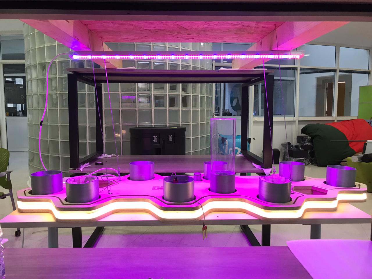
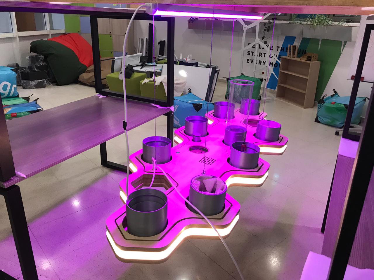
4-The Assembly
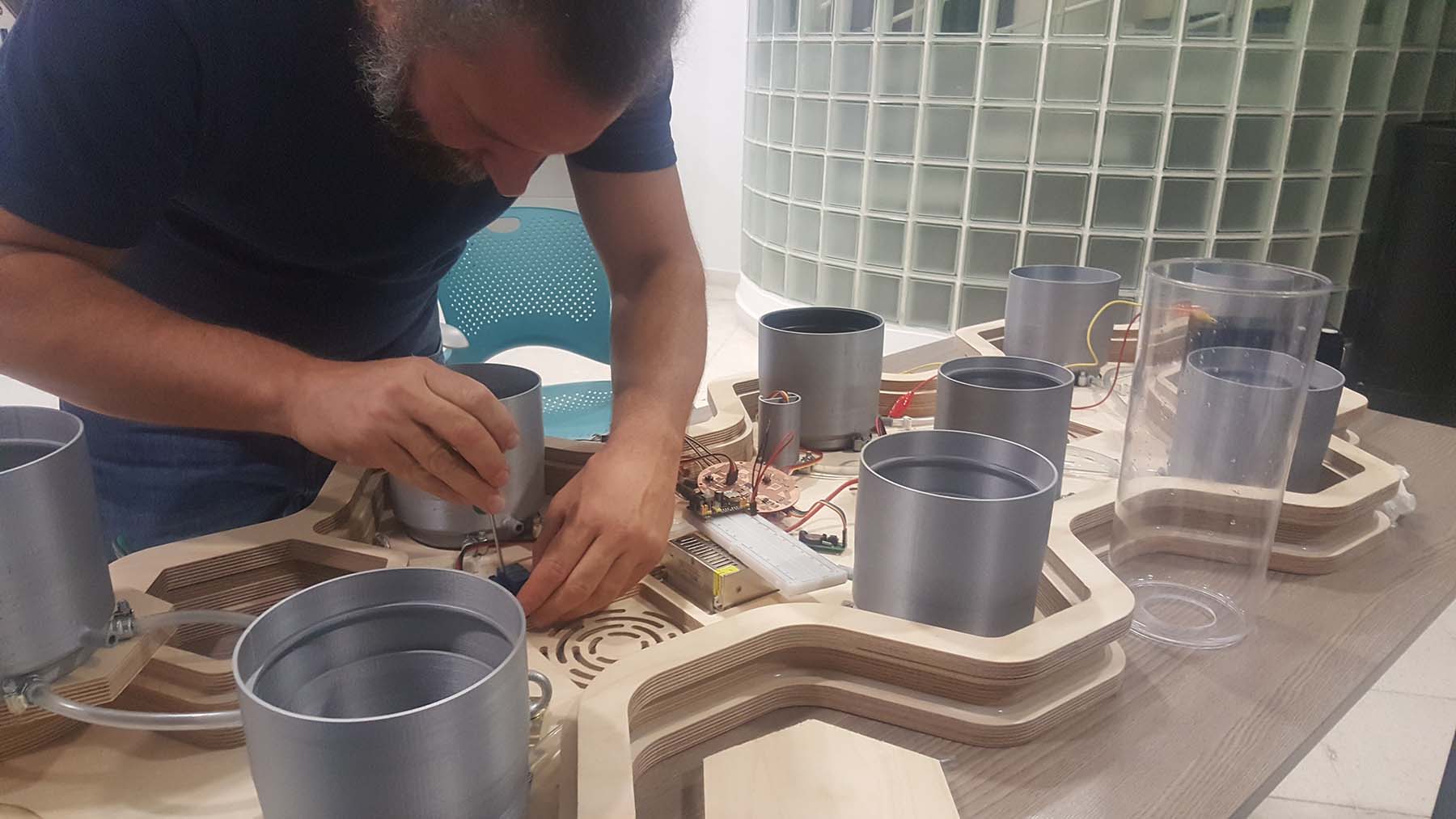
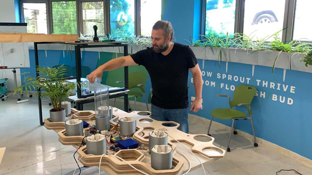
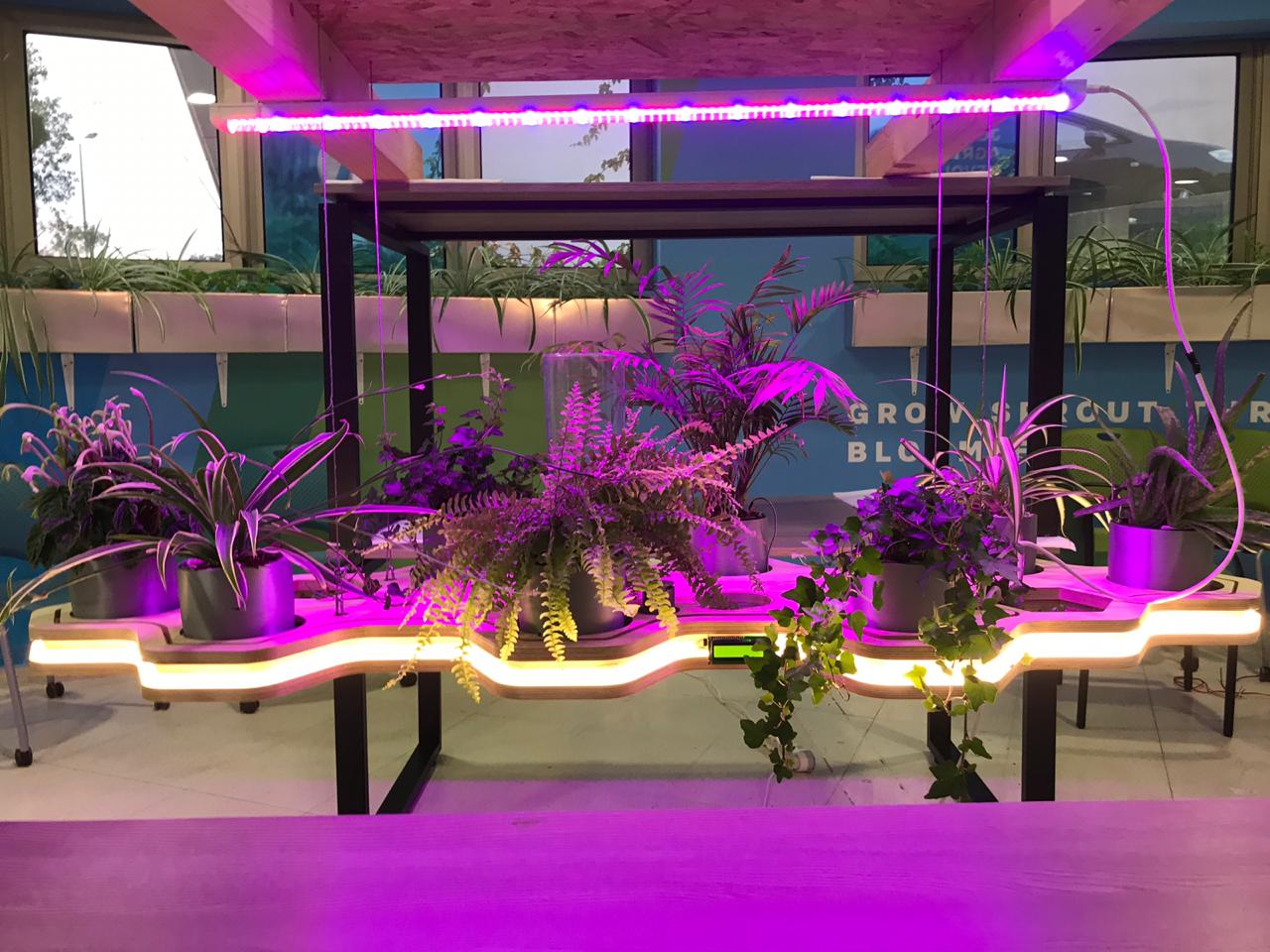
Now that all the parts are ready , I will start the assembly.
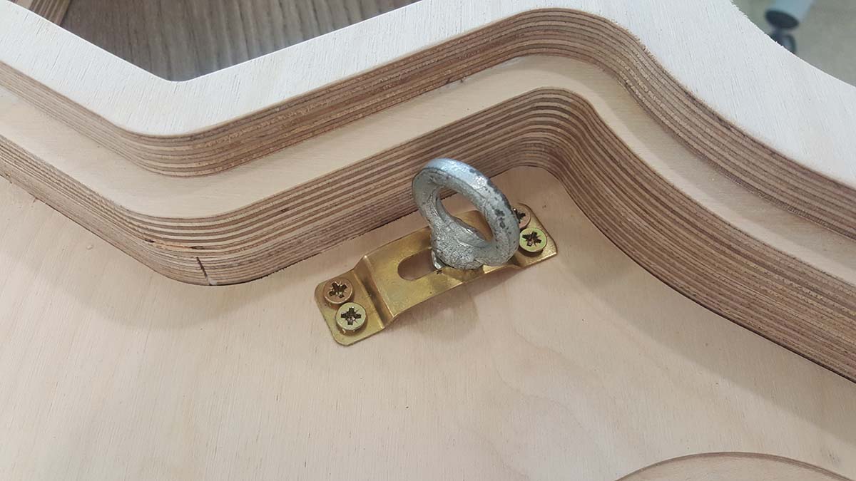
Assembling the wooden tray
Assembling the cable supports
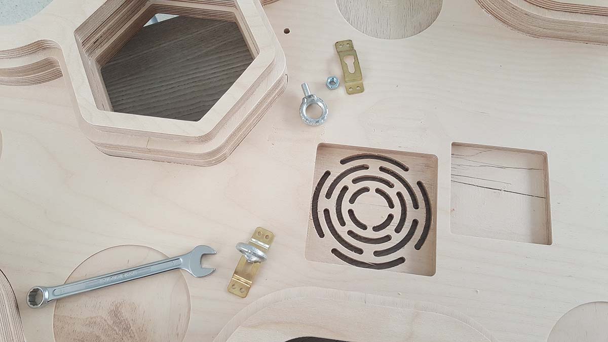
Assembling the Lighting
Assembling the water tubing
At this step I have faced a problem with the waterproofing of the pots, the water is leaking from the connection of the pot and the water tube and this is cause by the 3D printing process
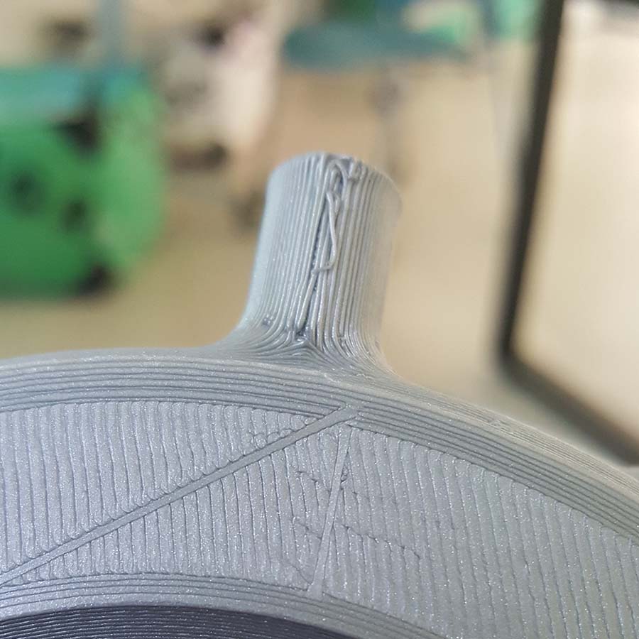
The problem was resolved by sanding the pot connection to remove the apparent filament and smooth it, then cover it with nail polish to close all the imperfection and make it smoother for the hose connection.
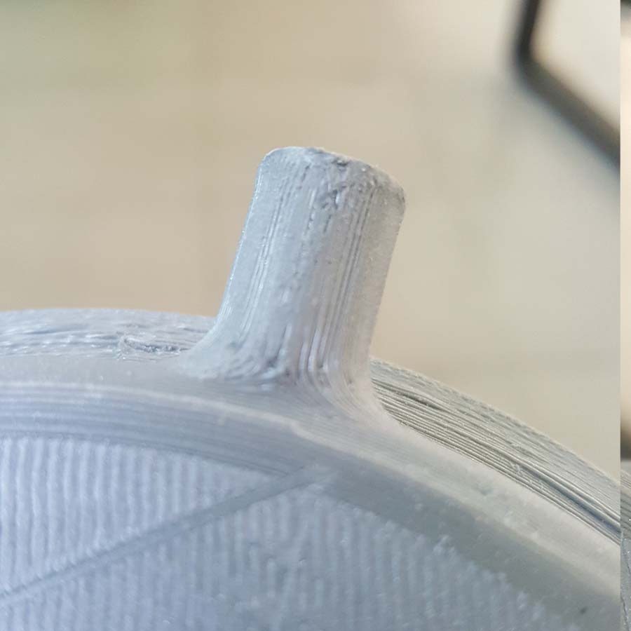
Then the connection is covered with a special hose tape and the hose is inserted and fixed with a metallic hose clamp.

And this is the result
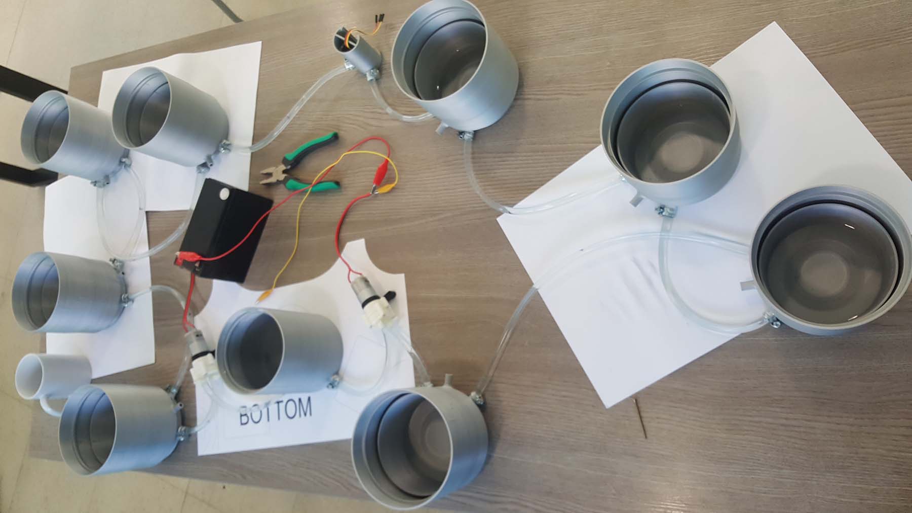
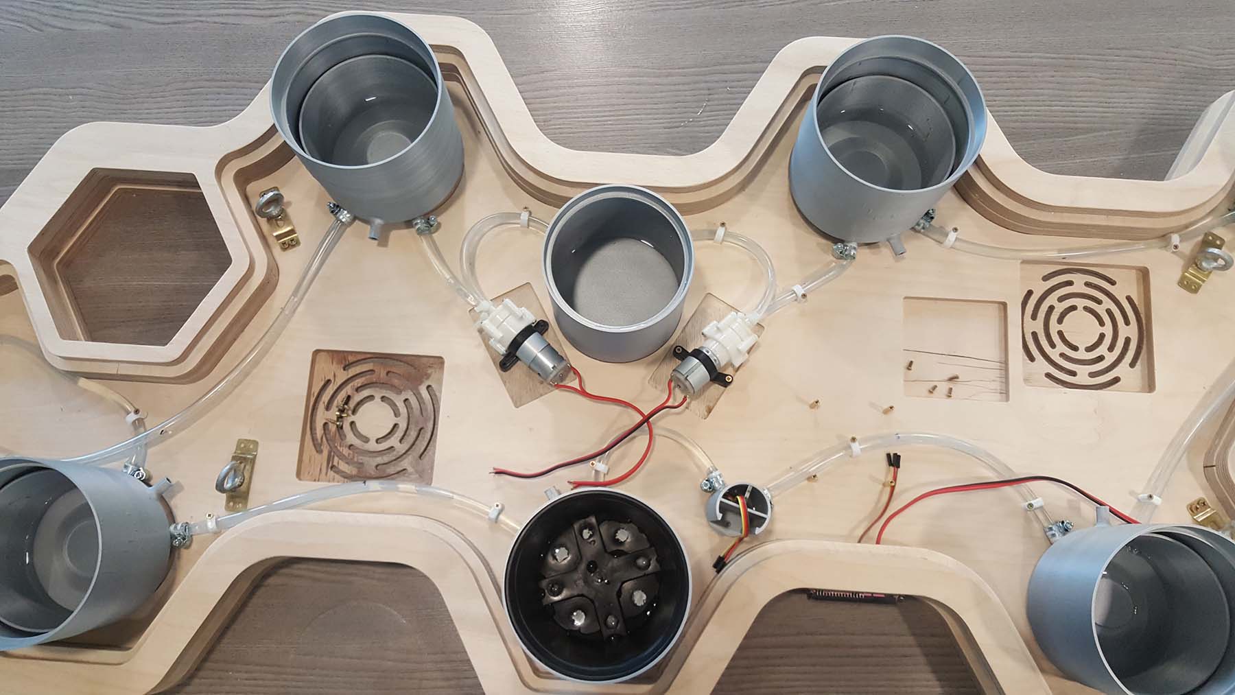
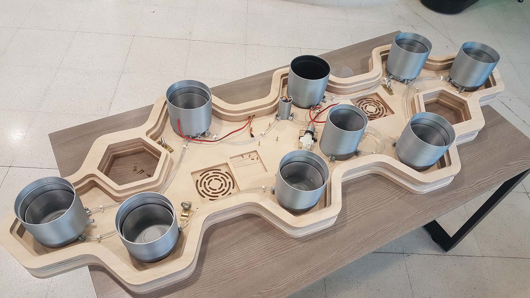
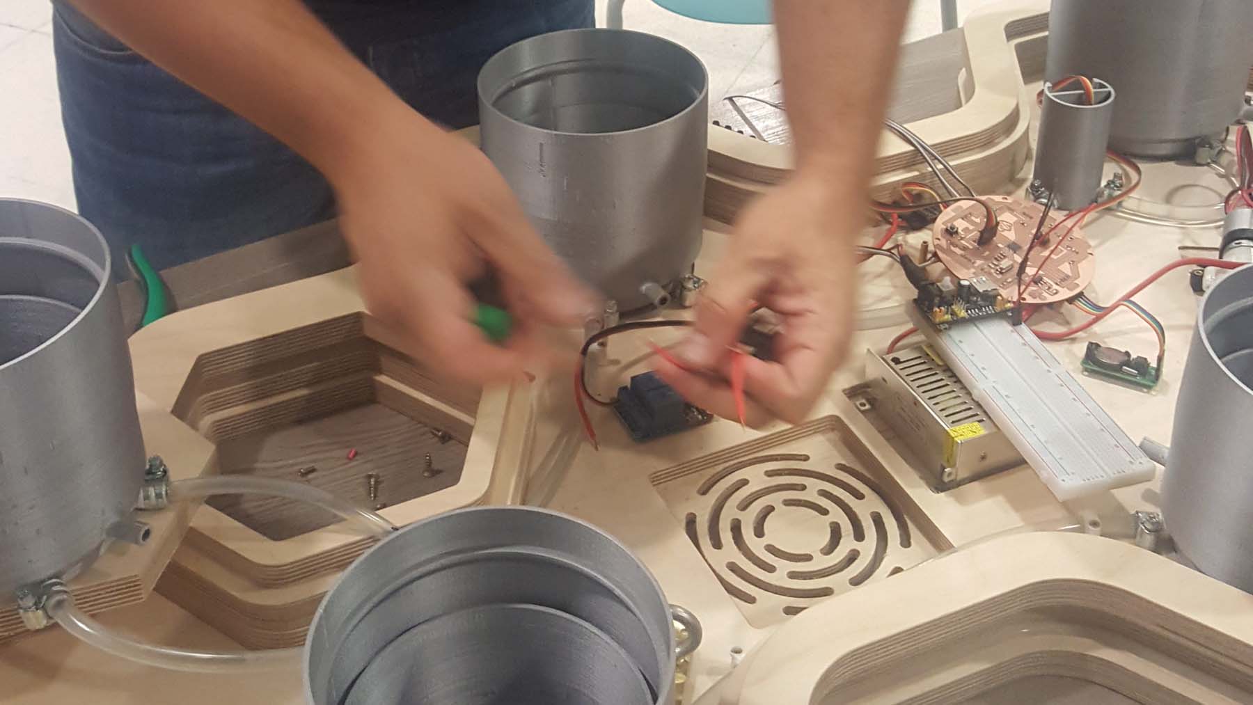
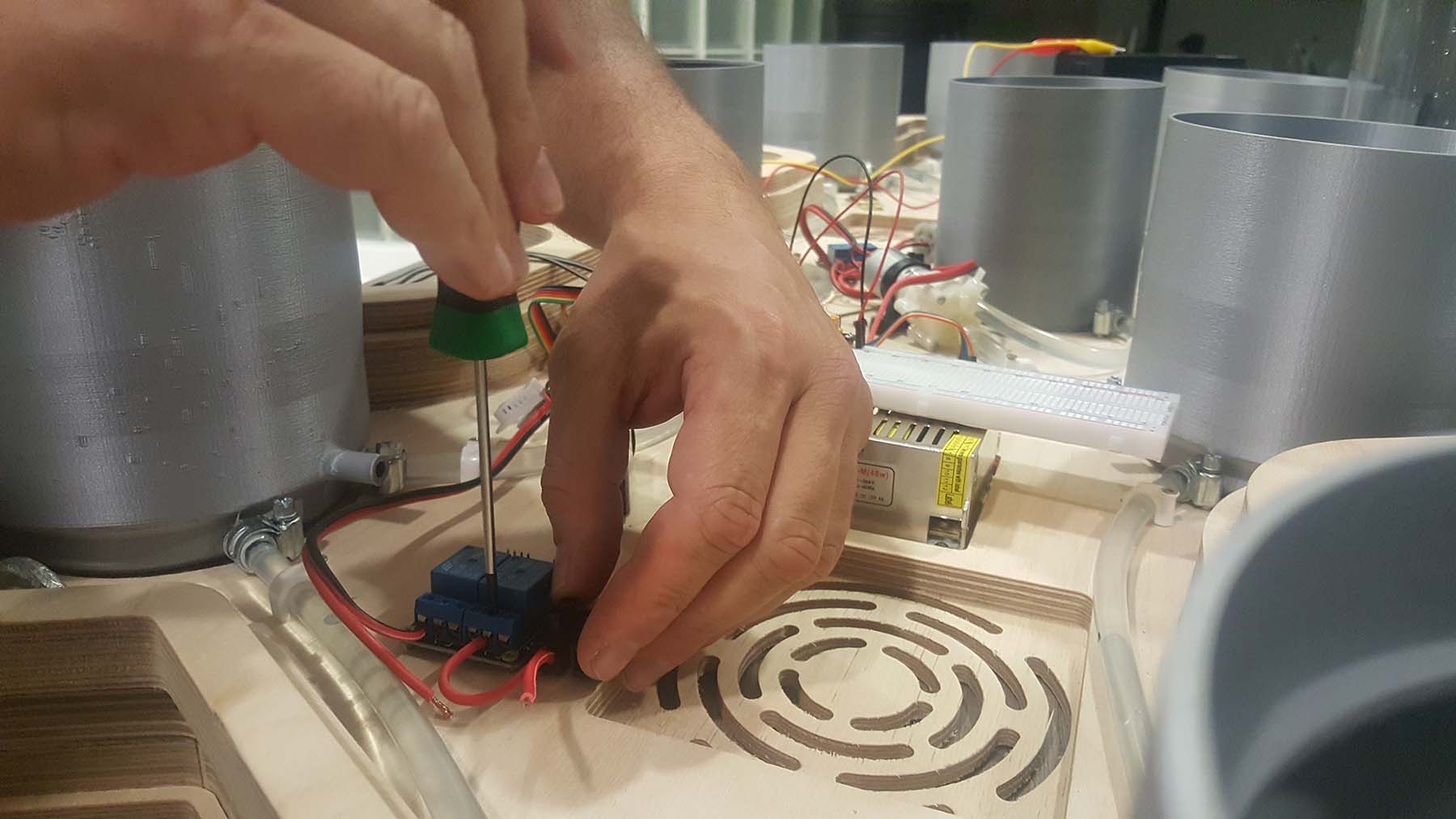
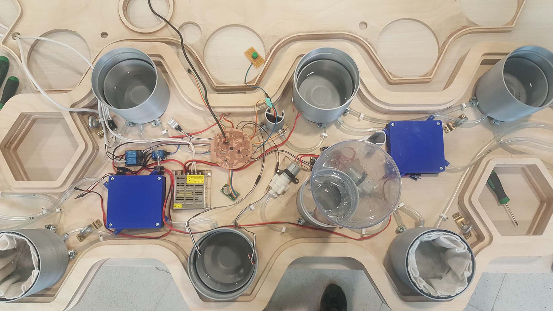
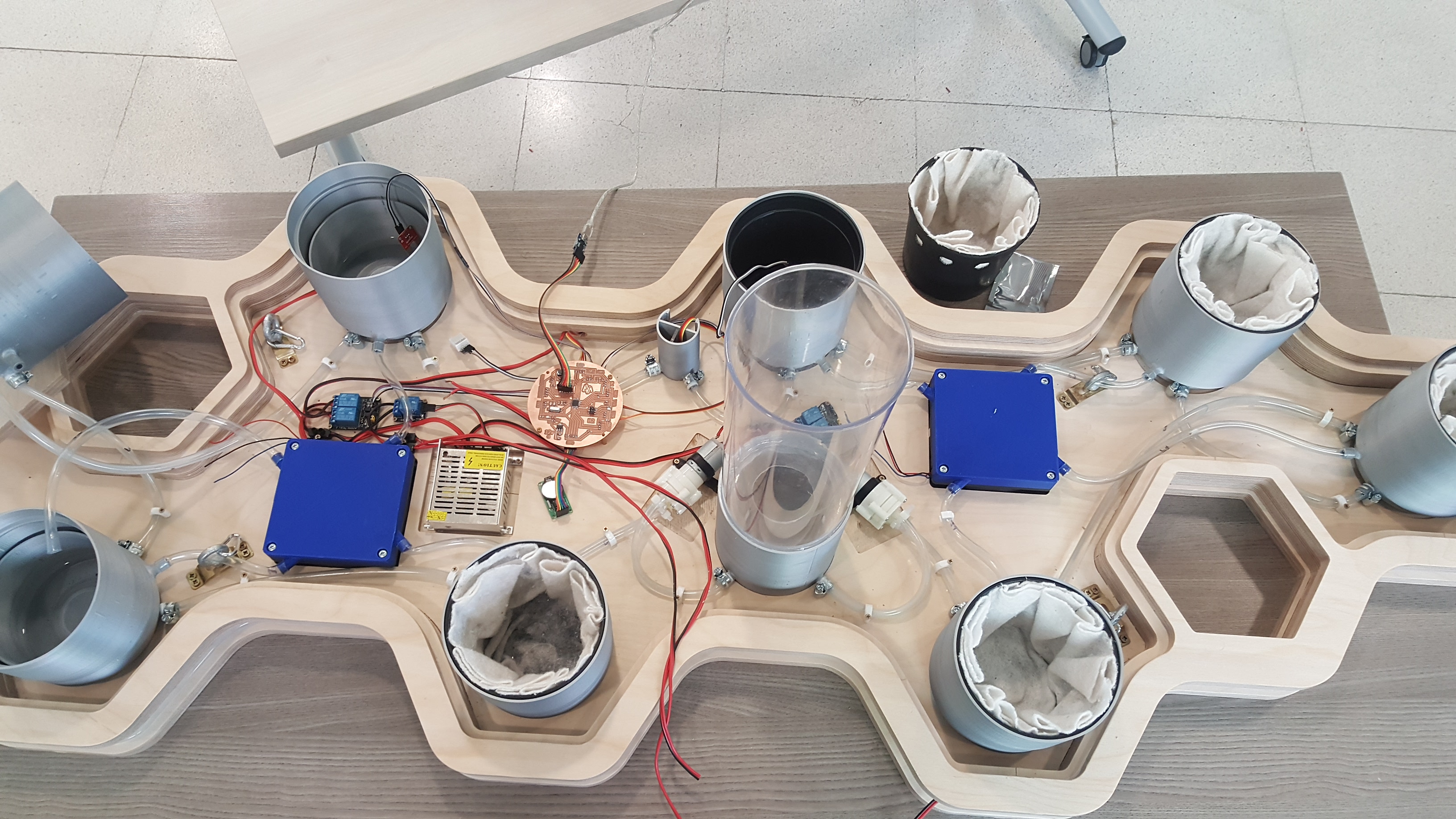
Assembling the electronic parts
Assembling the fans
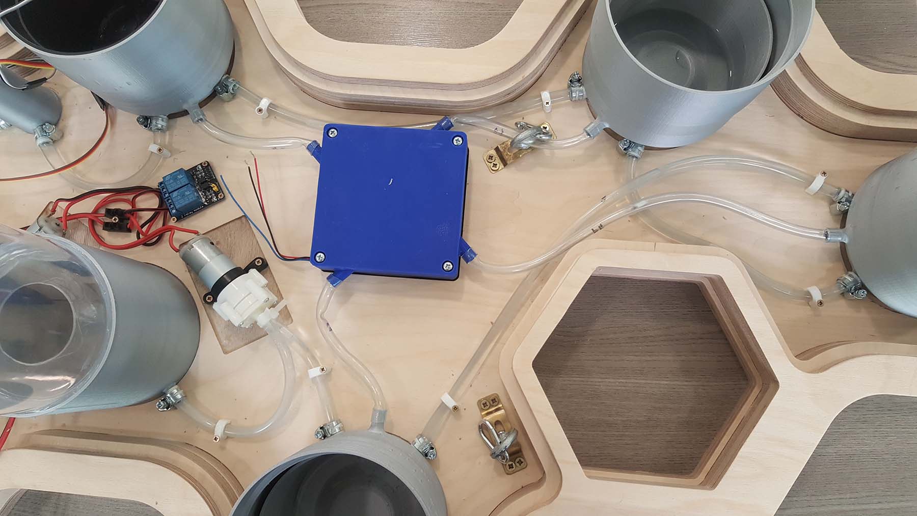
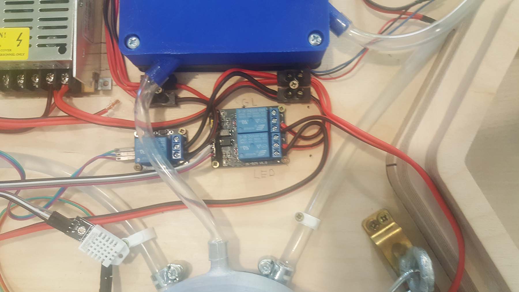
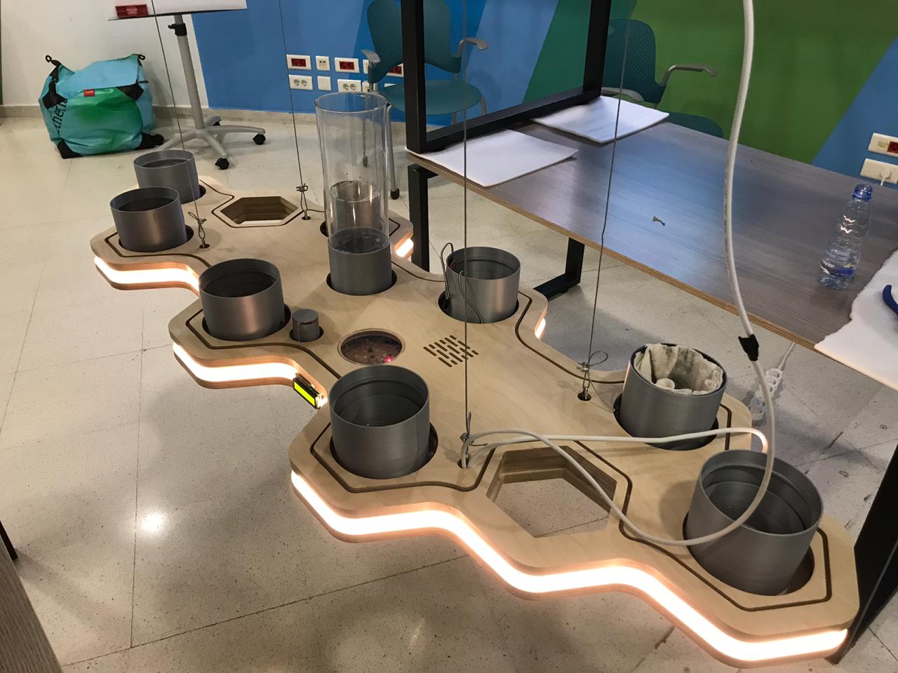
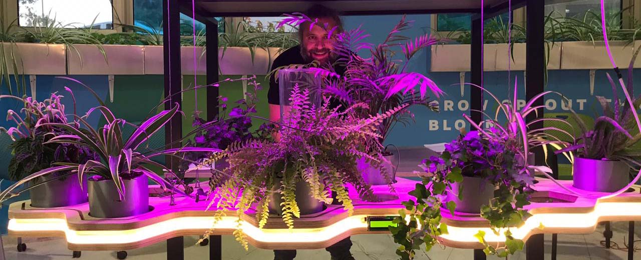
Assembly with all the components
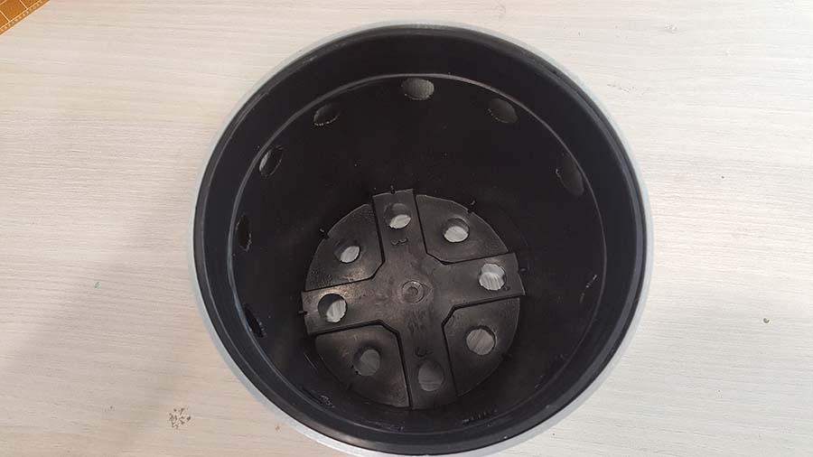
Installing the planting pots
The pot are perforated at the top-level to allow the ventilation
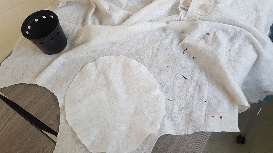
Geotextiles is used to prevent dirt from entering the watering system and act as filter for the soil and air circulation

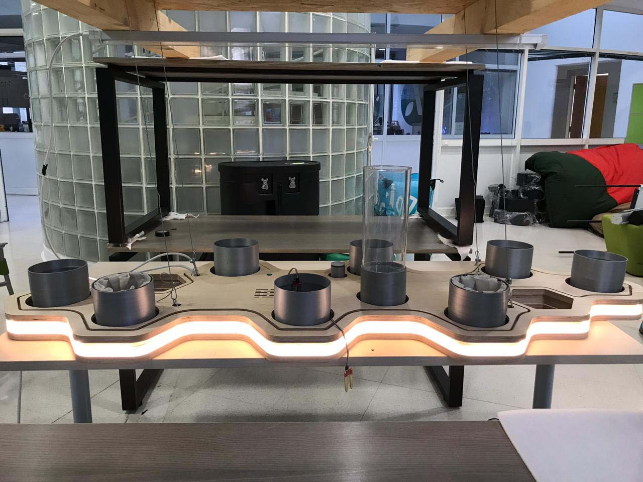
5-The Final result
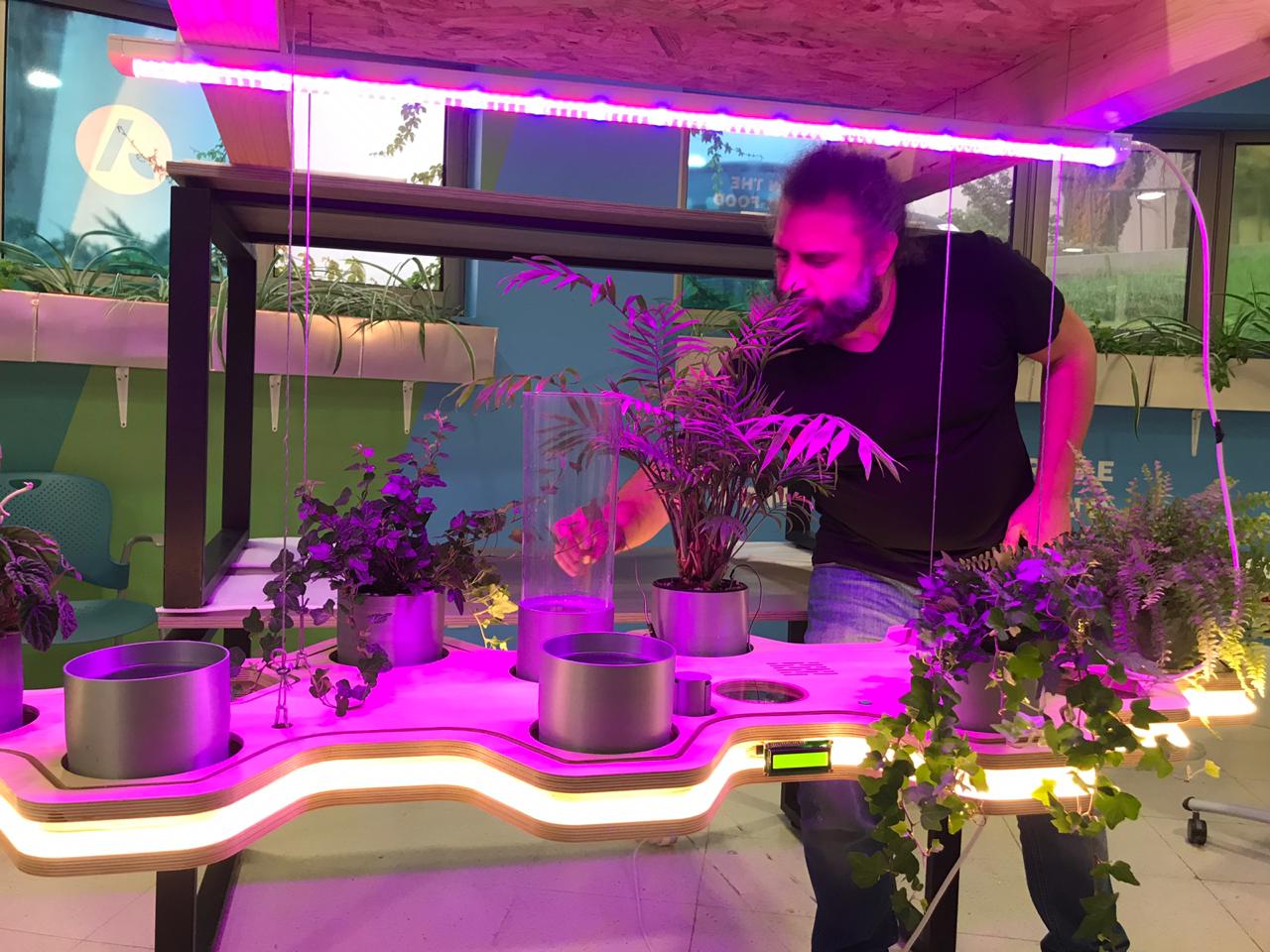
Summary
Now that I finished my final project using all the skills mentioned above and acheived all the targets I aimed for, below are some points that I should look into in the future:
- Take attention to the tube and pots waterproofing, the wood should be paint from inside with waterproofing material to avoid damaging it if anything goes wrong while testing.
- Use thicker water tubes to allow easier water movement between the pots.
- All the water tubes should be at the same level to avoid air pockets in the tube and retard water movement.
- The automation should be tested more and the sensors should be calibrated accordingly.
- The Plant should be watched over in the first period to see how they are reacting with the quantity of light and water received and the temperature / humidity detected . Then the program should be developed according to the data collected with the option of adding multiple scenarios.