Assignment
group assignment:
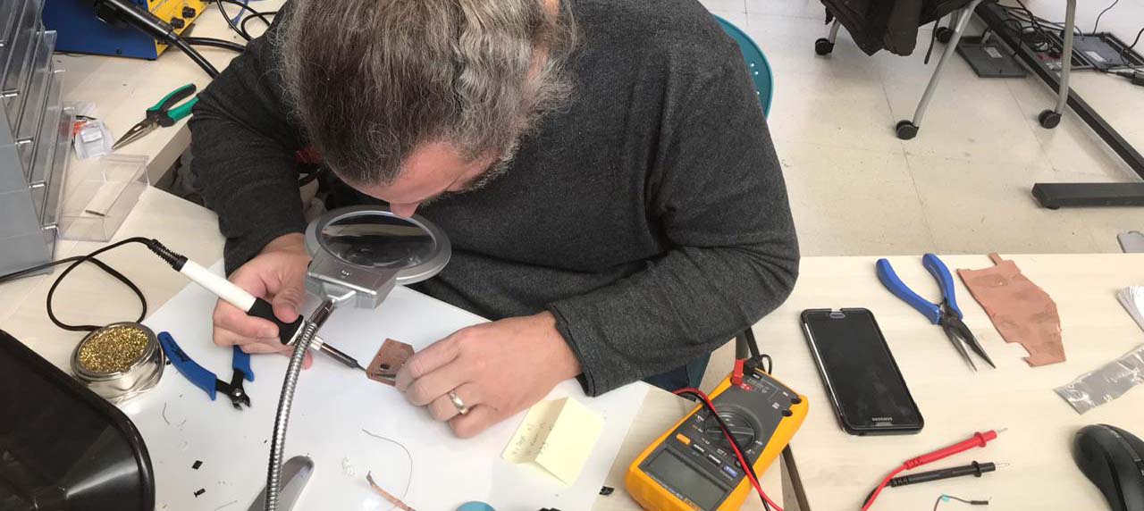
use the test equipment in your lab to observe the operation
of a microcontroller circuit board
individual assignment:
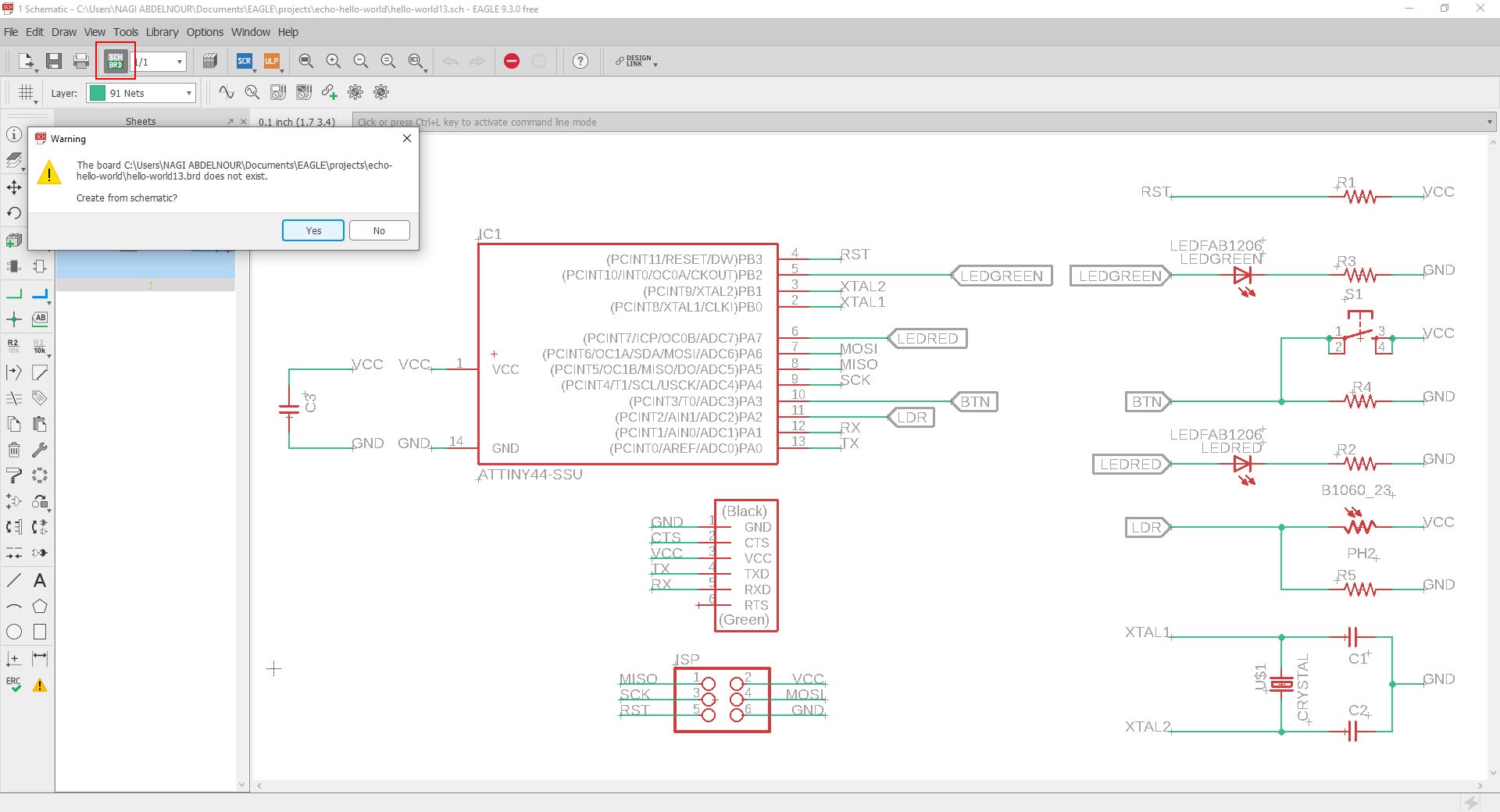
redraw the echo hello-world board,
add (at least) a button and LED (with current-limiting resistor)
check the design rules, make it, and test it
extra credit: simulate its operation
Individual Assignment
Redraw the echo hello-world board, add (at least) a button and LED (with current-limiting resistor) check the design rules, make it, and test it
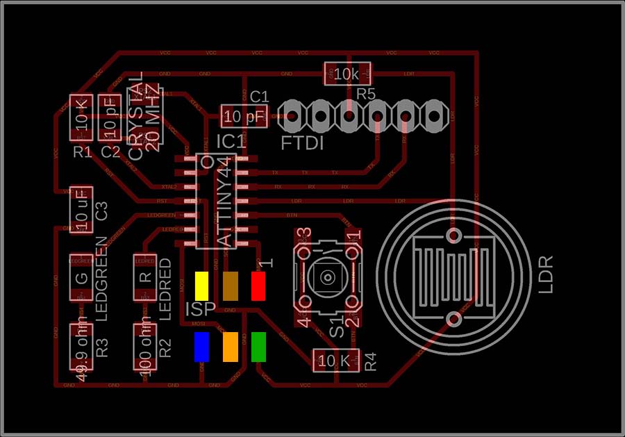
1-The Concept
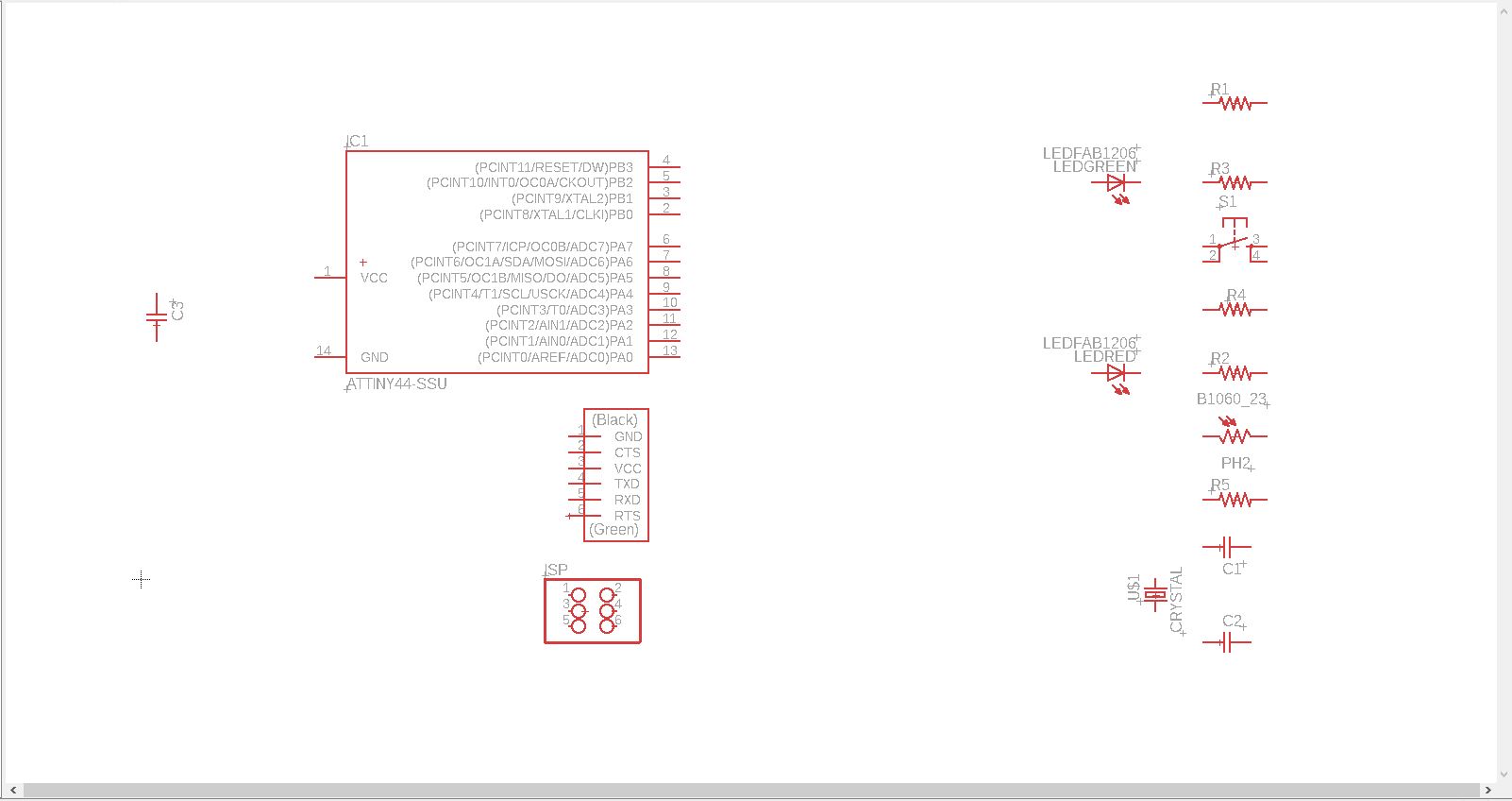
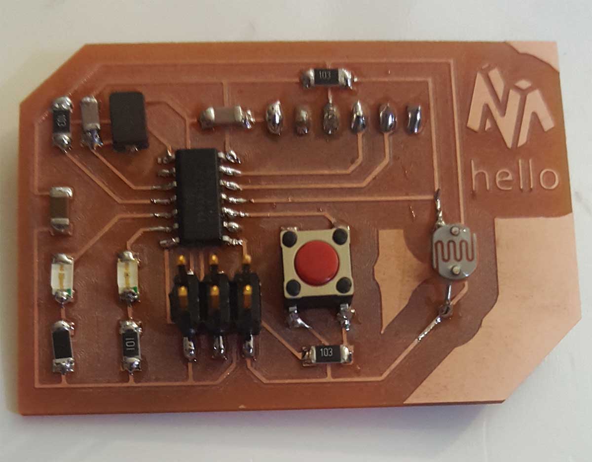
In this assignments I will make 'My' hello-world board where I will include 2 LED lights (red and green) a push button and a light sensor(LDR). The LED lights will be connected on the output pins and the push button & the light sensor will be connected on the input pins. After this I can do the scenario I want in the programing part.
And all this will be based on the original hello-world board below:
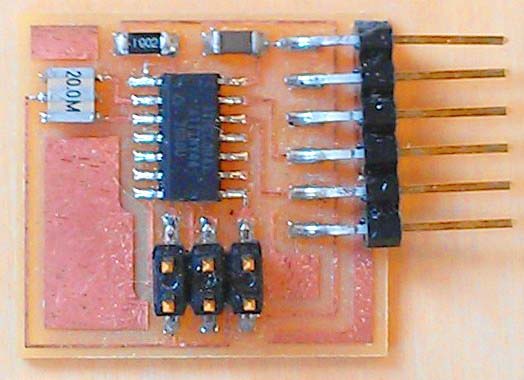
Below is the list of the Original hello-world components:
- ATtiny44 x 1
- Resonator 20MHZ x 1
- Resistor 10K x 1
- Capacitor 10uf x 1
- ISP header x 1
- FTDI header x1
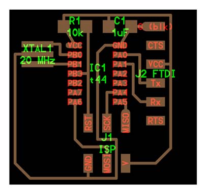
In My hello-world board we will not use the Resonator and we will replace it with a Cristal and 2 Capacitors.I will add 2 LED (1 green and one red) with 2 resistors for each , I will also add a Push Button with a resistor and finally a light detector with a resistor.
So the list of components will be:
- ATtiny44 x 1
- Cristal 20MHZ x 1
- Capacitor 10pf x 2
- Resistor 10 K ohm x 1
- Capacitor 10uf x 1
- ISP header x 1
- FTDI header x1
- LED green x 1
- Resistor 49.9 ohm x 1 (for green Led)
- LED red x 1
- Resistor 100 ohm x 1 (for red Led)
- Push Button x 1
- Resistor 10 Kohm x 1 (for Push Button)
- LDR (light detector)
- Resistor 10 Kohm x 1 (for LDR)
2-The Sketch
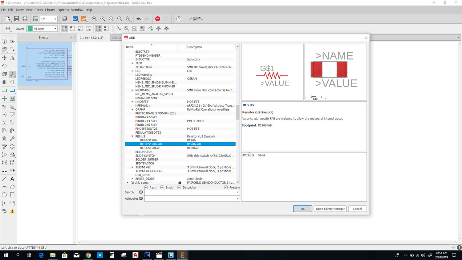
I will use EAGLE software to sketch the board.
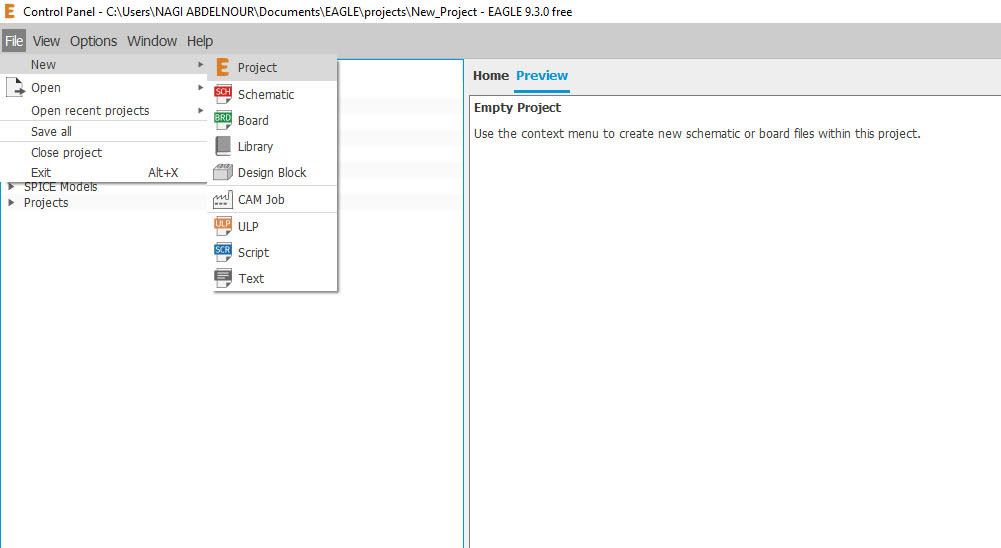
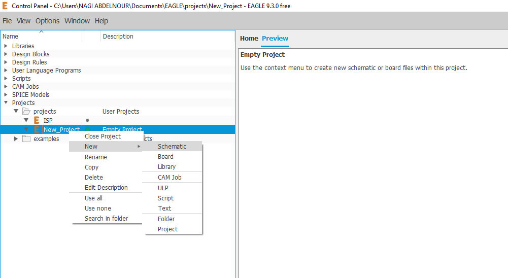
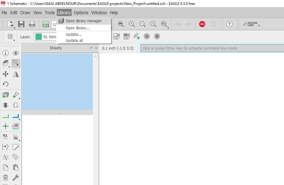
First I will open EAGLE , start a new Project and create a new Schematic.
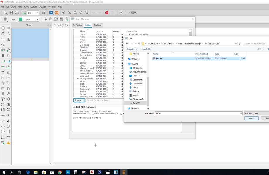
Then I will need to add the fab library to EAGLE. For that I click on library / open library manager/ In Use / Browse for the fab.lbr file.
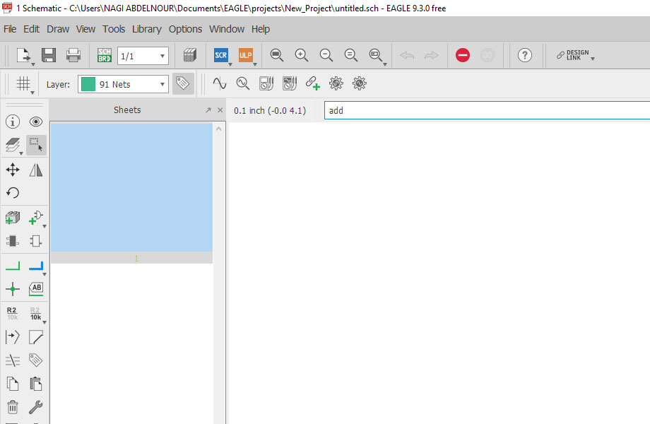
Now I can start adding the components to my schematic. On the Command line I will type 'add' and start searching for my components in the added library.
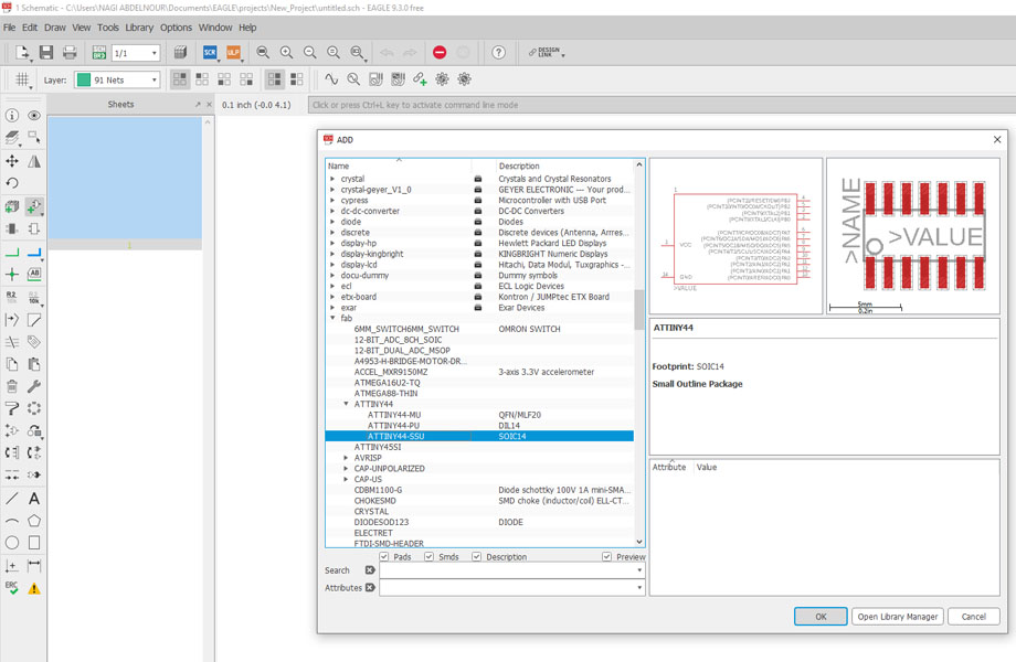
After adding the ATtiny44 I will add the resistor , the capacitor and the header
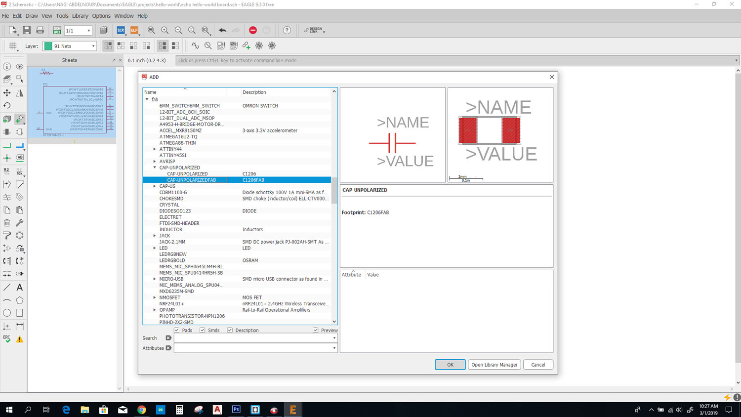
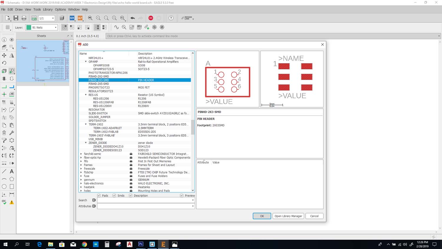
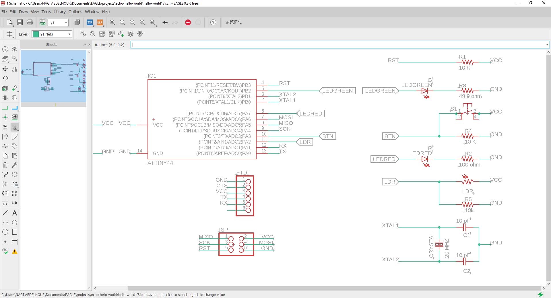
And after adding all the needed list of components, I need to connect them to each others.
For that I need to place a net and a tag at each net, so that we know which wire is connected to what part.
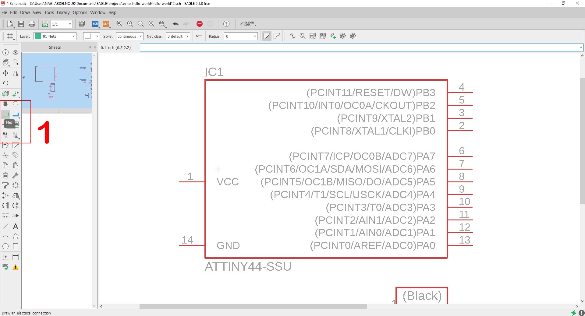
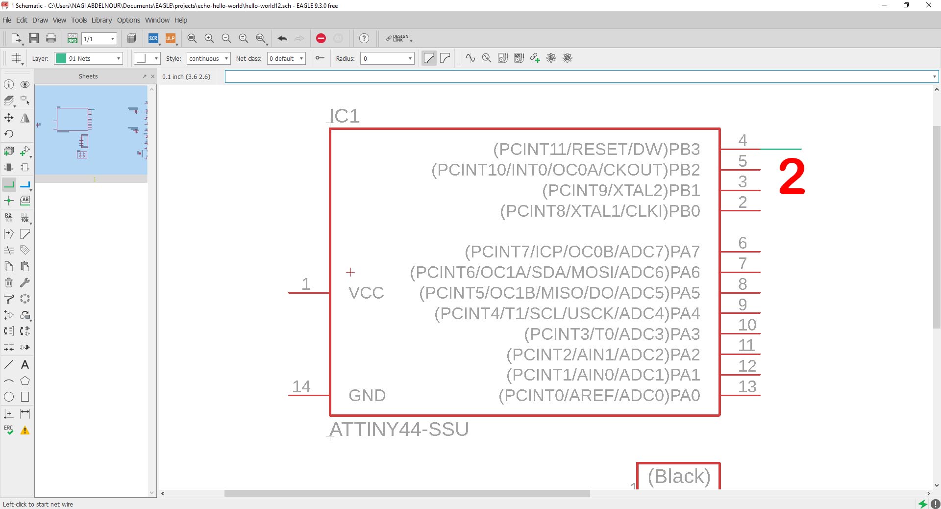
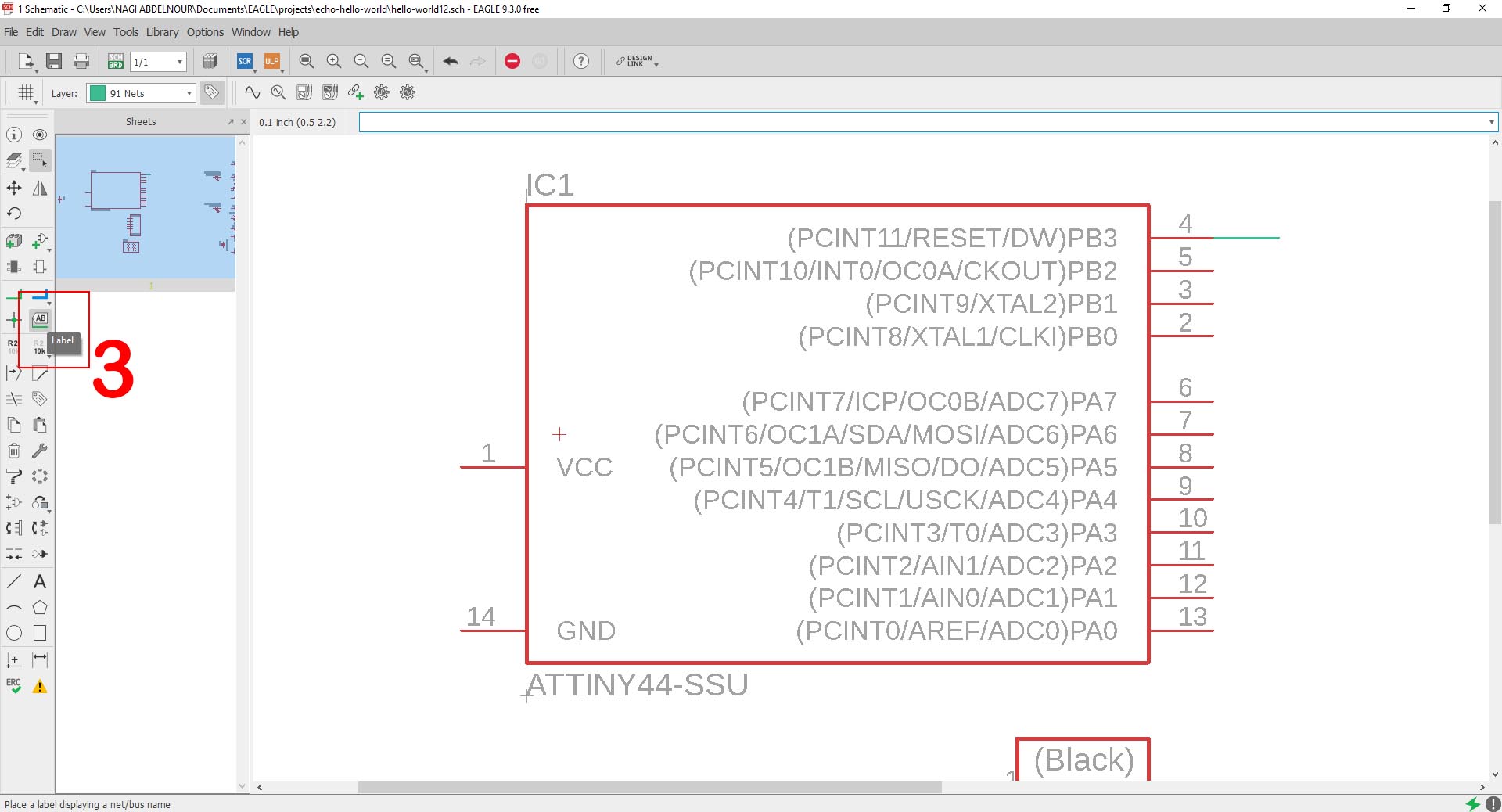
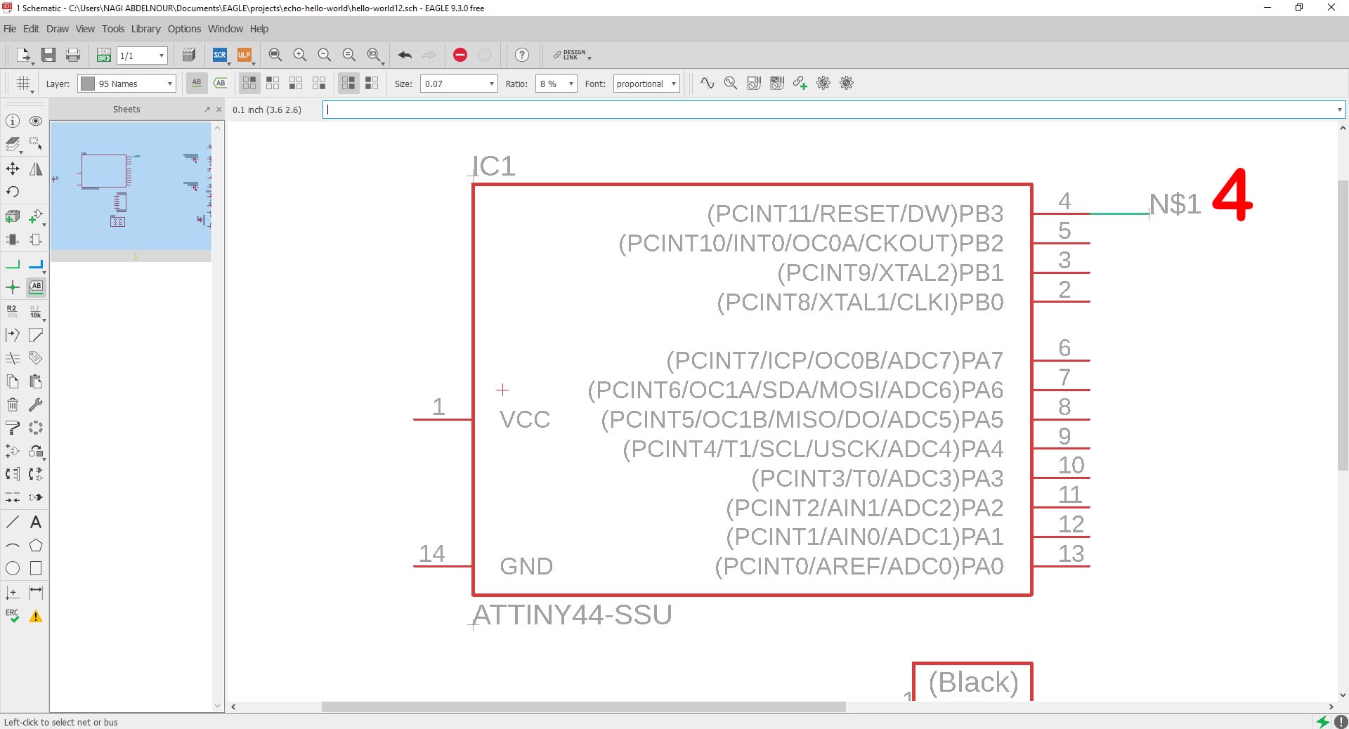
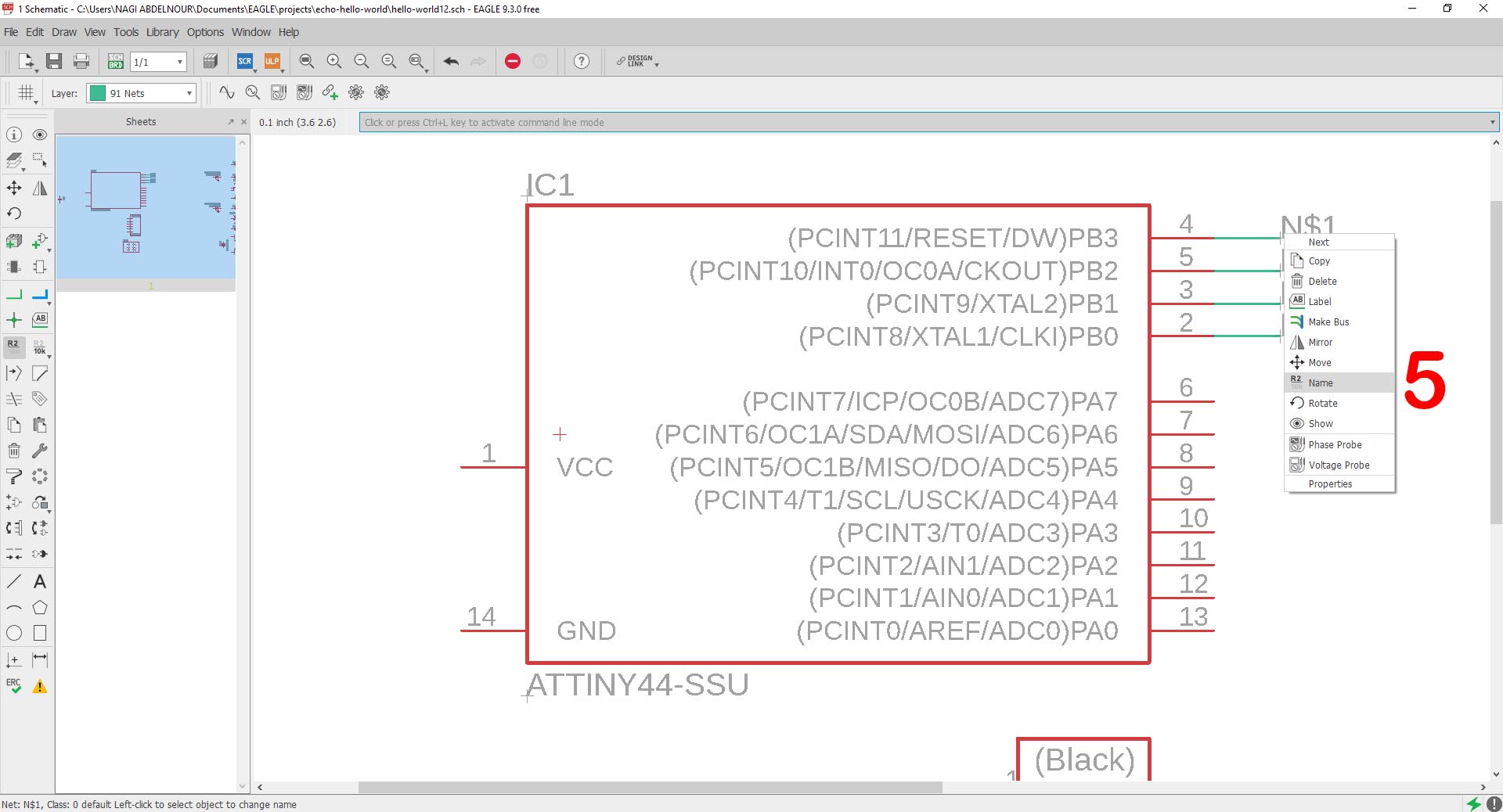
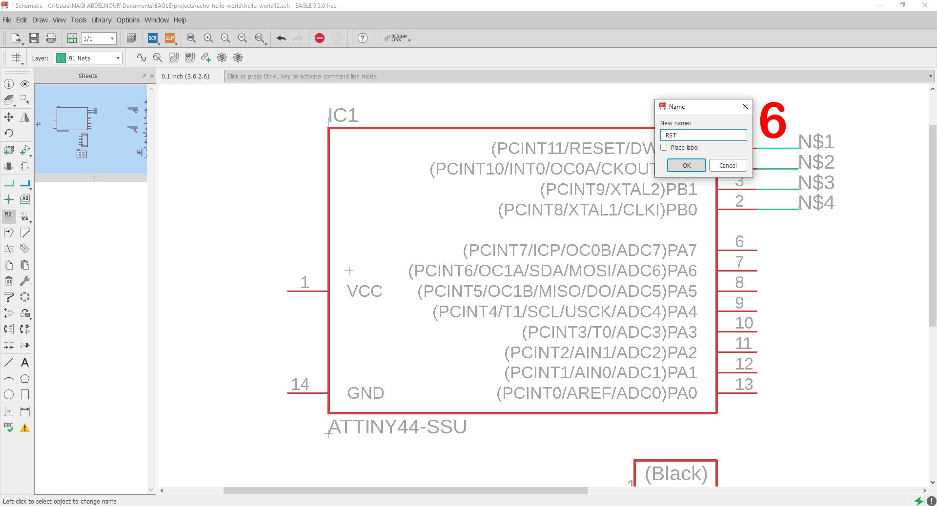
I will repeat this for all the connections and enter the values for the components.
The components calculation and the links explanation.
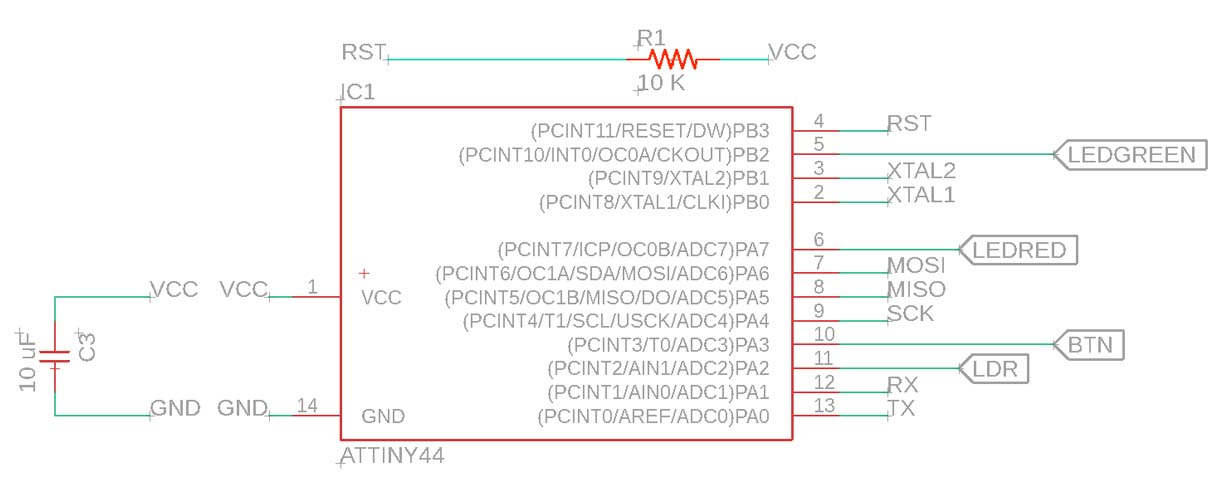
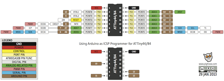
Attiny44 MCU
The MCU (MicroController Unit) Attiny44(in our case) has a default pin configurations as per the data sheet
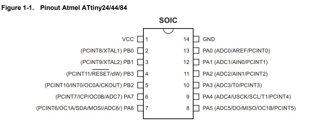
What we can retain from all this is the following:
- Operating Voltage Range: 2.7 -5.5V
- Internal Clock of 8 Mhz
- Pin 1,2,3,4,7,8,9,12,13,14 are default connections
- Pin 5 for is for output
- Pin 6,10,11 are for output an input
In my board, Pin 5 will be for the green LED(output) , Pin 6 for the red LED(output), Pin 10 for the button(input) and Pin 11 for th LDR(input)
The Reset button should be connected to VCC (high) with a resistor 10k(according to the original design) and we should add a Capacitor 10uf(according to the original design) between the VCC and the GND to avoid any noise interferences.
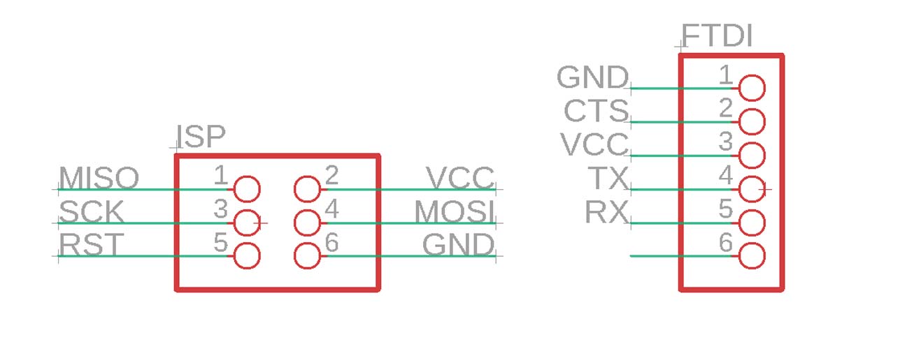
ISP and FTDI connection
The ISP connection is to program the board and the FTDI connection is to link it to the PC serial port. And below are the default connections:
The Cristal
To extend the speed of the MCU, an external clock (timing crystal) can be added on pin 2 & 3 (XTAL1 & XTAL2).
The internal operational speed of the ATtiny44 MCU can get up to 8 MHz. So by adding a Crystal of 20 Mhz we extend the speed by 2.5 times.
Usually it may require some capacitance to make it operate. This can be found in the datasheet of the crystal. It is suggested to use a 8pF capacitor.
And below are the default connections:
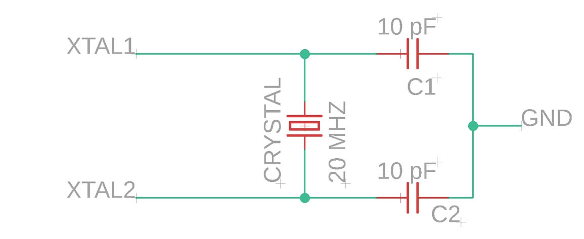
The Cristal data sheet
We will use 2 Capacitors of 10pF (availble instead of 8pf) for the Cristal
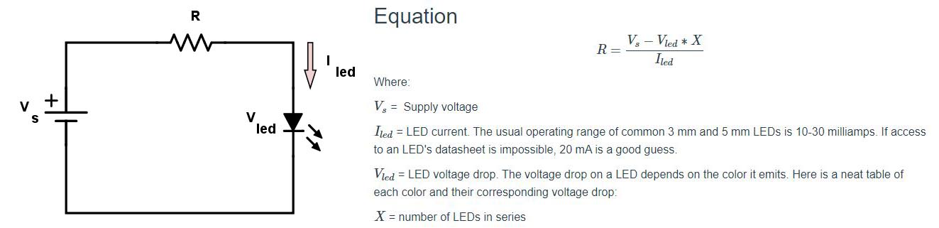
The LED
The LED requires a current limiting resistor. The resistor is calculated as below:
The Green LED data sheet
The Red LED data sheet
The Resistor for the Green LED will be = 5-3.8/0.03 = 40 Ohm , so we will use the available 49.9 Ohm
The Resistor for the Red LED will be = 5-2.4/0.03 = 86.6 Ohm , so we will use the available 100 Ohm
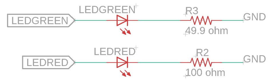
And remember that the LED are diodes and have polarity: the line and the dot should be towards the ground side.

The push button
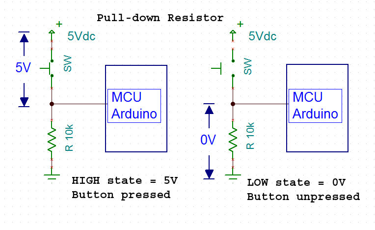
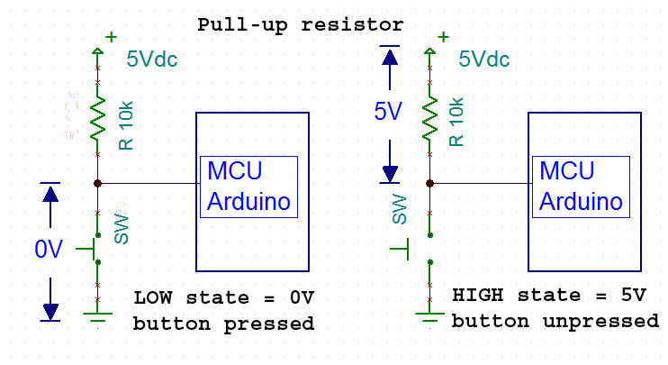
Pulling high/low with anchor. In order to ensure that the pin on the microprocessor sees a distinct HI and LO, both states of the switch have to be connected to the circuit. If the switch were only connected to Vcc to make the HI, then when the switch is open, the pin would "float".
By connecting the pin to GND through a resistor, the voltage is held low when the switch is open. When the switch is closed, then the current flows through from Vcc, and the voltage rises to the HI state.
Example:
The push button data sheet
In my board it is a pull-down resistor:
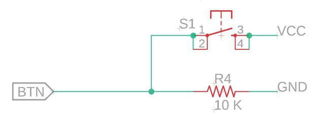
The Resistor for the push button will be 10k.
The LDR
An LDR is a component that has a (variable) resistance that changes with the light intensity that falls upon it.
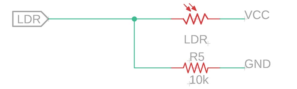
The LDR data sheet
The LDR has a high resistance of 40 k in the dark and 2 k in the light the average of the LDR is around 20 k so a Resistor of 10k will do the job.
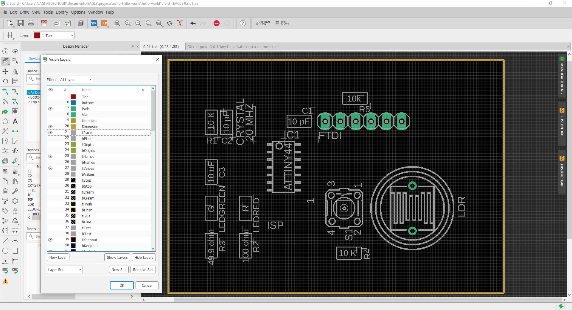
3-The Board
First I will create the board by clicking on generate board.
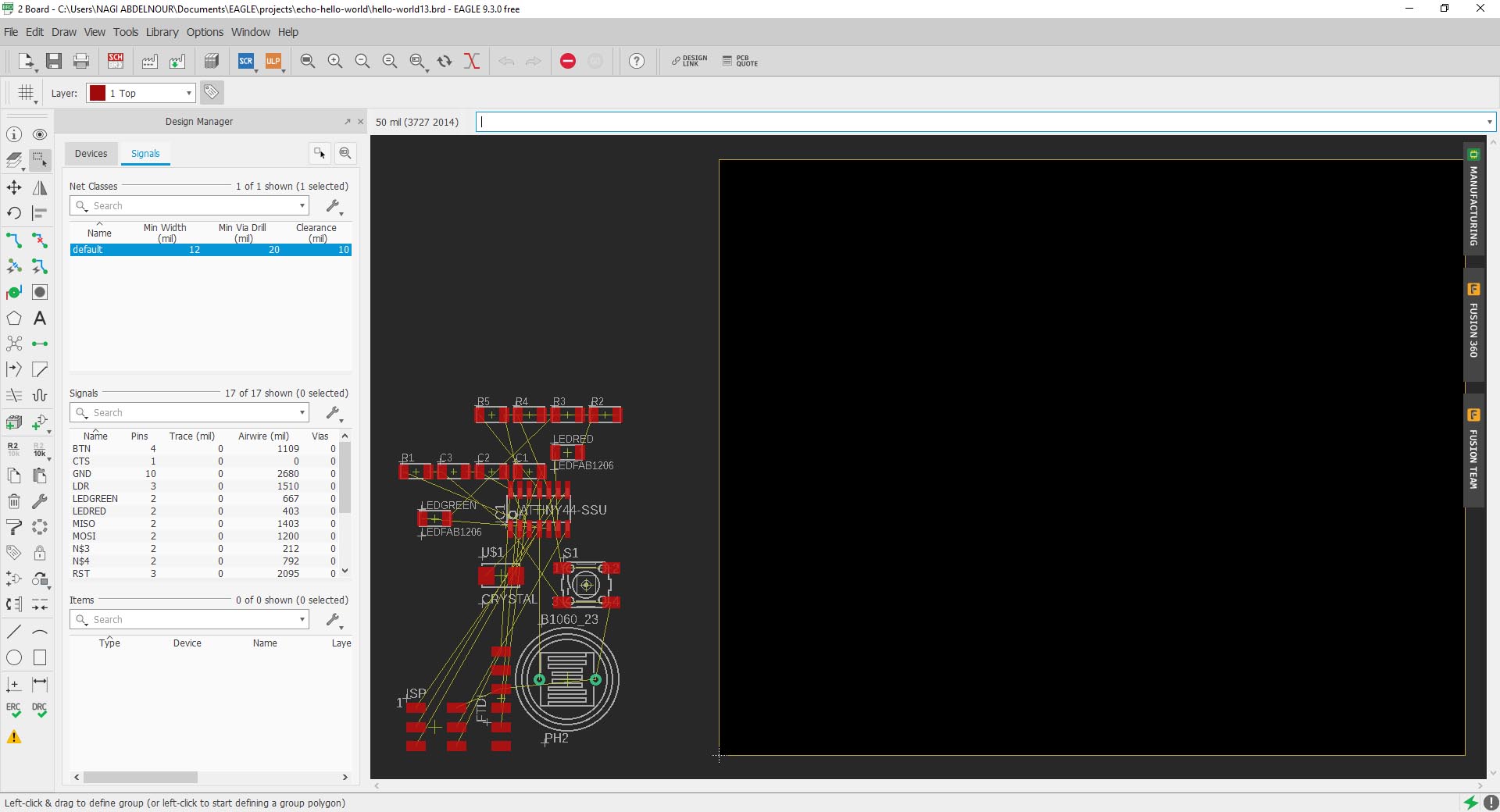
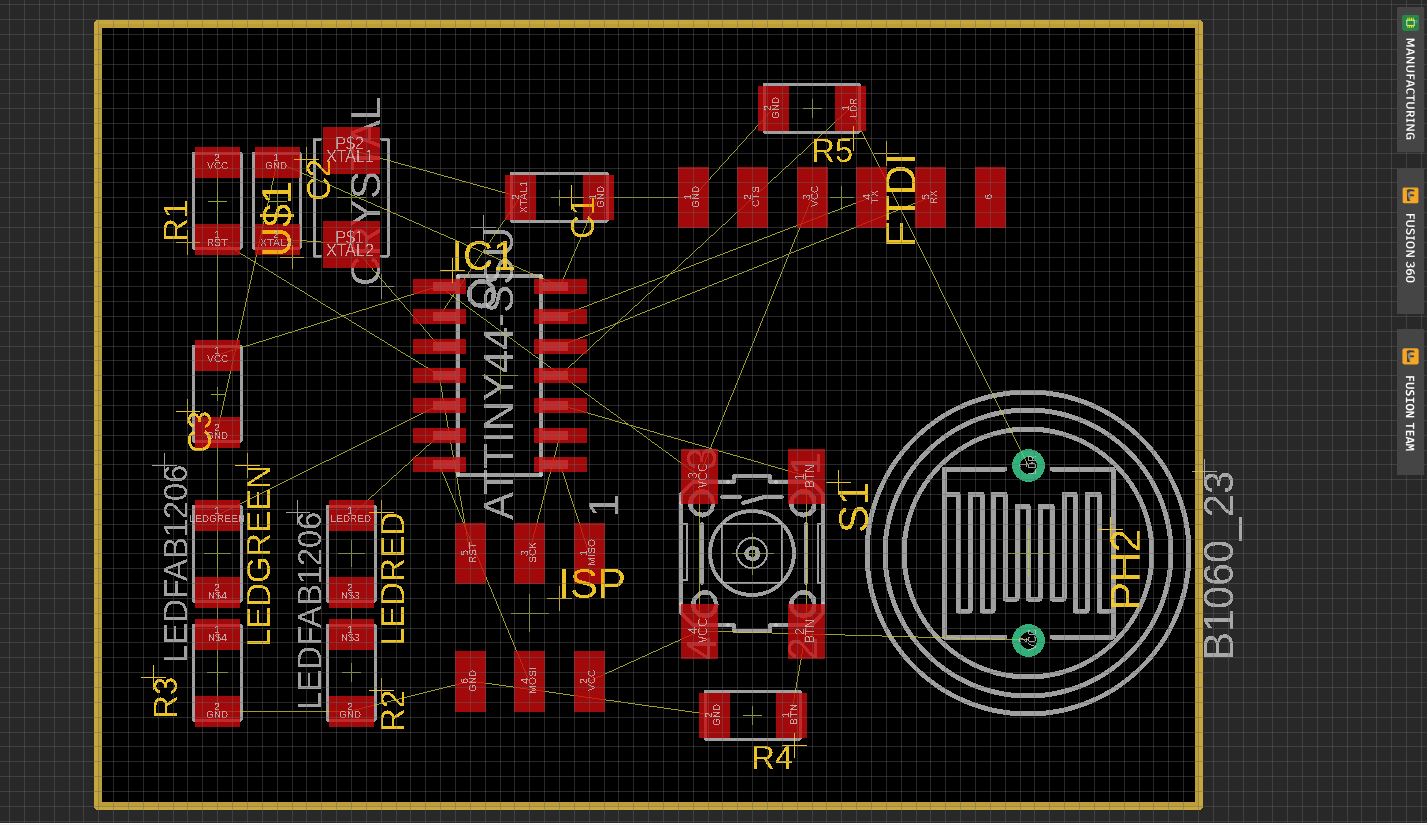
Now I will start placing the components on the board .
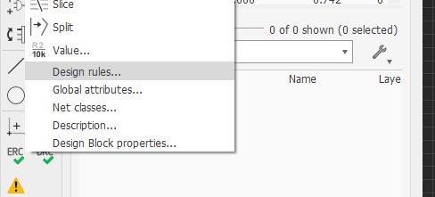
Then I will adjust the design rules before routing. For that I open Design rules from the toolbar => Edit => Design rules
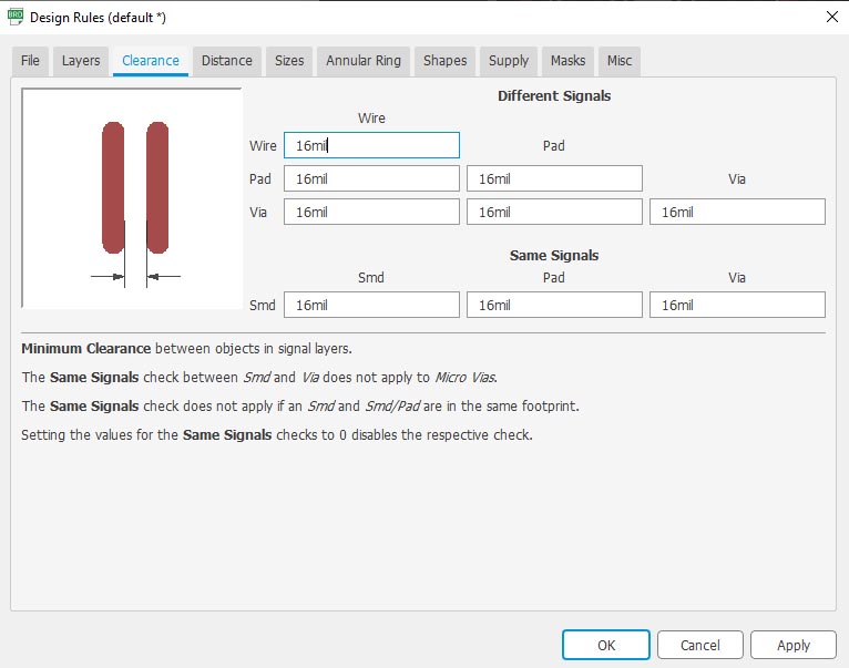
Adjust the Clearance to 16mil
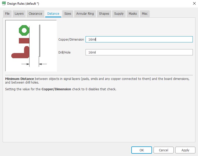
Adjust the Distance to 16mil
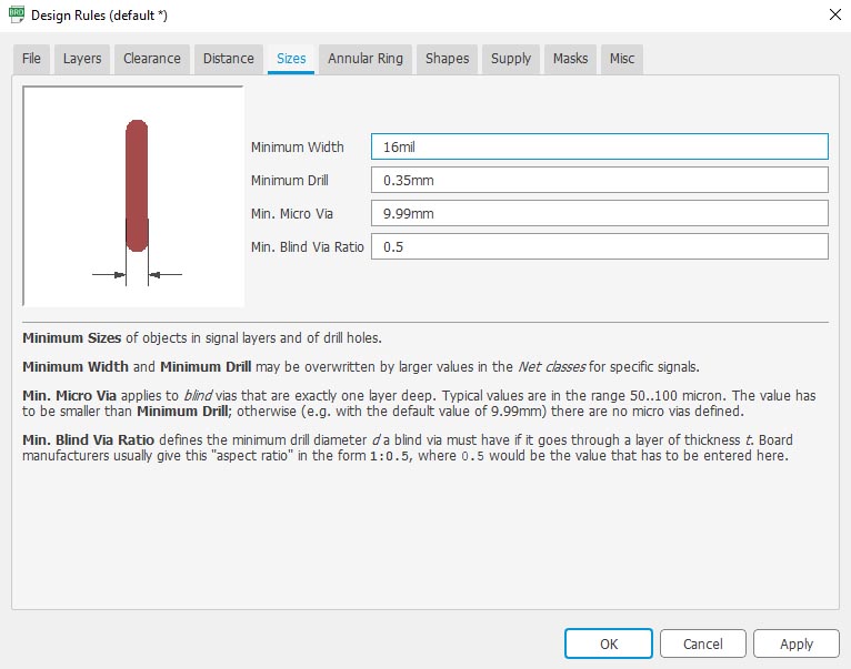
Adjust the Size to 16mil
After that I will start using the Route command and adjusted the Grid to have more precision.
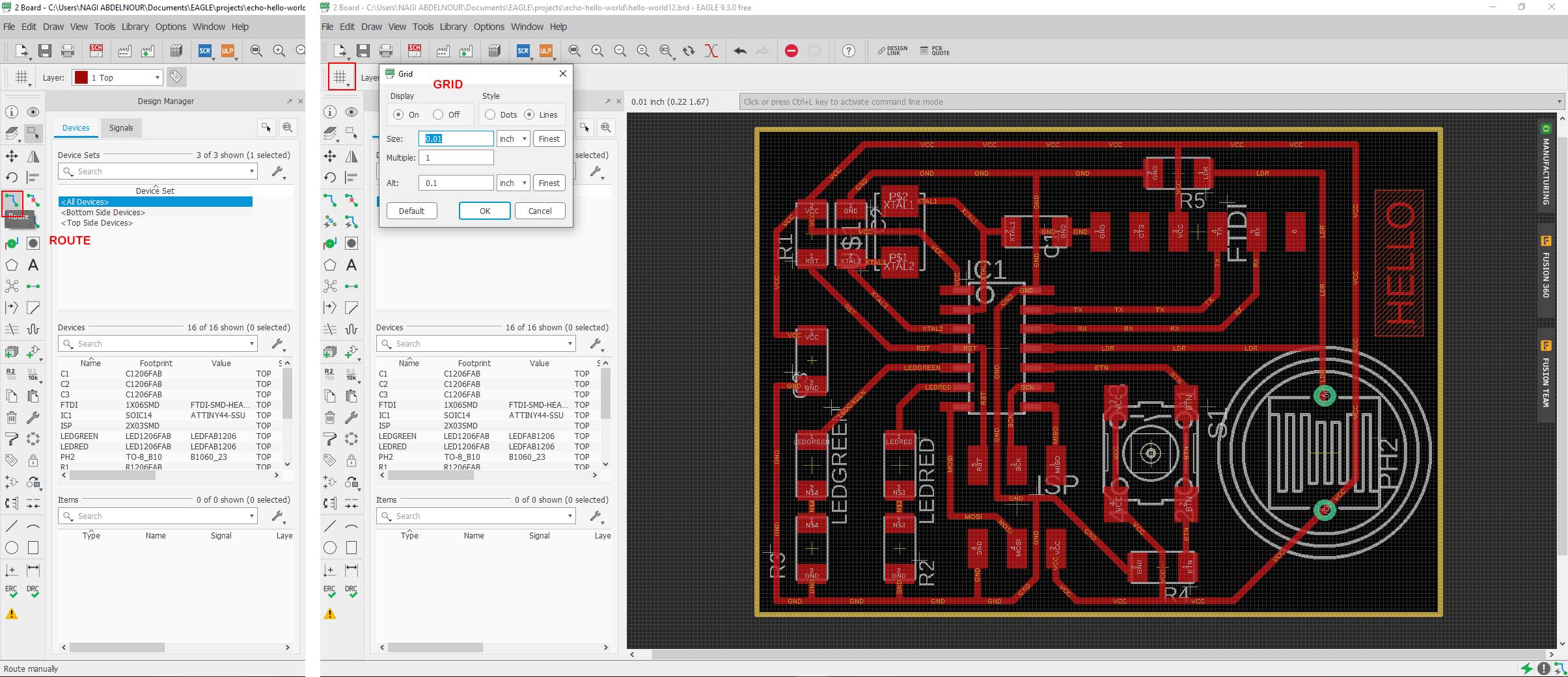
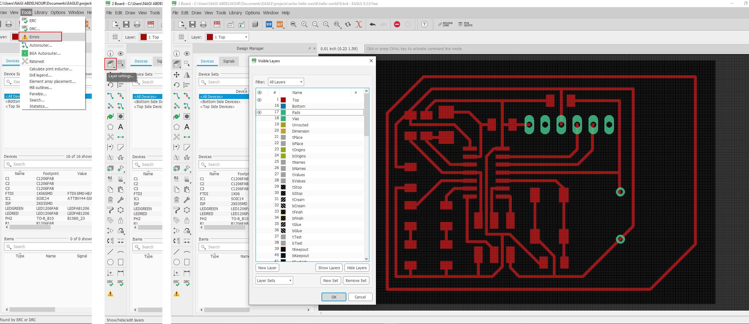
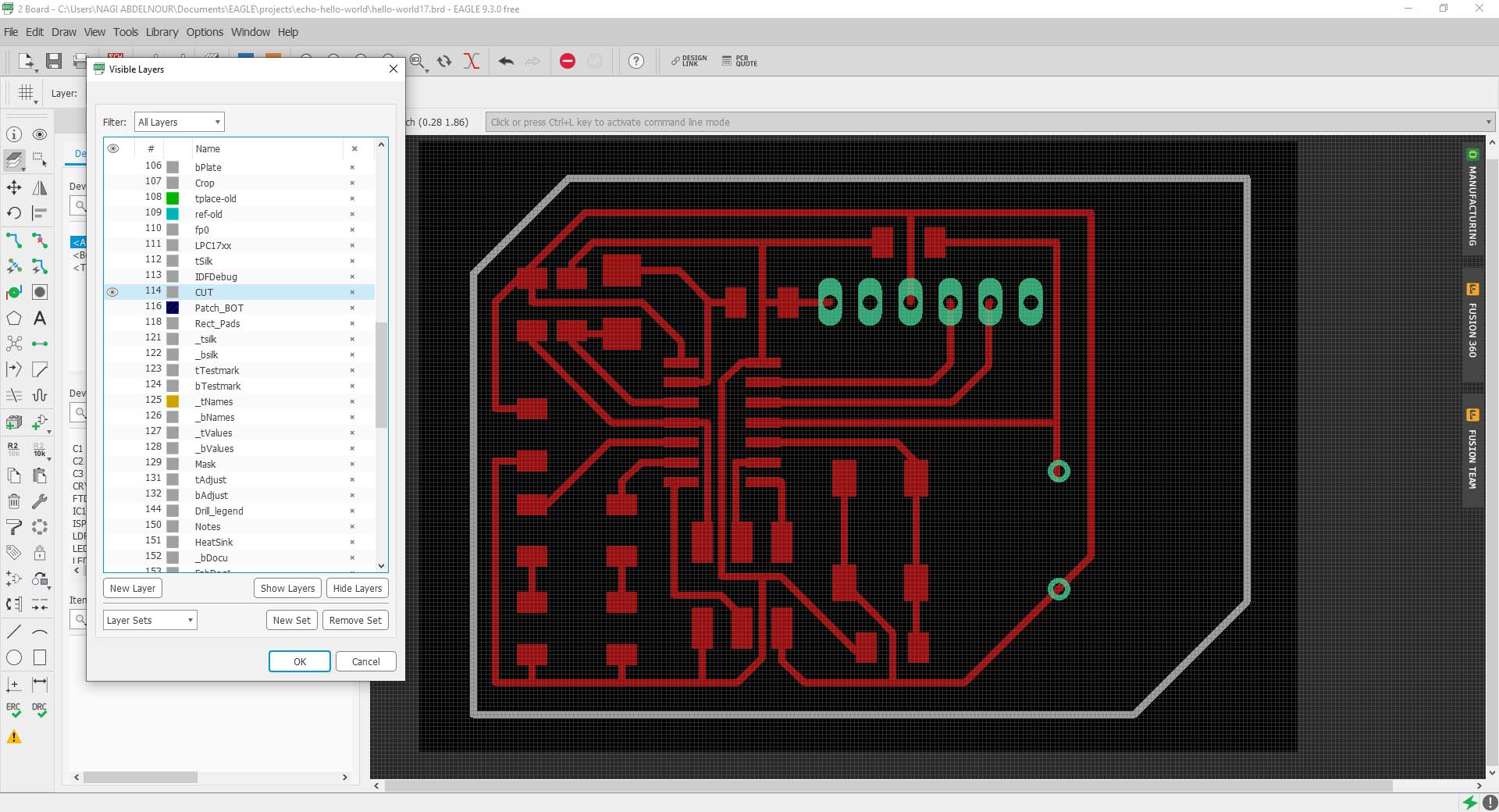
And finally I will check for errors then go to Layers dialog and turn off all the layers except the Top and the Pads(this is for the inner traces and cutout).
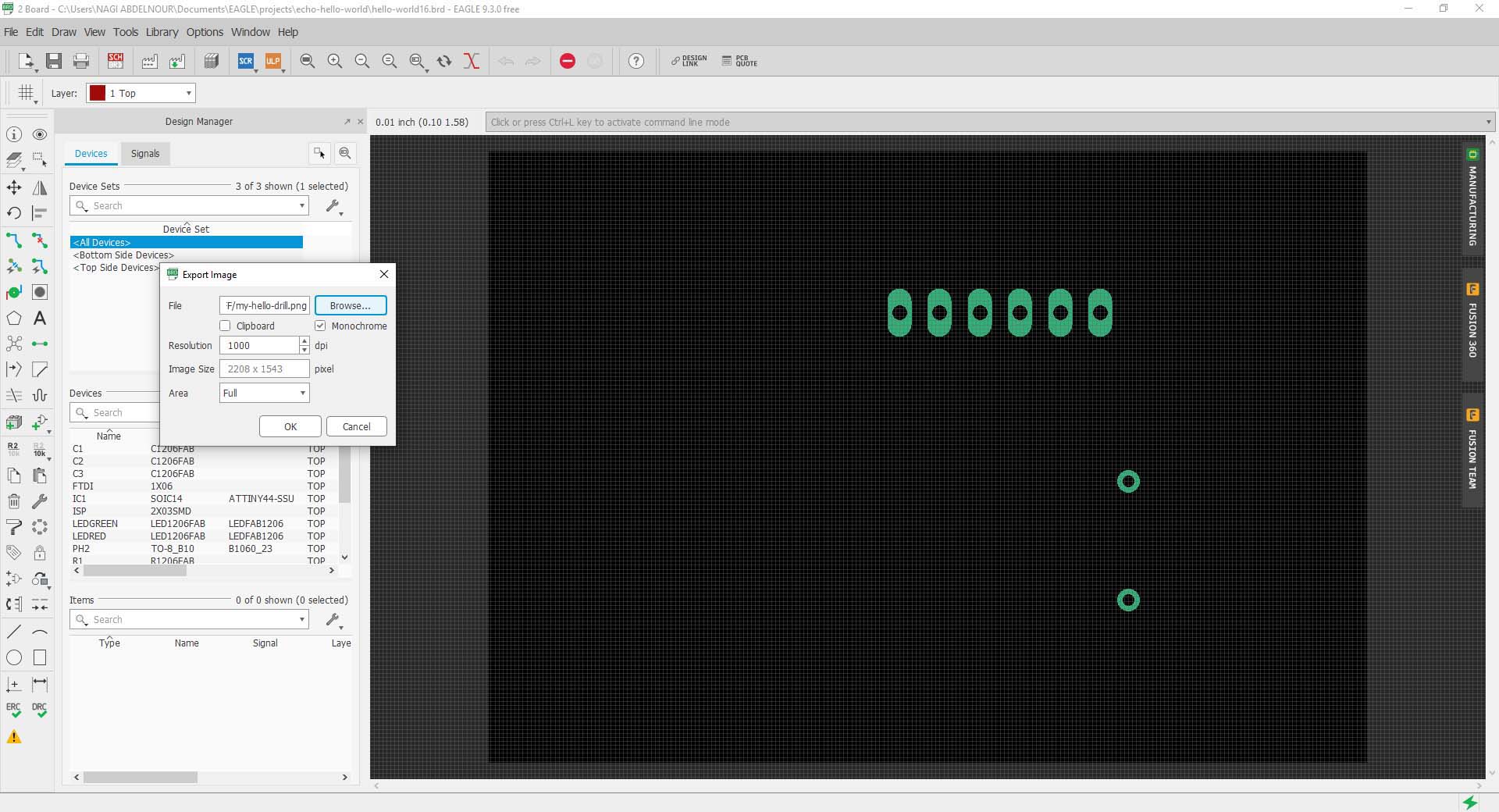
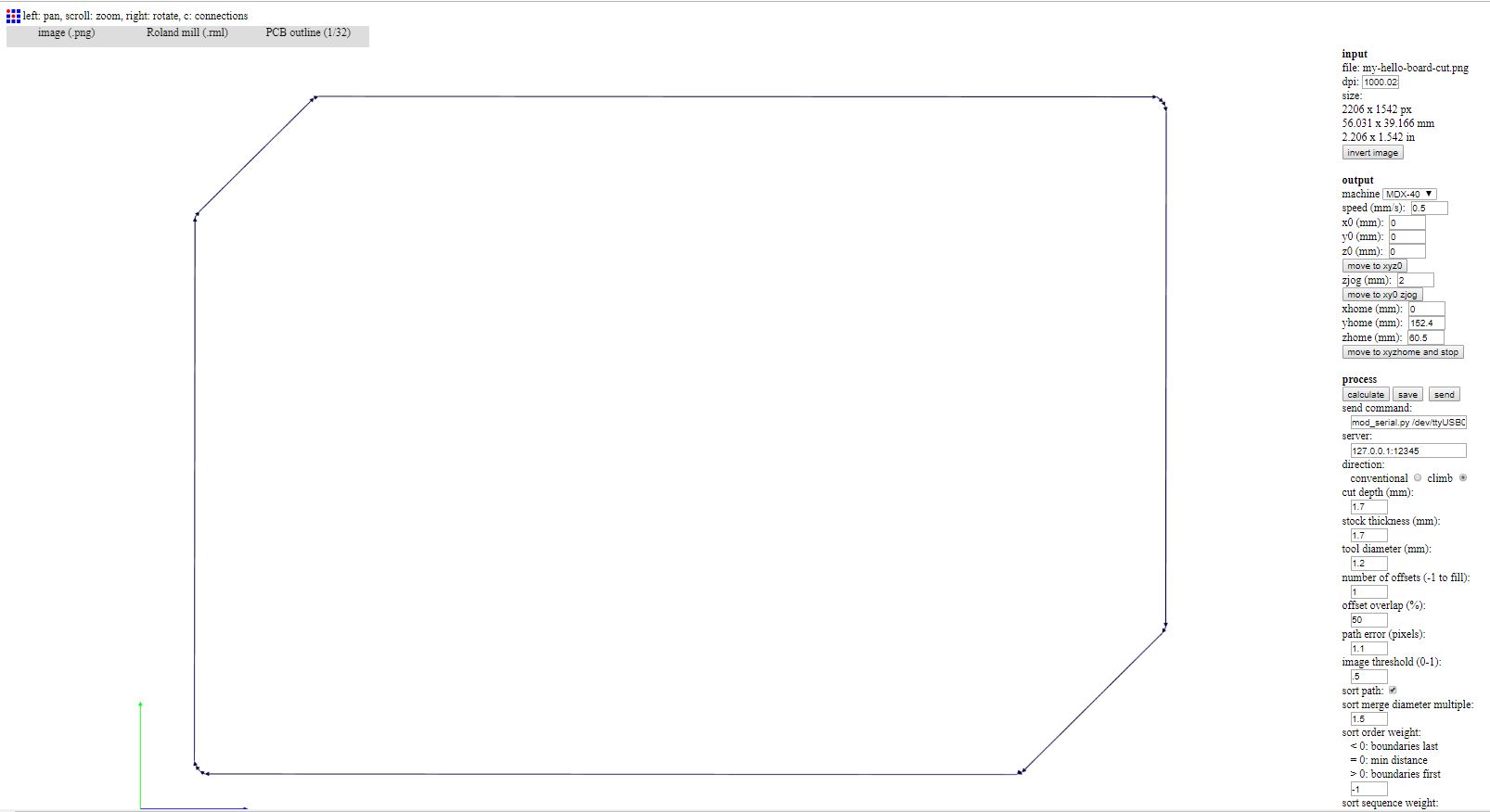
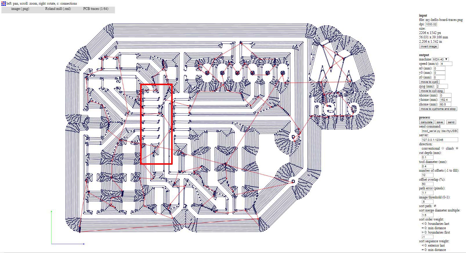
Now I will export the image to png and make sure that it is in Monochrome and the Resolution is set to 1000 dpi
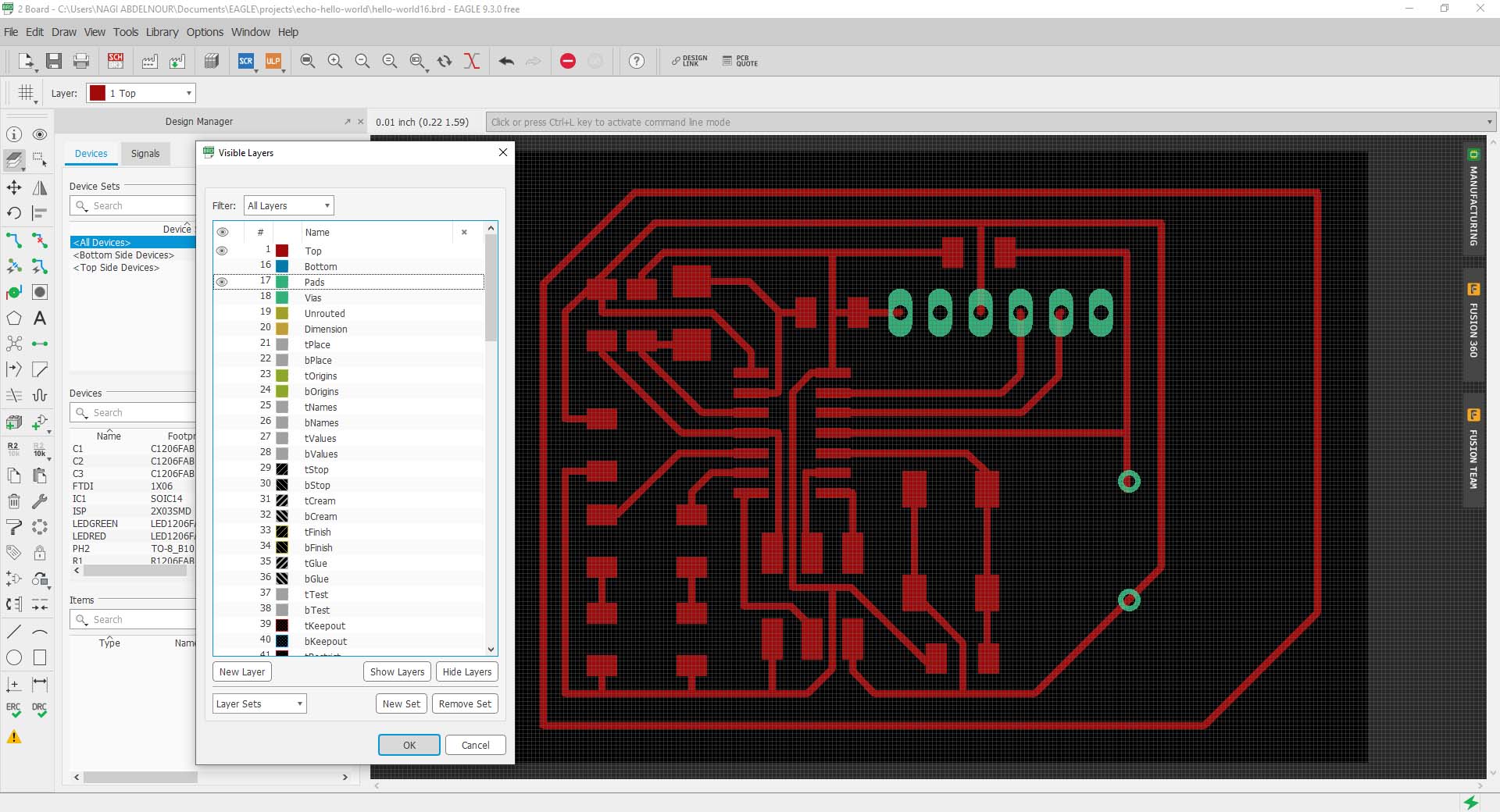
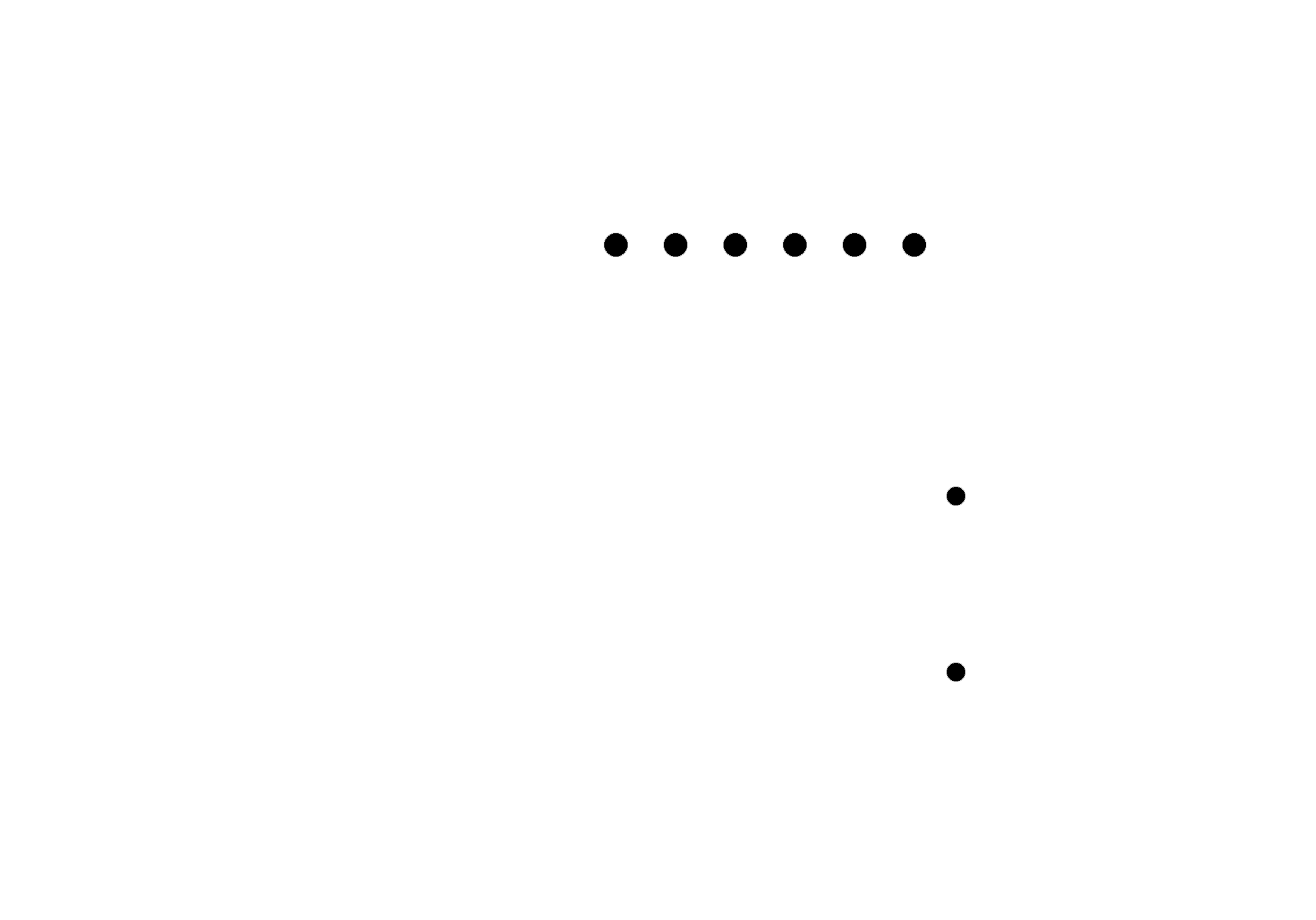
Then I will turn off all the layers except the Pads layer and then I will export the image to png and make sure that it is in Monochrome and the Resolution is set to 1000 dpi(this is for the Drill)
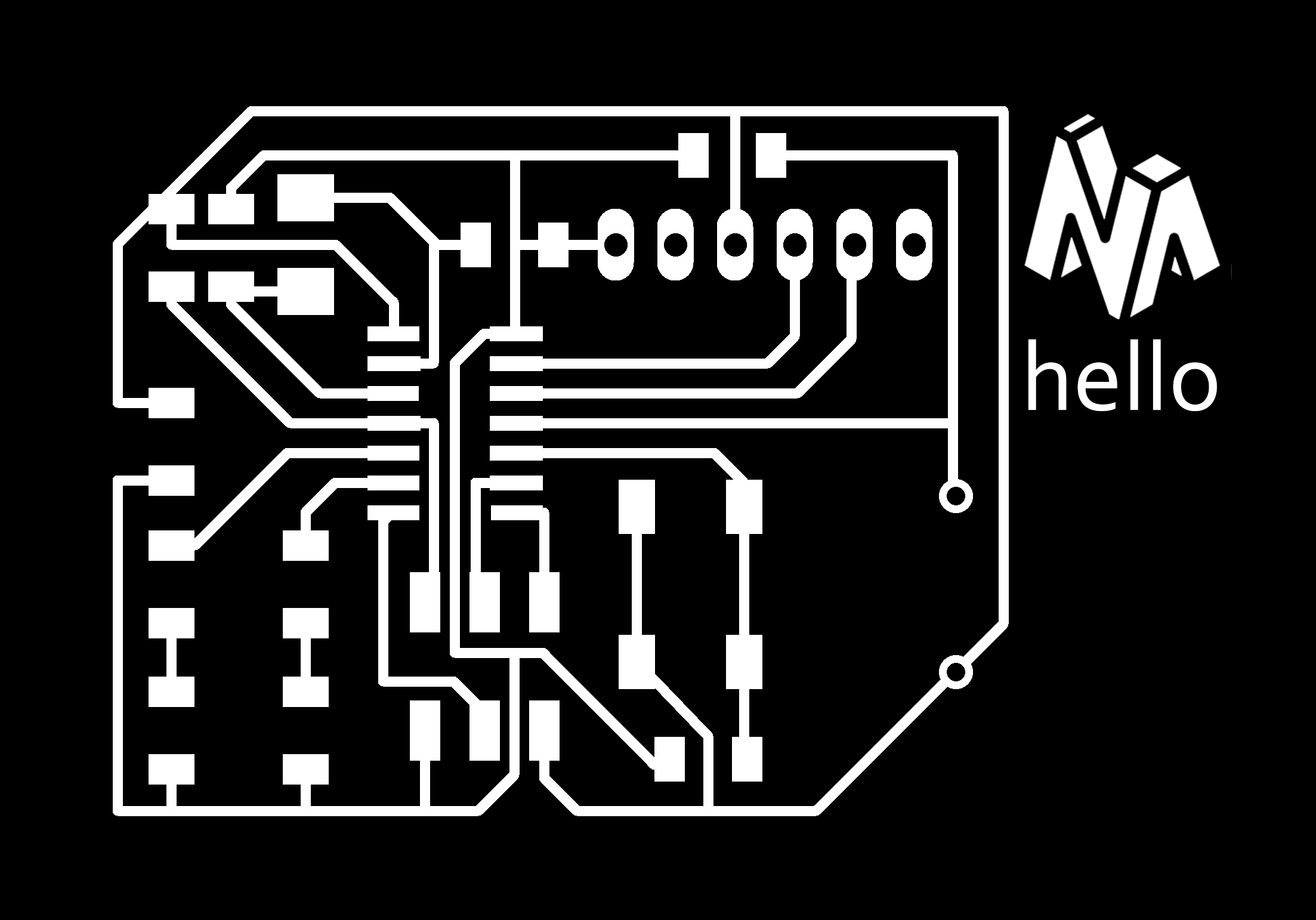
To do the cutout I will create a new layer and name it CUT then change the border polyline I want (color grey in the below image) to the layer CUT(select => right-click => properties).
Now I can isolate it and export the image to png (as the cutout image) and also make sure that it is in Monochrome and the Resolution is set to 1000 dpi(this is for the Drill)
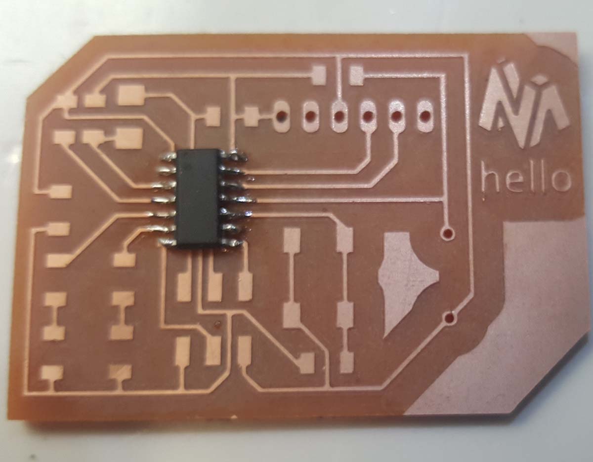
4-The Execution
Milling the board
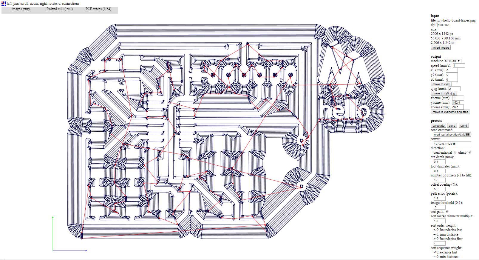
Now that I have the Traces and the Drill png images I can now adjust them on Photoshop and get the g-code in order to produce the board on the milling machine.I will add my logo and Hello text on Photoshop.
Refer to week 5 Electronics Production
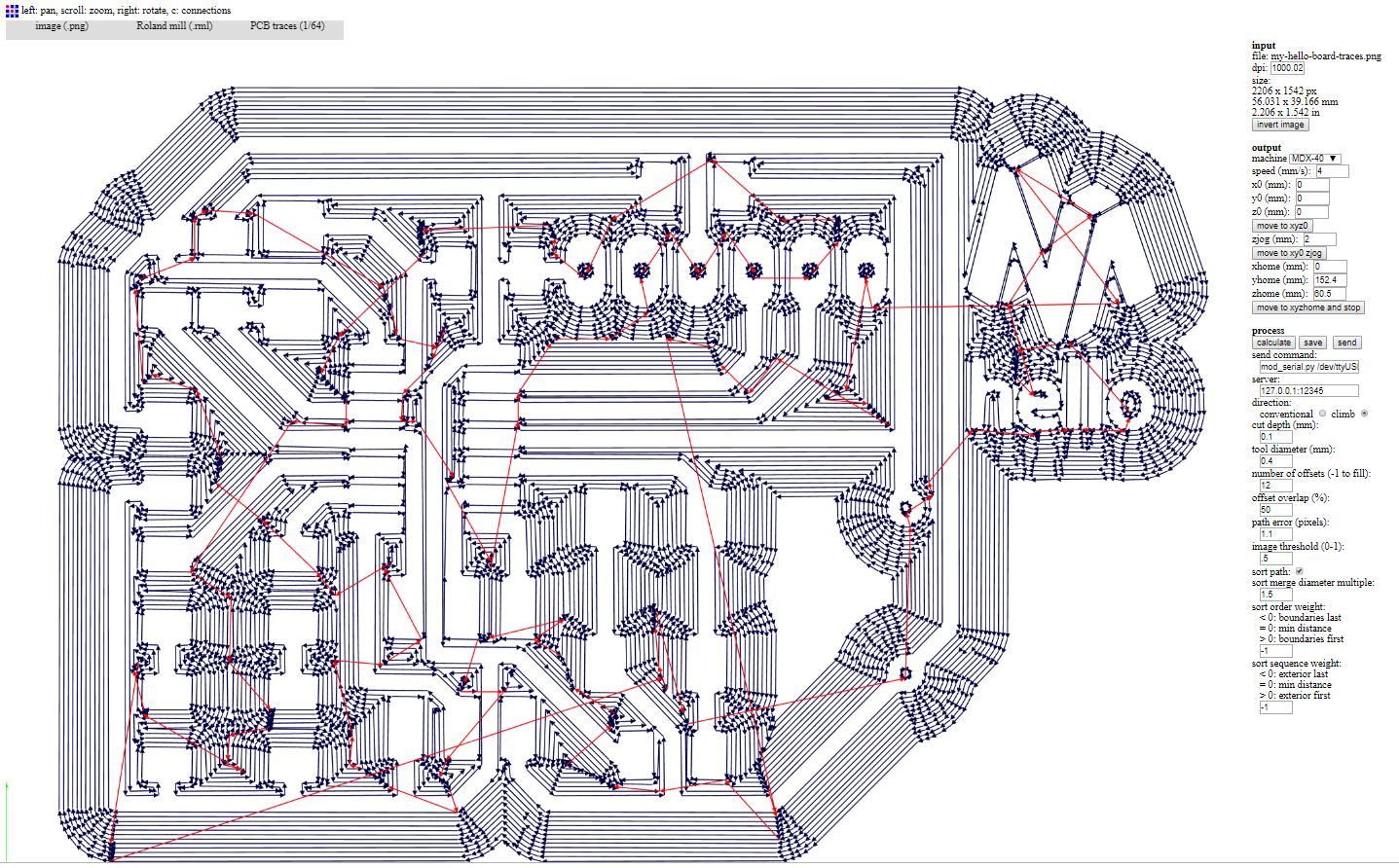
Traces image & g-code setttings

Drill image & g-code setttings
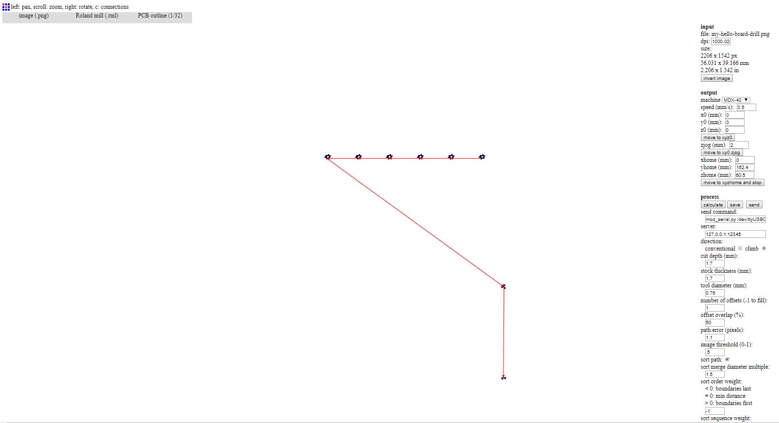
Cutout image & g-code setttings
The Bit rotating speed is set to 5000 RPM for the traces and 10000 RPM for the drilling and external cutout
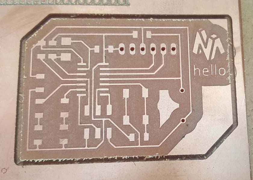
After I finished milling, I noticed a Problem, some circuit are touching each others when generating the g-code
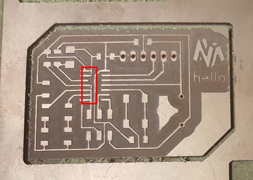
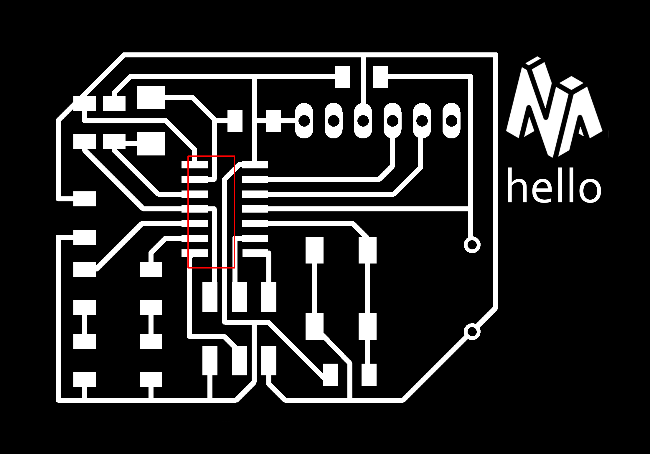
So I went back to Photoshop adjusted the spacing between the lines and generate the g-code again.(Another suggested solution is to set the clearance to 17mil in the design rules on Eagle and set the grid to 2mil or adjust the tool diameter to 0.39mm or less instead of 0.4mm on fab module.)
The new result for tracing and drilling
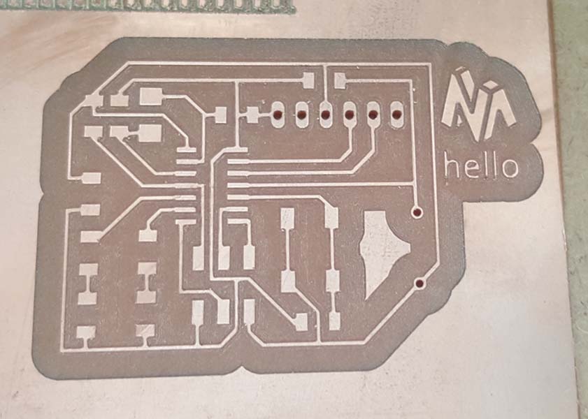
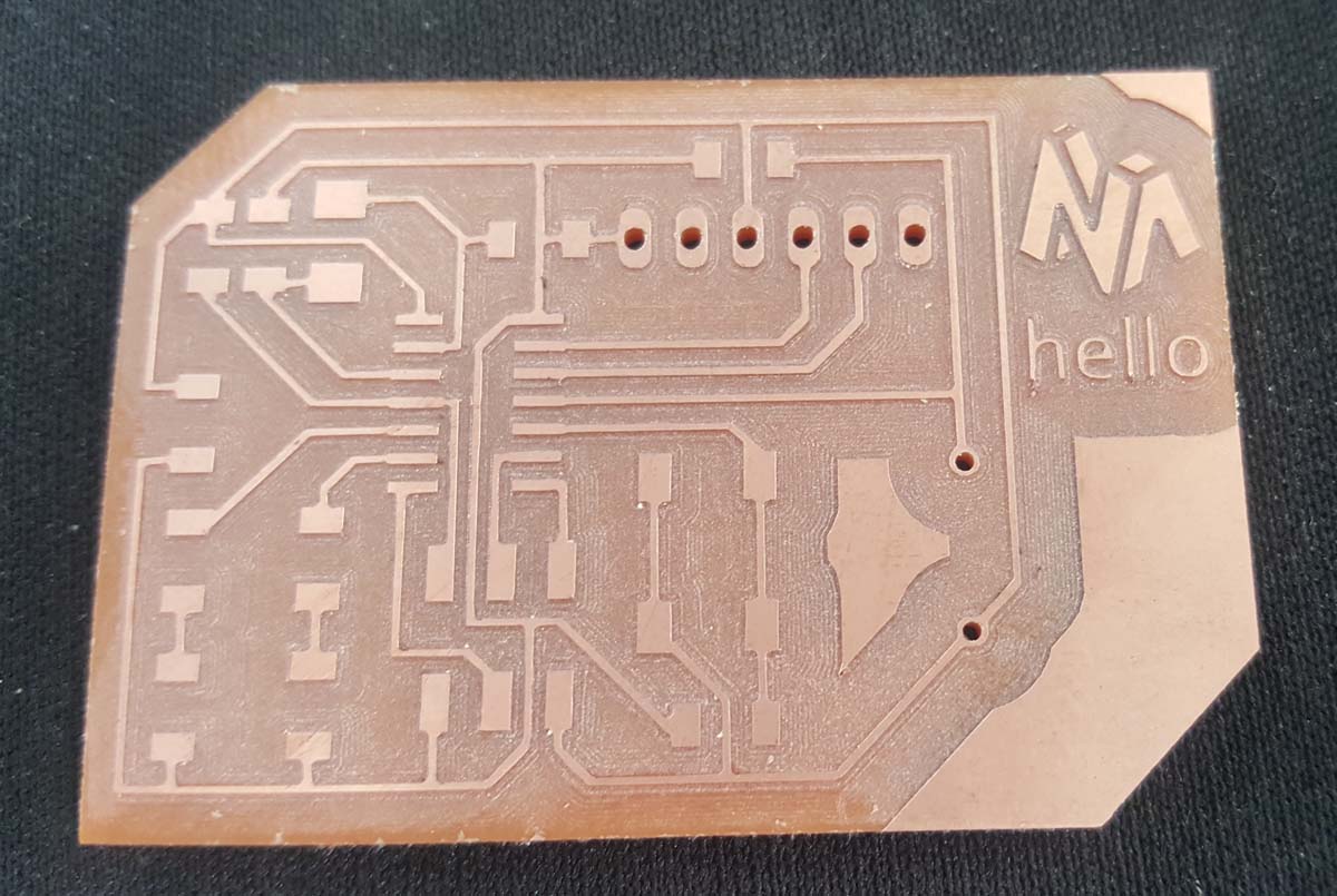
The result for cutting
And the final result
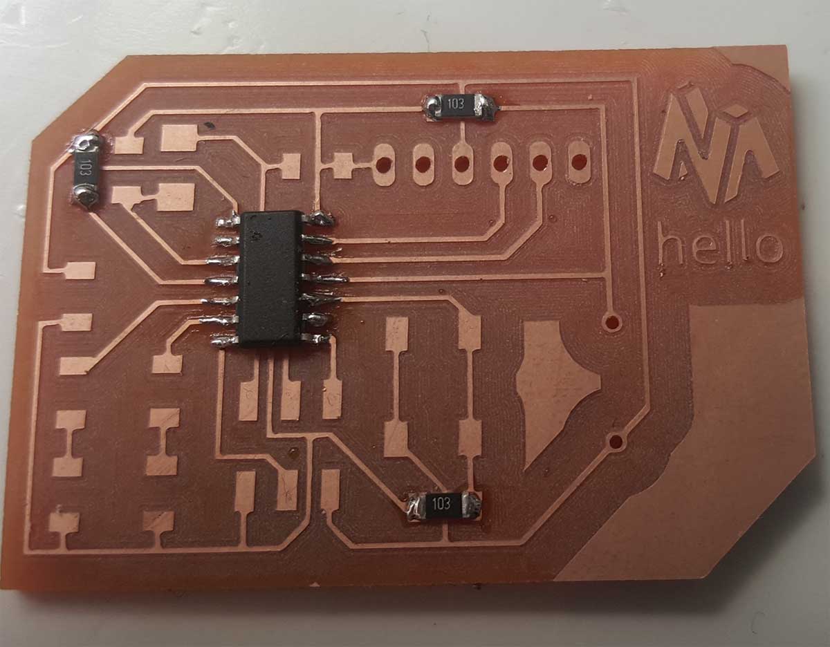
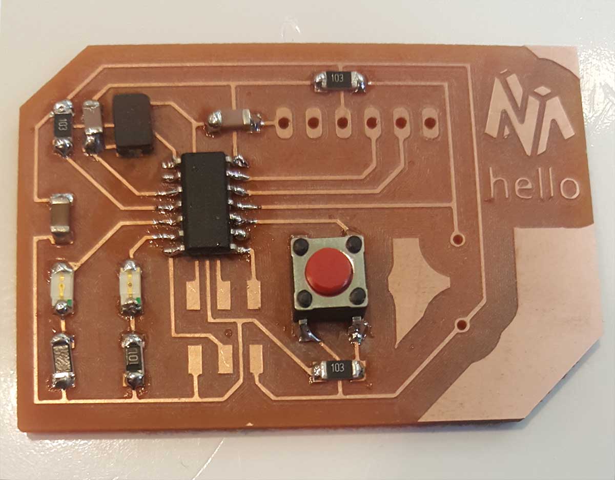
Soldering the components
After entering all the components values in the sketch
I will go to the board and Isolate the pads, the dimension, the tPalce, the tNames, the tValues and export the image to png
In Photoshop I will add this image as a layer to the main board file and give this layer an opacity of 50% so I can see the light traces with Pad names underneath (I already exported this image in color).
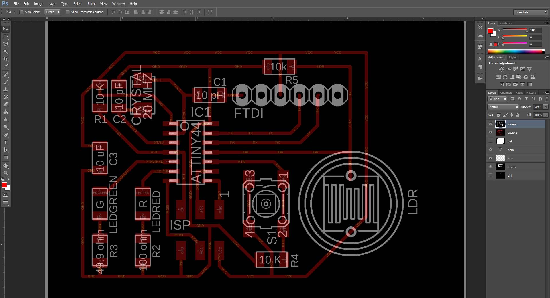
I will save this image and it will be my blueprint reference when I am soldering.

Installing the software
The conncetions:
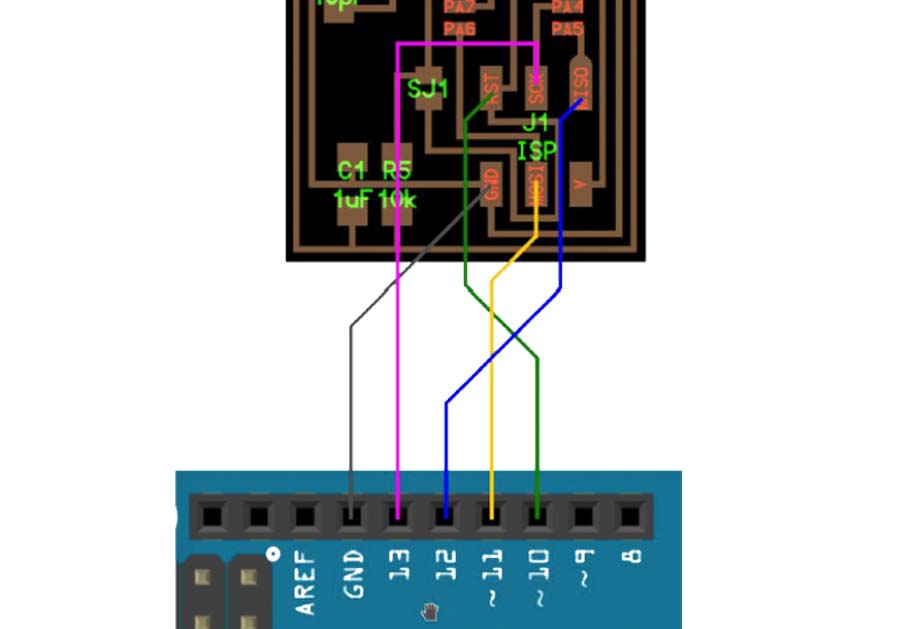
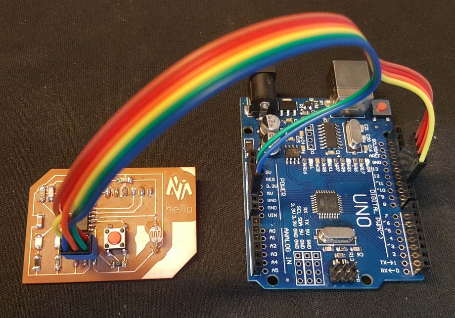
- GND on my board to GND on Arduino (Blue cable)
- RST on my board to Pin 10 on Arduino (Yellow cable)
- MOSI on my board to Pin 11 on Arduino (Orange cable)
- SKC on my board to Pin 13 on Arduino (Brown cable)
- VCC on my board to VCC on Arduino (Green cable)
- MISO on my board to Pin 12 on Arduino (Red cable)
Arduino Setup
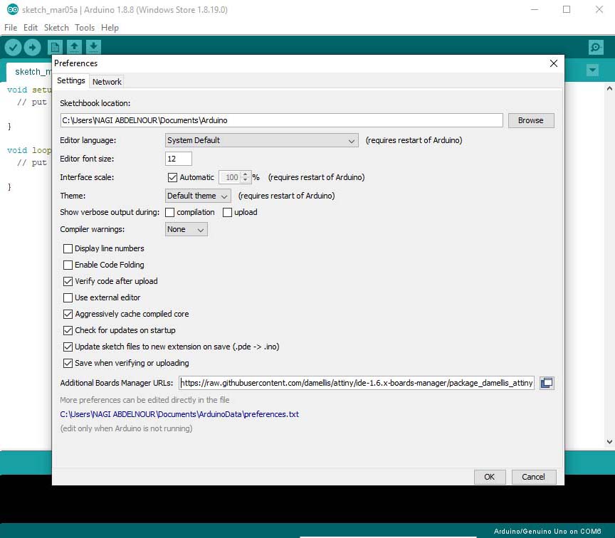
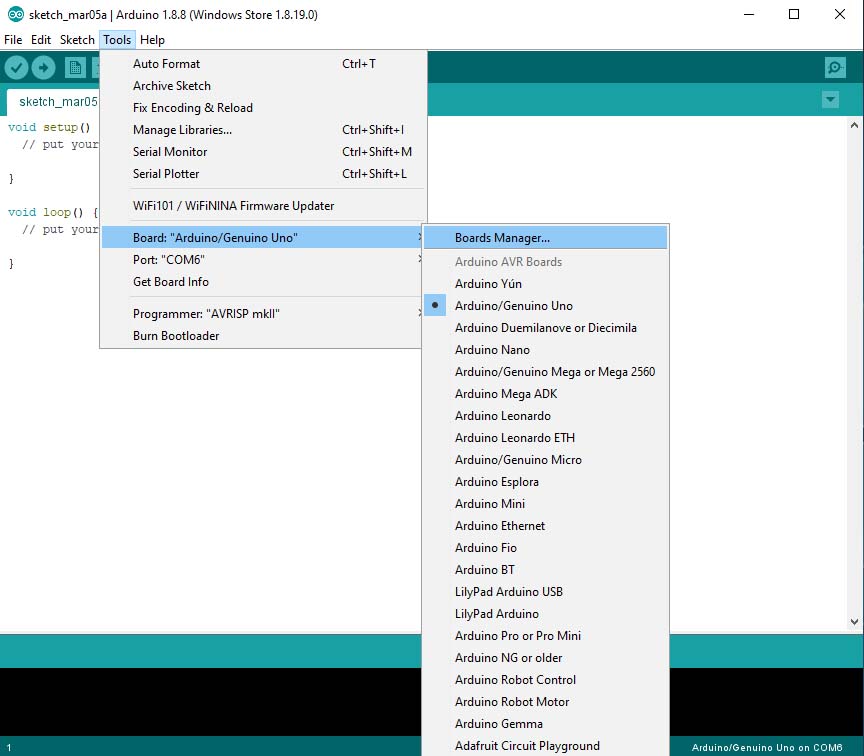
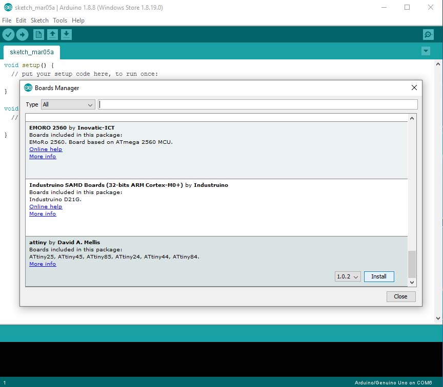
The first thing to do is to install ATtiny44 board on the Arduino IDE. For that we go to settings and insert this link: "https://raw.githubusercontent.com/damellis/attiny/ide-1.6.x-boards-manager/package_damellis_attiny_index.json" in the additional board URL then go to tools => boards manager.
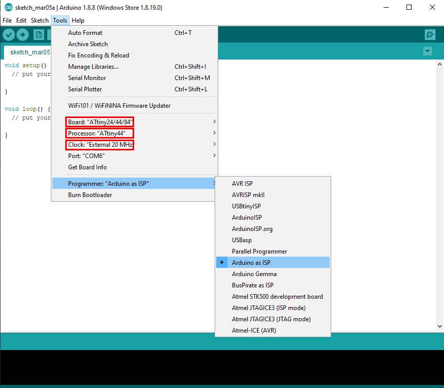
Now we install ATtiny program, then go to tools set the board ,the processor and the clock of my hello board.
Then set the programmer "Arduino as ISP".
And finally remember to go to tool => burn bootloader for the first time I am programing my hello board or when I want to reset it.
Programing and Upload
Below are the similar points between My hello board Pins and Arduino Pins:
- Pin5 is for Green LED in my board and will be Pin8 on Arduino.
- Pin6 is for Red LED in my board and will be Pin7 on Arduino.
- Pin10 is for Push Button in my board and will be Pin3 on Arduino.
- Pin11 is for LDR in my board and will be Pin2 on Arduino.
So I have to enter Arduino pin numbers in the coding and below is the code used for testing:
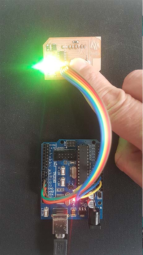
The 2 leds should light when I push the button and the Leds should turn off when I release the Button with a delay of 2000.
                // constants won't change. Used here to set a pin number:
                const int buttonPin = 3;//the number of the pushbutton pin
                const int ldrPin = 2;//the number of LDR pin
                const int ledPingreen = 8;// the number of the greenLED pin
                const int ledPinred = 7;// the number of the redLED pin
                // Variables will change:
                int ledState = LOW; // ledState used to set the LED
                int buttonState = 0;
                int sensorValue = 0; // variable to store the value coming from the sensor

                void setup()
                {
                // put your setup code here, to run once:
                // set the digital pin as output:
                pinMode(ledPingreen, OUTPUT);
                pinMode(ledPinred, OUTPUT);
                // set the digital pin as input:
                pinMode(buttonPin, INPUT);
                pinMode(ldrPin, INPUT);
                }

                void loop()
                {
                // read the state of the pushbutton value:
                buttonState = digitalRead(buttonPin);
                // check if the pushbutton is pressed. If it is, the buttonState is HIGH:
                if (buttonState == HIGH)
                {
                // put your main code here, to run repeatedly:
                digitalWrite(ledPingreen, HIGH); // turn the LED on (HIGH is the voltage level)
                digitalWrite(ledPinred, HIGH); // turn the LED on (HIGH is the voltage level)
                delay(2000);
                }
                else
                {
                digitalWrite(ledPingreen, LOW); // turn the LED off by making the voltage LOW
                digitalWrite(ledPinred, LOW); // turn the LED off by making the voltage LOW
                }
                // wait for a second
                }
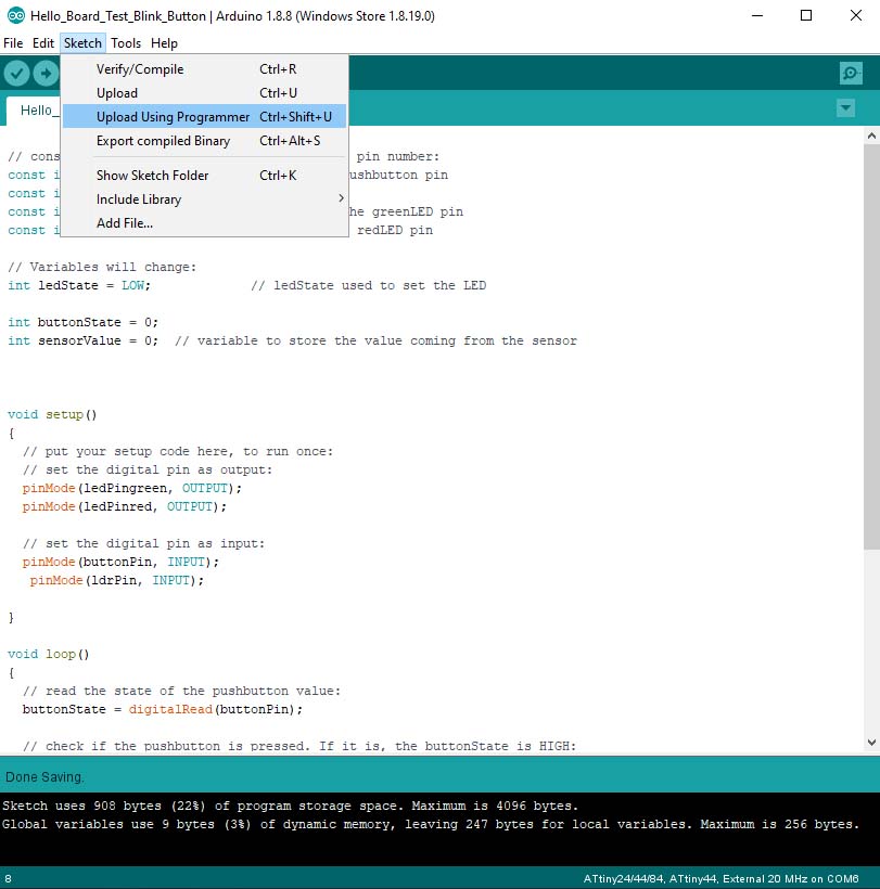
After writing the code I upload it by going to sketch => Upload Using Programmer and I test it ... :)
Note that the Arduino should be set as ISP and should upload the ArduinoISP code to the Arduino before 'Uploading Using Programmer'.
Group Assignment
Use the test equipment in your lab to observe the operation of a microcontroller circuit board
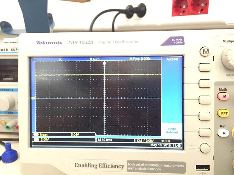
Testing input voltage
We connected the Positive Probe of the Tektronix TBS1052B to on the Vcc of the board and the Negative Probe to the Gnd of the board and we read the 5v signal on the screen.
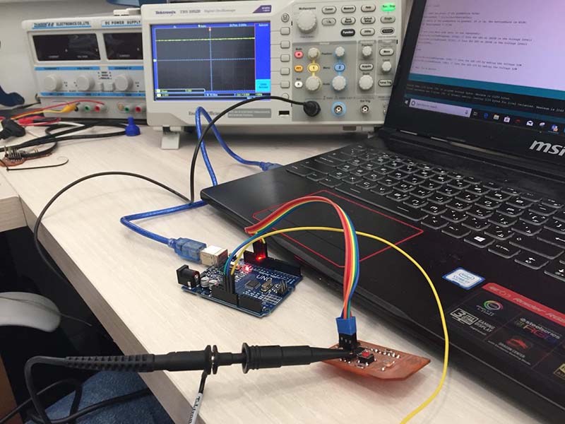
Testing SCK Pin
Here we connected the Positive Probe to the SCK Pin on the board and we read the signal while uploading the code.
Testing On/Off Led
Here we connected the Positive Probe to the LED on the board and we read the signal while pushing the switch button on and off: the code used is a simple push switch button code.
Testing Blinking Led
Here we connected the Positive Probe to the LED on the board and we read the signal while the led is blinking:the code used is a simple blink code
Files
Click Here to download my EAGLE File
Click Here to download my-hello board traces
Click Here to download my-hello board drill
Click Here to download my-hello board cut