Assignment
individual assignment:
design, build, and connect wired or wireless node(s)
with network or bus addresses
group assignment:
send a message between two projects Propose a final project masterpiece that integrates the range of units covered,
Individual assignment
In this assignment I will do some research on the Serial UART Connection, the Serial Peripheral Interface (SPI), and the I2C connection.
Than I will test the Bluetooth Connection
Serial UART Connection
What UART serial communication?
UART stands for Universal Asynchronous Reception and Transmission. Serial communication is the process of sending data one bit at a time, sequentially, over a communication channel. It uses two wires to implement an asynchronous full duplex communication, but only between two devices.
Serial connection
A serial bus consists of just two wires: TX and RX.
- TX - is the Transmitter.
- RX - is the Receiver.
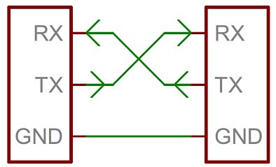
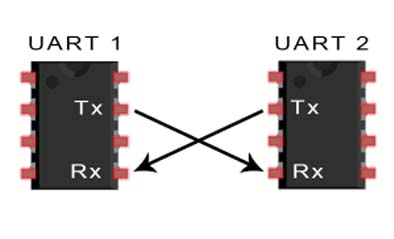
The Serial is only between two devices
Serial connection Testing
Here I will connect my B1 Board done on week 12 with my Hello Board done on week 7
And now I will connect the 2 Boards:
- GND to GND (brown wire)
- VCC to VCC (red wire)
- TX from B1 to RX on hello board (orange wire)
- RX from B1 Board to TX on hello board(yellow wire)
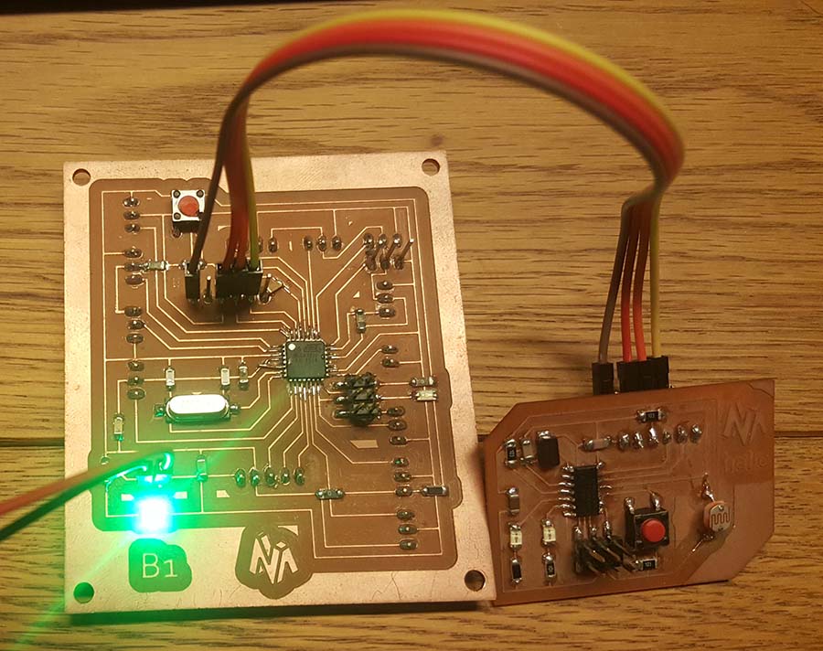
My B1 Board will be the master and it will receive signal from the Hello Board to turn the led. And below is the code used.
                      #include// serial library
                      int led = 13;// declaring the LED pin
                      char ON = '1';// declaring that  ONturnon is the char the will be received.
                      SoftwareSerial myserial(0, 1);

                      void setup() {
                      myserial.begin(9600);
                      pinMode(led, OUTPUT);
                     }

                      void loop()
                     {
                     char chr = myserial.read();// chr will be equal to which the serial will read
                     if (chr ==  ON) {// if the chr have the same value of ON, the LED will be ON.
                    digitalWrite(led, HIGH);
                    delay(100);
                     }
                    else {
                    digitalWrite(led, LOW);
                    }
                    }
My hello Board will be the slave and it will send signal to the B1 Board to turn the led when I push the button. And below is the code used.
                      #include// serial library
                      int bp = 3;// declare that bp(pushbutton)is in pin 3
                      SoftwareSerial myserial(0, 1); // define the serial and the TX=1 and RX=0

                      void setup() {
                      pinMode(bp,INPUT_PULLUP) ;// Declare that push button is an input
                      myserial.begin(9600);
                      }

                      void loop() {
                      int bps = 0;
                      bps = digitalRead(bp);
                      if (bps == HIGH) //if the pushbutton is pressed this condition will be true
                      {
                      myserial.write('1');// send this char
                      }
                     else
                     { myserial.write('0');//if the pushbutton is not pressed sen this char
                     }
                     delay(100);
                     }
And this is the result
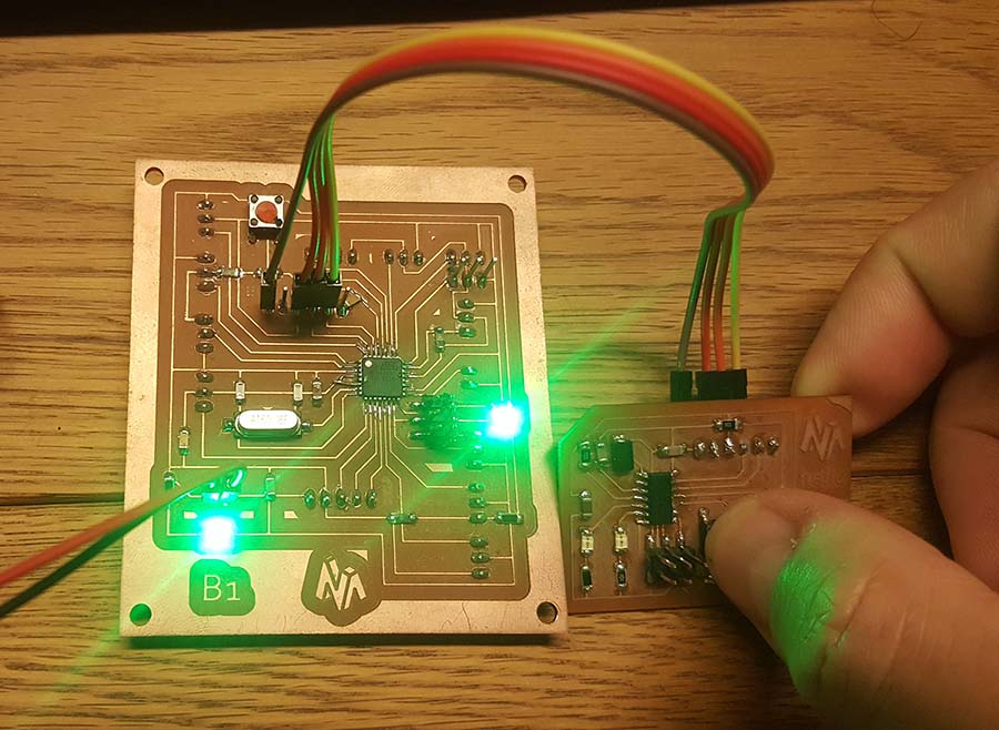
And note that if I unplug the orange wire from both boards it will still working because the yellow wire on the hello board is the transmitter TX and and it is connected to the receiver RX on the B1 Board and in the code it is only the hello board that is tranmitting to the B1 board (one way communication in this case)
Check Sparkfun / Serial for more details.
Check BASICS OF UART COMMUNICATION for more details.
Check circuitdigest.com for more details on programming.
Serial Peripheral Interface (SPI)
What is SPI?
SPI (Serial Peripheral Interface) is a serial communication protocol. SPI interface was found by Motorola in 1970. SPI has a full duplex connection, which means that the data is sent and received simultaneously. That is a master can send data to slave and a slave can send data to master simultaneously. SPI is synchronous serial communication means the clock is required for communication purpose.
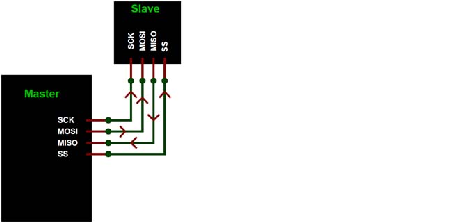
SPI connection
A SPI has a master/Slave communication by using four lines: MISO, MOSI, SS, and CLK
- MISO (Master in Slave Out) - The Slave line for sending data to the master.
- MOSI (Master Out Slave In) - The Master line for sending data to the peripherals.
- SCK (Serial Clock) - The clock pulses which synchronize data transmission generated by the master.
- SS (Slave Select) –Master can use this pin to enable and disable specific devices.
The GND should always be shared between the devices
A SPI can have only one master and can have multiple slaves.
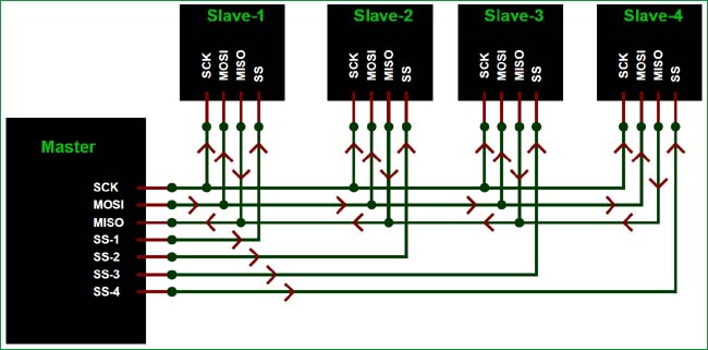
To start communication between master and slave we need to set the required device's Slave Select (SS) pin to LOW, so that it can communicate with the master. When it's high, it ignores the master. This allows you to have multiple SPI devices sharing the same MISO, MOSI, and CLK lines of master. As you can see in the above image there are four slaves in which the SCLK, MISO, MOSI are common connected to master and the SS of each slave is connected separately to individual SS pins (SS1, SS2, SS3) of master. By setting the required SS pin LOW a master can communicate with that slave.
Check Sparkfun / Serial Peripheral Interface (SPI) for more details.
Check BASICS OF THE SPI COMMUNICATION PROTOCOL for more details.
Check circuitdigest.com for more details on programming.
I2C
What is I2C connection?
I²C (Inter-Integrated Circuit), pronounced I-squared-C, is a synchronous, multi-master, multi-slave, packet switched, single-ended, serial computer bus invented in 1982 by Philips Semiconductor (now NXP Semiconductors).
It is widely used for attaching lower-speed peripheral ICs to processors and microcontrollers in short-distance, intra-board communication.
Alternatively I²C is spelled I2C (pronounced I-two-C) or IIC (pronounced I-I-C).
Source Wikipedia
I2C connection
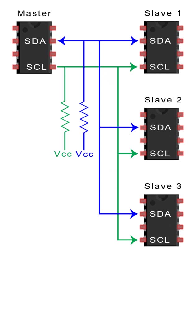
I2C is a synchronous communication protocol meaning, both the devices that are sharing the information must share a common clock signal. It has only two wires to share information : SCL and SDA
- SCL - is used for the clock signal.
- SDA - is used for sending and receiving data.
The GND should always be shared between the devices
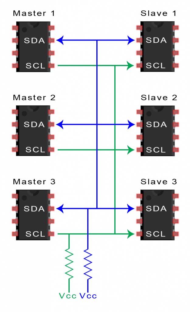
A I2C can have multiple master and multiple slaves.
I2C Testing
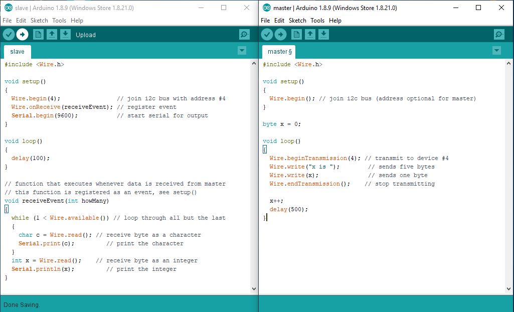
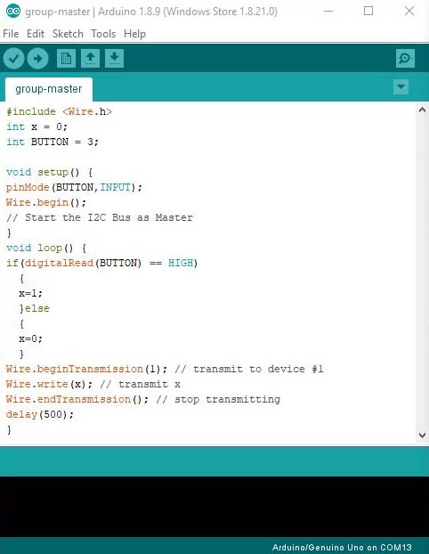
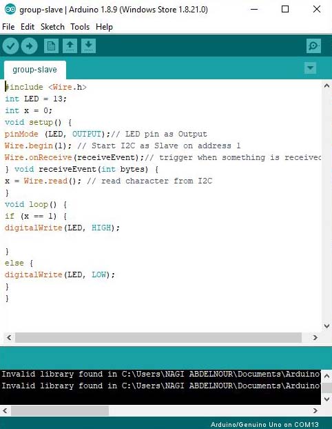
Below are the Mater and Slave codes tested on the two Arduino Boards
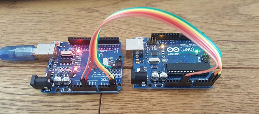
And now I will connect the 2 Boards:
- VCC to VCC (brown wire)
- GND to GND (red wire)
- A4(SDA) to A4 (orange wire)
- A5(SCL) to A5 (yellow wire)
The master code is sending the x value which is incrementing at each loop and the slave is receiving the values and printing them on the serial monitor
After trying it on the Arduino, I will connect my board B1 done in the output week as master and use the Arduino as slave.
And this is the test result
Check Sparkfun / I2C for more details.
Check BASICS OF THE I2C COMMUNICATION PROTOCOL for more details.
Check circuitdigest.com for more details on programming.
UART vs SPI vs I2C | Difference between UART,SPI and I2C
Check rfwireless-world.com that shows a comparison table between the 3 different connections.
Bluetooth connection
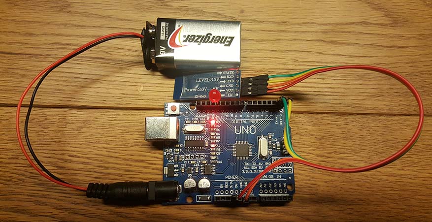
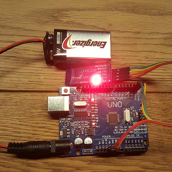
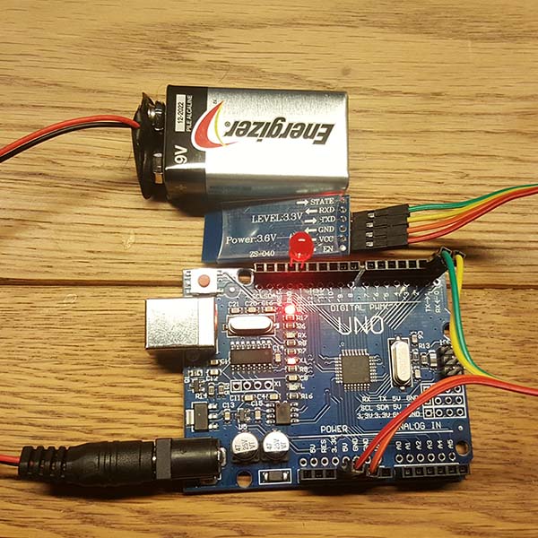
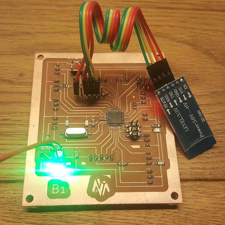
I will use the HC-06 bluetooth module with Arduino Board and the connections are as follow:
- GND to Gnd
- VCC to VCC (3.3V)
- RX on the HC-06 goes to the TX/pin1 on Arduino
- TX on the HC-06 goes to the RX/pin0 on Arduino
And I will upload the following code to the Arduino Board
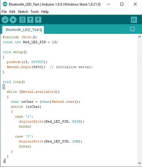
The Led will turn on when we type 1 on the serial and it will turn off when we type 0.
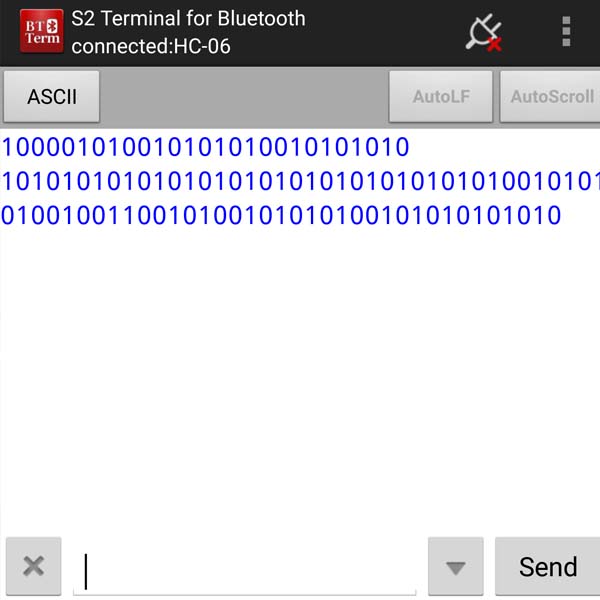
For that I will download 'S2 Terminal for Bluetooth' application on my smart phone
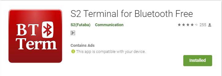
On the application I will connect to my bluetooth and enter 1234 for the Pin code
Than switch to ASCII and type 1 turn on the led and then type 0 to turn off the led
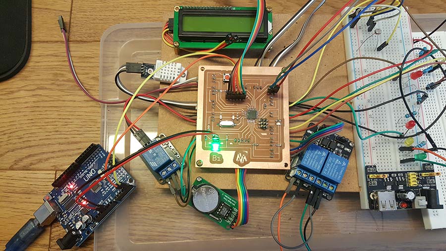
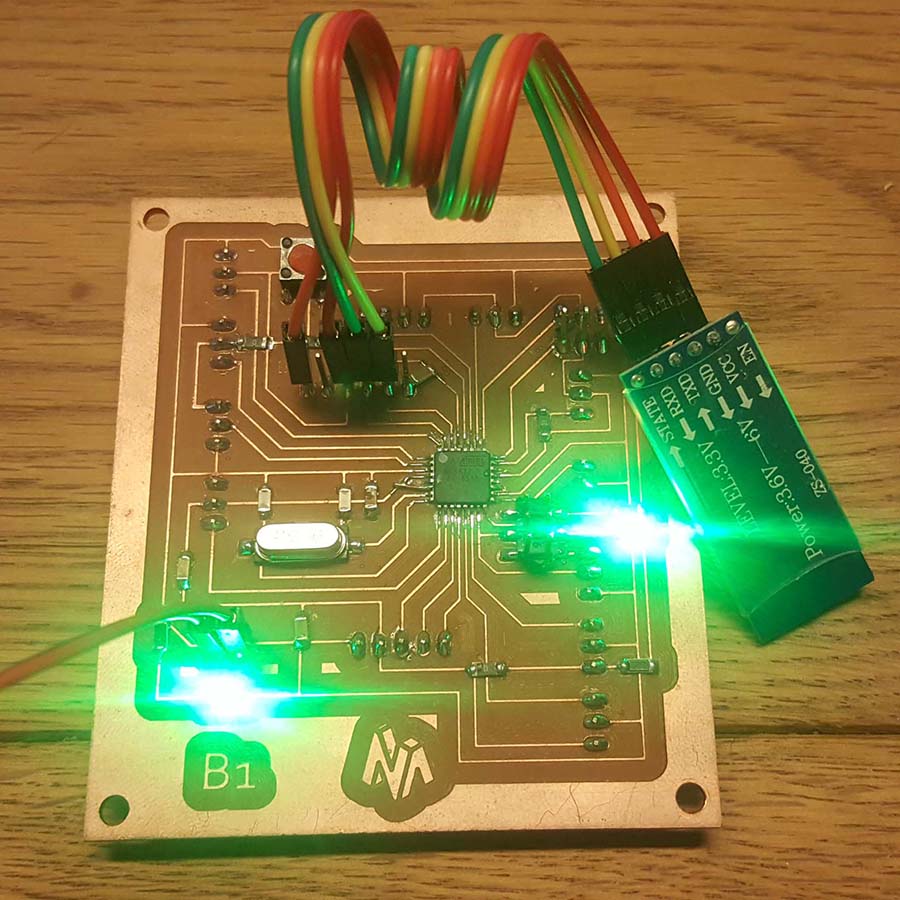
And this is the test done with my B1 Board
Group assignment
Send a message between two projects Propose a final project masterpiece that integrates the range of units covered,
I will use my Board B1 and connect it to Joe's Board using I2C connection: Joe's board will be the master with a push button connected to it and my Board will be the slave with the led connected on pin13. It will turn on when we push the button on the master baord and below are the codes:
And now I will connect the 2 Boards:
- VCC to VCC (blue wire)
- GND to GND (purple wire)
- A4(SDA) to A4 (green wire)
- A5(SCL) to A5 (yellow wire)
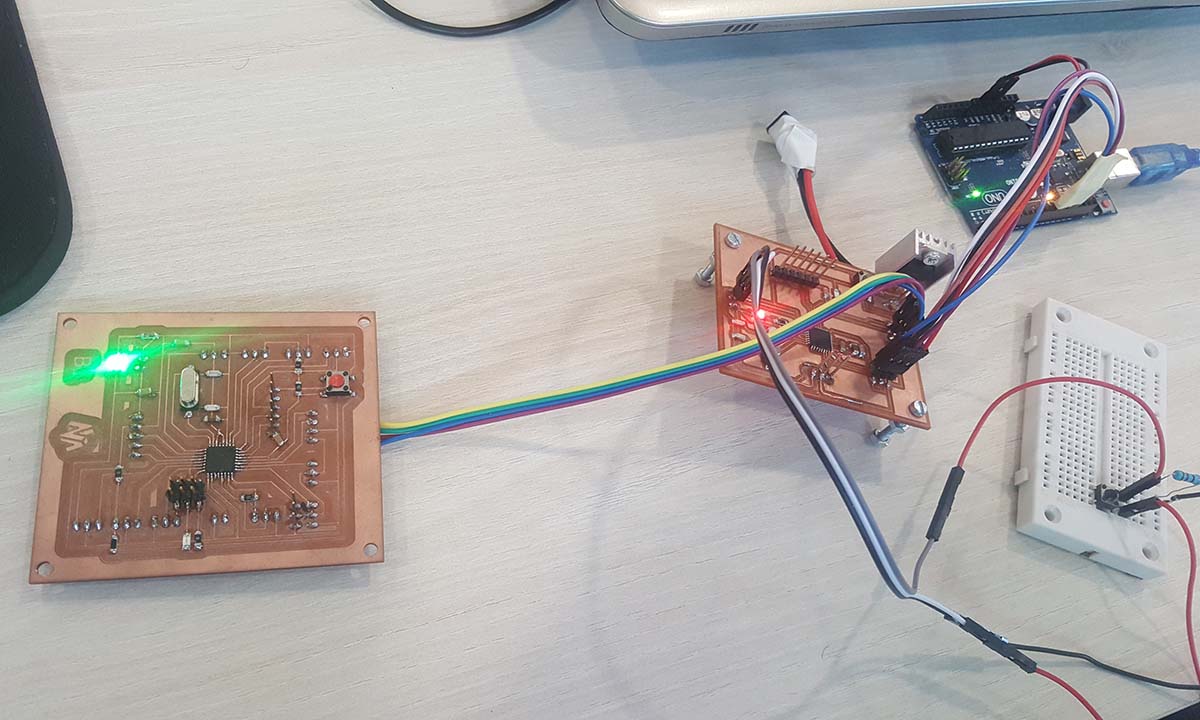
And this is the result:
Files
Click Here to download the Master code
Click Here to download the Slave code
Click Here to download the Bluetooth code
Click Here to download the Group Master code
Click Here to download the Group Slave code