12. Output devices
Objectives of this week are:
1- To add an output device to a microcontroller board we’ve designed, and program it to do something.
2- As group, measure the power consumption of an output device.
Group assignment
Please check the group assignment here.
4x20 LCD
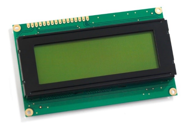
For this week, the LCD has been used as ouput. LCD stands for liquid Crystal Display and it comes with blue panel and white LED backlight. It operates at 5 volts and 1.5 mA supply current. The voltage at all its input pins is between 2.2 to 5.5V, and its maximum LED forward voltage is 3.4V and the maximum forward current is 20mA. The 4x20 LCD has been used here instead of the 2x16 LCD in order to be able to display more characters on the screen at the same time. This LCD enable us to display 80 characters as 4 x 20 = 80.
The LCD has a parallel interface that consists of the following pins:
1- (RS) pin which is a register selects pin that controls where in the LCD’s memory the data is written to. It can be selected either the data register, which holds what goes on the screen or an instruction register, which is where the LCD’s controller looks for instructions on what to do next.
2- (R/W) pin which is the Read/Write pin that selects reading mode or writing mode.
3- An Enable pin that enables writing to the registers.
4- (D0 -D7) eight data pins. The states of these pins (high or low) are the bits that when the user write to a register or read.
5- There is also a display contrast pin (V0), power supply pins (+5V and GND) and LED Backlight (BKL+ and BKL-) pins that can be used to power the LCD, control the display contrast, and turn on and off the LED backlight, respectively.
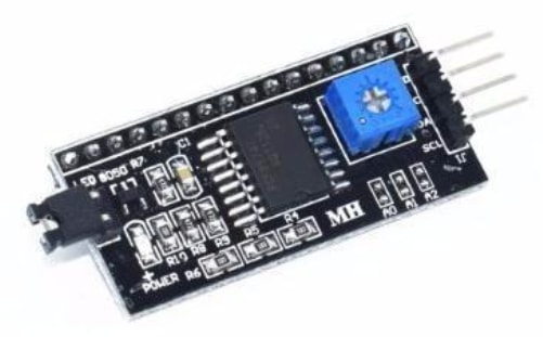
To reduce the amount of wires and connections to the microcontroller, I2C communication method has been used by connecting the I2C LCD module with the pins of the LCD.
The module is supplied with 5 volts. The brain is a PCF8574T 8-bit I2C GPIO expander wired up for 4-bit communication with the LCD. The register layout is: D7, D6, D5, D4, BACKLIGHT (wired to V0), E (clock/enable), R/W (direction), RS (command/data mode). For writing to the LCD, data is read out of the interface on the falling edge of the ENABLE bit. The I2C address of this module is 0x27.
Both the LCD and I2C chip are showing in the figures below:
1) The lcd:
2) The I2C module:
Connection & Programming
Overview
The module has 4 pins to be connected with the micro-controller: VCC, GND, SDA and SCL. Vcc is the supply pin and it has been connected with the 5 volts pin of the microcontroller. GND is the ground pin and it has been connected to the ground pin. SDA is the data line as the data (the 8 bits) are placed on the SDA line starting with the MSB (Most Significant Bit). While the SCL is the clock line, it pulsed high, then low, then high, then low and so on. Hence, the LCD has been connected with my own ardunio board that has been made in week11 as following:
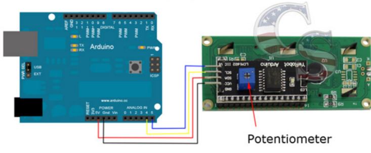
| I2C LCD module pins | micro-controller pins |
|---|---|
| VCC | VCC |
| GND | GND |
| SDA | A5 |
| SCL | A4 |
Workflow
Steps of connection:
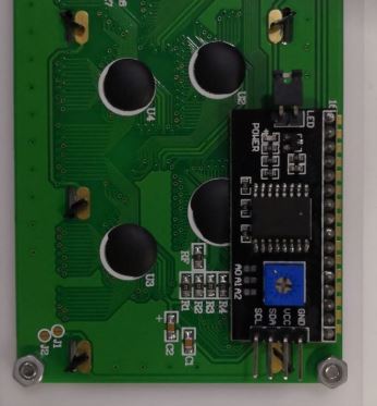
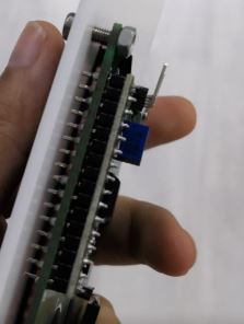
1- I have started by soldering the I2C module with the LCD
2- I have connected the programmer to my PC.
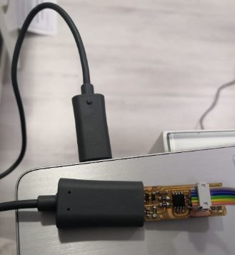
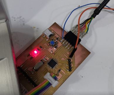
3- I have connected the programmer to the ISP headers of my own ardunio baord.
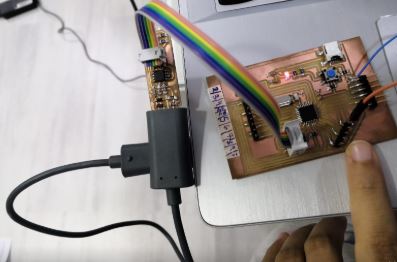
4- I have connected the FTDI cable to my own ardunio board for serial monitoring and to provide power to my circuit.
5- I have connected the LCD I2C module to my micro-controller board as explained earlier.
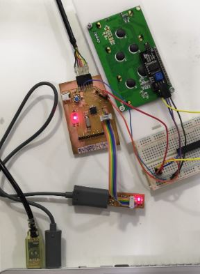
6- I have uplaoded the code.
#include <Wire.h>
#include <LiquidCrystal_I2C.h>
//I2C pins declaration
LiquidCrystal_I2C lcd(0x27,20,4); //set the I2C address 0x27 and the LCD used is 4x20

void setup()
{

lcd.begin();   // initialize the lcd.
lcd.backlight(); //set backlight on.

}

void loop()
{
//Write your code
lcd.setCursor(0,0); //Defining positon of the cursor.
lcd.print(" Fab 2019 "); //print the following in the screen
delay(3000);//Delay for 3 sec
lcd.setCursor(0,1);
lcd.print("Bahrain");
delay(3000);
lcd.setCursor(0,2);
lcd.print("Zahra Almukhariq");
delay(3000);
lcd.setCursor(0,3);
lcd.print("Thank you!!");
delay(3000);
}
Testing
LCDtesting from Zahra Almukhariq Page on Vimeo.
Original files
To downlaod the original file of the PCB of my own ardunio board please refer to week11.
To downlaod the original file of the Arduino code click here.