3. Computer Aided Design
Objectives of this week are:
1- Model 2D design of your final project idea.
2- Model 3D design of your final project idea.
2D design
Photoshop
In my 2D design I have started with photoshop because I have a little background on how to use it. In photoshop, each shape, text or object created is called a “layer”. So, I have created my layers (shapes) and joined them together to create my 2D model. This is my final design in photoshop which is basically the front view of the device.
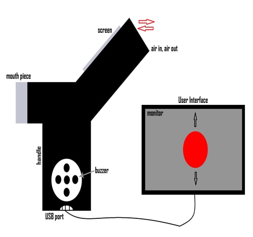
Noticed that my design now is different from what I have sketched before in week 1. This is because I found that designing my device in this way is better in term of getting readings and do some measurements.
So, this is how the photoshop platform look like
.jpg)
On the right-hand side, you can see all the layers in the layer panel and on top of them there is the properties panel. On the left-hand side, there is the tools panel where you can add texts and create artwork. At the very top there is the menu bar and under it is the options bar. All those elements were used to create the 2D model.
- To add a text – go to the tools bar > click on the “T” icon > write your text > edit the font of it, the size and the color from the options bar.
- To create a shape - click on the splash icon (the one above the hand icon) > choose the shape that you want > draw it > change the color of it from the properties panel.
- To edit the size - click on the layer > Ctrl+T > edit the size > apply.
- To duplicate a layer – right click on the layer > choose duplicate > press ok.
- To save your work - go to the menu bar > file > save as > choose the format > press ok.
OpenSCAD
After modeling my project in photoshop, my instructor encouraged me to try another software. He told me about openSCAD. OpenSCAD is a powerful software used for both 2D and 3D CAD models. It is free software and available for Linux/UNIX, Windows and Mac. Unlike photoshop, OpenSCAD is not an interactive modeler. Instead it is something like a 2D/3D-compiler that reads in a script file that describes the object and renders the model from this script file. Within 2D design, I decided to build a box that contains all the components of my first final project prototype. As mentioned earlier, I am planning to build a device that measures different parameters of human lungs. I did my first experiment using a mic to detect the inhaling and exhaling. So, for this task and by using openSCAD, I decided to build the case (box) that contains the circuit of my mic experiment.
- First of all, you need to understand the openSCAD platform. If it’s your first time in using openSCAD, I encourage you to go through this link all3dp. I found this website very helpful as it helped me a lot in getting started with the software and learn about it as a first time user.
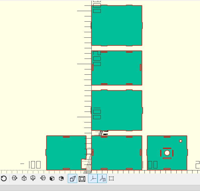
- Secondly, I built the 6 sides of the box using square() command and I started adding parts to it and cutting parts from it using difference() & union() commands.
- This is how my design look like
- And here is the code
l=95; // length in mm
w= 65; //width in mm
h= 75; //height in mm

jx= 12; //cut-off joint
jy= 1.15; //cut-off joint


//base
difference(){
square ([l, w]);
translate([17.75,2,0])
square ([jx,jy]);
translate([65.25,2,0])
square ([jx,jy]);
translate([17.75,(w-jy-2),0])
square ([jx,jy]);
translate([65.25,(w-jy-2),0])
square ([jx,jy]);
translate([(l-jy-2),27.5,0])
square ([jy,jx]);
translate([0+2,27.5,0])
square ([jy,jx]);
}

//front side
 union(){
translate([0,(w+10),0])
square ([l, h]);
translate([17.75,(((w+10))-jy),0])
square ([jx,1.3]);
translate([65.25,(((w+10))-jy),0])
square ([jx,1.3]);
translate([17.75,(w+10+h),0])
square ([jx,1.3]);
translate([65.25,(w+10+h),0])
square ([jx,1.3]);
translate([l,(((w+10)+31.5)),0])
square ([1.3,jx]);
translate([(-jy),((w+10+31.5)),0])
square ([1.3,jx]);
 }

//top side
difference() {
translate([0,w+w+30,0])
square ([l, w]);
translate([17.75,(w+h+20+2),0])
square ([jx,jy]);
translate([65.25,(w+h+20+2),0])
square ([jx,jy]);
translate([17.75,((w+h+w+20)-jy-2),0])
square ([jx,jy]);
translate([65.25,((w+h+w+20)-jy-2),0])
square ([jx,jy]);
translate([(l-jy-2),(w+10+h+10+27.5),0])
square ([jy,jx]);
translate([0+2,(w+10+h+10+27.5),0])
square ([jy,jx]);
}

//back side
union() {
translate([0,w+10+h+10+w+10,0])
square ([l, h]);
translate([17.75,((w+w+h+30)-jy),0])
square ([jx,1.3]);
translate([65.25,((w+w+h+30)-jy),0])
square ([jx,jy]);
translate([17.75,(w+w+h+h+30),0])
square ([jx,1.3]);
translate([65.25,(w+w+h+h+30),0])
square ([jx,1.3]);
translate([l,(w+10+h+10+w+10+31.5),0])
square ([jy,jx]);
translate([(-jy),(w+10+h+10+w+10+31.5),0])
square ([jy,jx]);
}

//left side
module l_side()
{
translate([-85,0,0]) //left side
square ([h, w]);
}

//shapping the l side
difference() {
union() {
l_side();
translate([-10,27.5,0])
square ([jy,jx]);
translate([((-h-10)-jy),27.5,0])
square ([jy,jx]);
}
    translate([(((-10)-h+31.5)),2,0])
    square ([jx,jy]);
    translate([(((-10)-h+31.5)),(w-jy-2),0])
    square ([jx,jy]);
    translate([-19,3,0])
    square ([9,18]);
  }

//right side
module r_side()
{
translate([105,0,0]) //right side
square ([h, w]);
}

//shapping the r side
difference() {
union() {
r_side();
translate([((l+10)-jy),27.5,0])
square ([jy,jx]);
translate([(l+10+h),27.5,0])
square ([jy,jx]);
}
    //cut for the sensor (MIC)
    translate([(l+10+(h/2)),(w/2),0])
    circle(d=9.8);
    //cut for the led
    translate([168,55,0])
    circle(d=4.9);
    translate([(l+10+31.5),(w-jy-2),0])
    square ([jx,jy]);
    translate([(l+10+31.5),2,0])
    square ([jx,jy]);
    translate([(l+10+30),((w/2)+8),0])
    square ([15,1]);
    translate([(l+10+25),26,0])
    square ([1,12]);
    translate([(l+10+47.7),26,0])
    square ([1,12]);
    translate([(l+10+30),22,0])
    square ([15,1]);
  }
And here is the orginal file
3D design
Fusion360
This task was tough for me and a little bit challenging because I do not have any experience or background in 3D design. I have never worked on 3D design before or learnt about it. So, I started by watching some YouTube videos and read about the different 3D software. I decided to start with Fusion 360 because I found a lot of tutorials on it. I started by building random shapes and play around until I did the following:
.jpg)
Fusion360 from Zahra Almukhariq Page on Vimeo.
Here is the orginal file fusion360 file
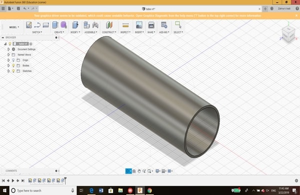
This was just the start and to get familiar with the software. After that, I have learned that for each 3D design, the sketch must be drawn first. My colleague has helped me a lot in learning the basics of 3D design. Therefore, I decided to draw the 3D model of a tube that will be used as a flowmeter in my spirometer project (My final project). Here is the steps on how I designed the tube:
1- I sketched a circle with a diameter of 24 mm, then I have extrude it for 35 mm.
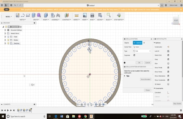
2- Then, on the left side of the object I have sketched a capillary tubes inside the main tube with a diameter of 1.5 mm. For each circle I was creating a pattern, so I did not sketch all of them one by one.
3- Then, I made a cut for around 10 mm.
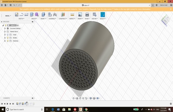
4- Next, on the right side of the object, I have drawn another circle with a diameter of 22 mm. I made a cut to create a cylindrical object (pipe) that has a wall thickness of 2 mm.
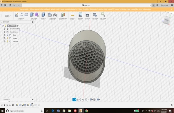
5- Then, I have completed the tube by drawing and extruding another two circles 24 mm and 22 mm with a length of 35 mm as well. That make the total length of the tube equal to 70 mm.
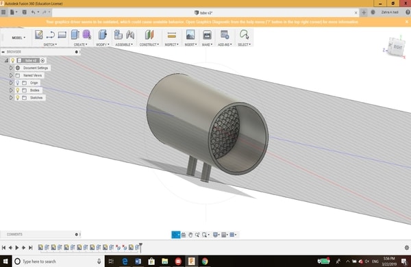
6- Then I have sketched 2 circles to make holes in the tube of 3 mm.
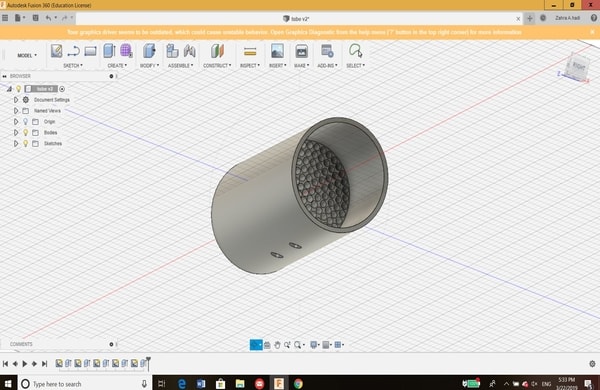
8- After that, another 2 circles have been drawn then extruded. This is how the final design look like
TinkerCAD
Another 3D software that is good for bignners and I have used is Tinkercad. By typing “Tinkercad” on google, you will found and enter it website. The front page of Tinkercad is as following:
Then, I have signed in using my Autodesk account and I got this page, I clicked on “Create new design” to start building my 3D model.
.jpg)
The following picture now shows the software work area. We can see that the basic shapes and components located on the right hand side, the work area is in the middle and on the left hand side there is some of helpful tools such as zoom in, zoom out and flat view option.
.jpg)
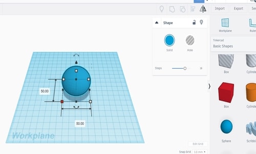
I was planning to draw a snowman, so the first thing that I have done is drag and drop a sphere with the following dimensions:
Then, by right click on the sphere and “solid” to change the color of it from blue to white
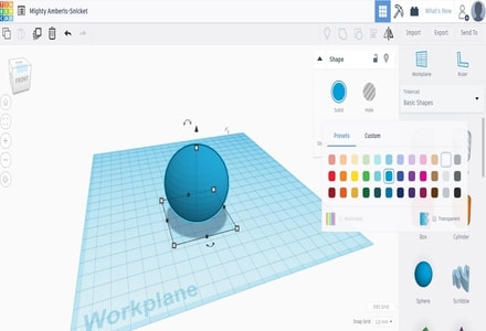
Then I have created another two spheres with smaller dimensions
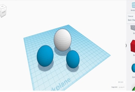
Then, I put the spheres on each others by place them on the center of the first sphere and pull the arrow up
.jpg)
Then, I have changed the color to white as well
.jpg)
Then, I have grouped the spheres togather
.jpg)
After that, I have added the snowman nose and eyes by adding the cone shape and cylinder
.jpg)
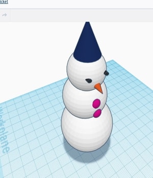
Then, I have added two buttons to it using half sphere shape
.jpg)
Finally, I have added his hat and the snowman is now complete!
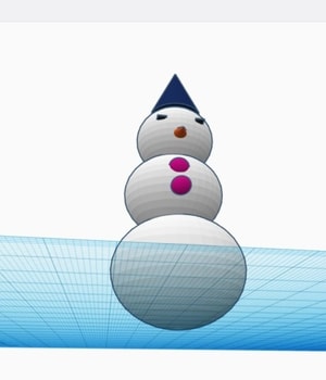
Finally, here is the orginal file
Blender
The final 3D software that I have worked with is Blender. I have visited their website and I was impressed by the 2D, 3D and animation pictures that I saw. Therefore, I decided to explore this software.
I have started by downlading the software for windows operating system. I clicked on the download button, and then clicked “next” on all the windows till I reached the “install” window. I clicked install and wait for the process to be complete.
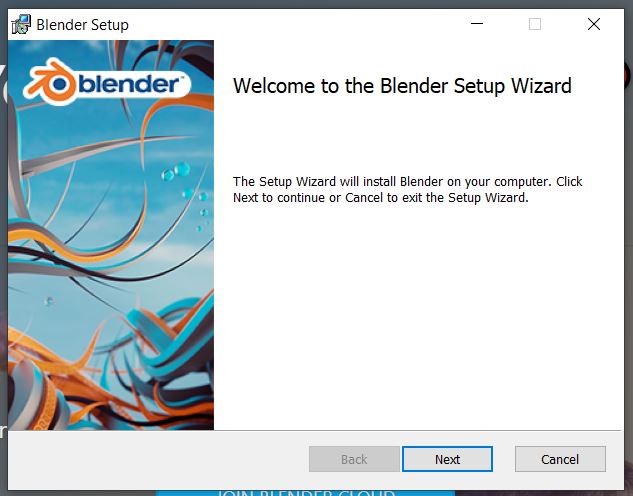
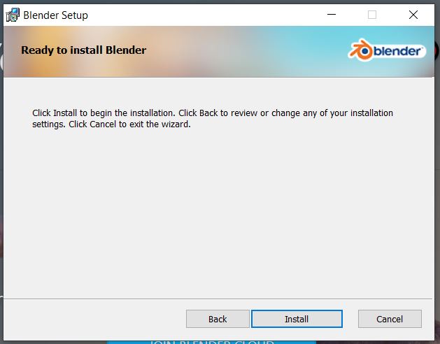
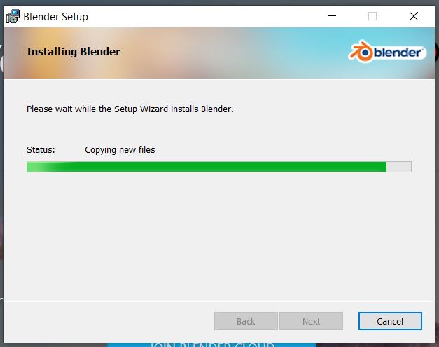
The software has been installed on my PC
And here is how the software looks like
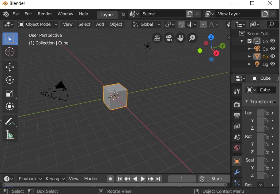
Since I am new to Blender, I decided to follow this video and build/create a doughnut! Here is some useful information I learnt through this video:
- To select an object - Right click.
- To rotate an object - Press and hold the middle mouse button and move the mouse around.
- To pand the view around - Press and hold the shift key then press the middle mouse button.
- To zoom in and out - Use scroll wheel of the mouse.
- To add part - Press Shift + A.
Now to create the doughnut in blender, here are the steps that I have followed:
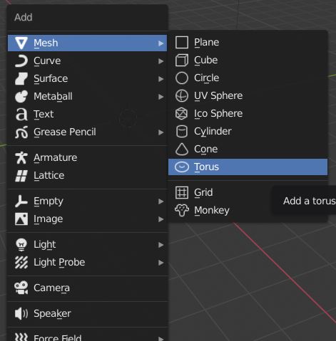
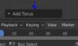
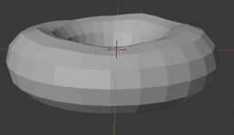
1- First, I have deleted the cube object and place a cylinder by clicking on Add > Mesh > Torus.
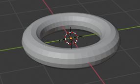
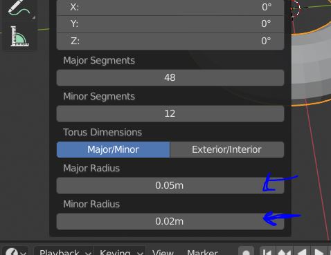
2- Then, I have edited the size of the torus to look more like the real world doughnut.
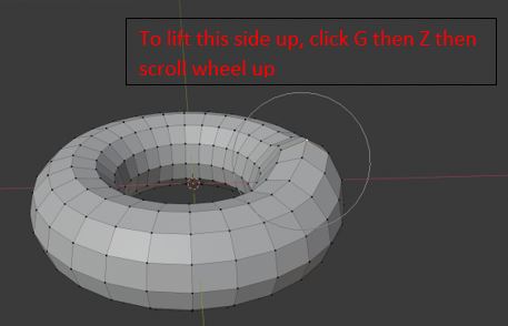
3- Then, I clicked on “Tab” key on my keyboard to enter to the edit mode. Then, I pressed O to enable the proportional editing. Then, I have move the dots up and down to make the doughnut little lumpy because no doughnut is prefect in shape!
4- Going back to the object mode, The shape will look like this.
5- Keep making some parts up and some down to make the donunt looks squashy a little.
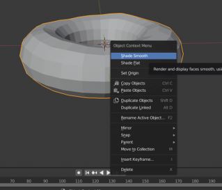
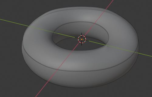
6- To make it look smooth. Right click, then “Shade smooth”
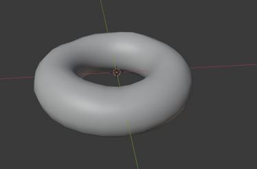
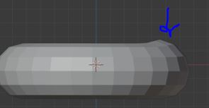
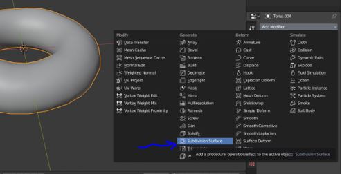
7- However, the edges still looks sharp. Therefore, enter to the spanner > add modifier > and chose the following modification tool “subdivision surface” which is very common to used in 3D software.
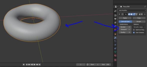
8- Enter the following settings and that’s what you will get.
9- After that, I have created the icing by duplicating part of a mesh then adding a solidify modifier.
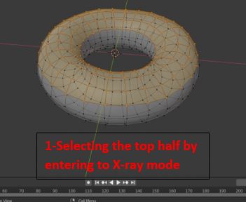
Next (Shift + D) to duplicate the part. It will be free movement. Press “Esc” from keyboard to fit it excatly on the top of the donut.
Next (P) and click on selection.
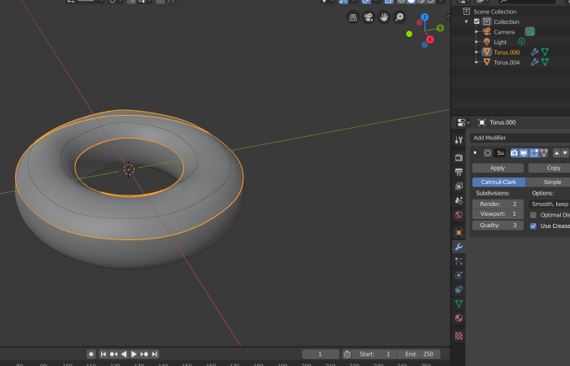
10- Then, go back to the object mode and you will notice that you have two parts now
11- Than, I have give thickness to the mesh (icing) by using the solidify modifier. Enter to the spanner > add modifier > General > solidify.
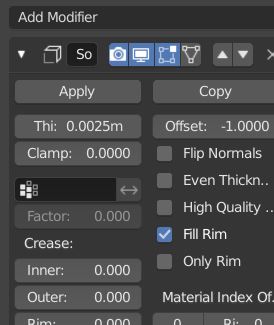
Note: Offset is 0.
12- Then, I have entered to the rendered mode by clicking on Z and chose “Rendered”
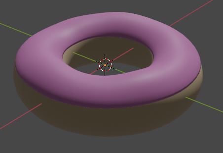
13- I have selected the icing layer and add material. In the material I have changed the base color to pink
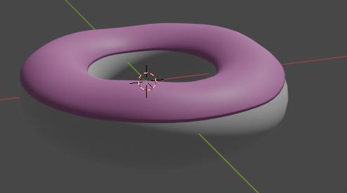
14- Finally, I have clicked on the donut layer > material > and changed the base color to brown.
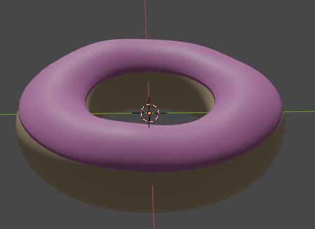
To download the design:
Please click here
In conculsion, I like blender, it’s incredible! Many greate things can be done in this software espacilly the things that are related to animation and visiual art. However, it is not easy software to be learnt for binngers. It need time and knowlage as it has a lot of editing and modification tool. On the other hand, Tinckercad is easy and very simple. It is limited in features and editing tool. I think it is very basic and suitable to be teach to kids as well. Fusion 360 is a good software as well and good to be introdunced for beginners. I like the experince with this software it is not very complicated and it gives users more space for editing and building staff.