14. Networking and communications
This Weeks’ Task:
Individual Assignment
- Design, build, and connect wired or wireless node(s) with network or bus addresses.
Group Assignment
- Send a message between two projects.
Group Assignment
Here is a link to the group assignment page.
Individual Assignment
Overview
In this week, I wanted to progress with my final project by connecting my input and output circuit together. For my final project, I will be having a circuit which has a thermistor and hall effects sensors in them, and the other circuit having a potentiometer, heating pad and 2 LEDs in it. The images below shows the two circuits that I will be using.
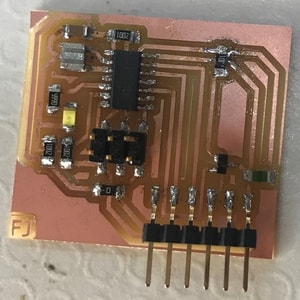
Input circuit, consists of thermistor and hall effect sensor. Detailed information about the input circuit can be found here.
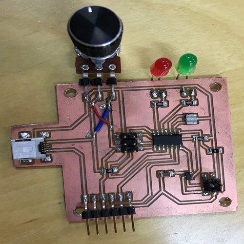
Output circuit, consists of potentiometer, heating pad (which will be connected to the 2x2 pin header) and 2 LEDS. Although the potentiometer is an input device, I have purposely placed it in the output circuit due to the design arrangement of my model. Detailed information about the output circuit can be found here.
The communication that I have in mind between the two circuits is as follow:
- User chooses a desired temperature by rotating the knob of the potentiometer.
- Thermistor will compare the desired temperature with the actual temperature.
- If the temperature is lower than the desired temperature, the heating pad will start to heat up and the red LED will turn on. This indicates that heating is taking place.
- Thermistor will continue to take readings every 5 seconds for instance. Once the desired temperature has been reached, the heating will stop, red LED will turn off and the green LED will turn on. This indicates that the desired temperature has been reached.
- Hall effect sensor can sense when the lid is closed and can initiate the thermistor to start taking readings and start the heating process. Once the lid is open, heating will stop.
In summary, the above points are going to be the scenario of my final project. There might be some slight changes occuring depending on the upcoming weeks while working on my final project.
Communicating
I wanted to do something less complicated than my final project communication, but, inlcudes most part of it. I researched and found a communication method that could help me do it. The communication method is i2c and I followed the steps written in this previous fabacademy student page to help me with the assignment.
Before starting, I had to download a library (attinycore) that supports the i2c communication using arduino ide. Here is the link of where I installed the library from.
This is how I connected my circuits together.
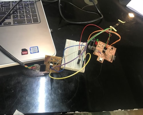
I used a breadboard to connect them using jumpers and FTDI cable connected to my laptop for powering purposes.
For the wiring connection, I exactly followed the above linked page. Here is a picture that shows the connection.
My master circuit was input circuit which sends the data and my slave circuit was the output circuit which receives data. I referred to the code written in the above mentioned page and edited it according to my needs.
I did a simple test just to check whether the circuits are able to communicate together. The code is just if the potentiometer from the output circuit reads the value 1, the LED in the input circuit will turn on, otherwise, it will be off.
Here is the code example for input circuit, which is the master.
#include <Wire.h>
#include <SoftwareSerial.h>
#define RX PA1
#define TX PA0
SoftwareSerial mySerial(RX, TX);

void setup() {
  mySerial.begin(9600);
Wire.begin();
}

void loop() {

Wire.beginTransmission(8);
Wire.write(1);
mySerial.print (1);
delay (1000);

}
Here is the code example for output circuit, which is the slave.
#include <Wire.h>
#include <SoftwareSerial.h>
#define led PA7

void setup() {
Wire.begin(8);
Wire.onReceive(receiveEvent);
pinMode(led, OUTPUT);
}
void loop() {
delay(100);
}
void receiveEvent(int howMany) {
int x = Wire.read();
if (x == 1)
{
digitalWrite(led, HIGH);
}
if (x == 0)
{
digitalWrite(led, LOW);
}
}
Unfortunately, I tried a couple of times to debug but this didnot work.
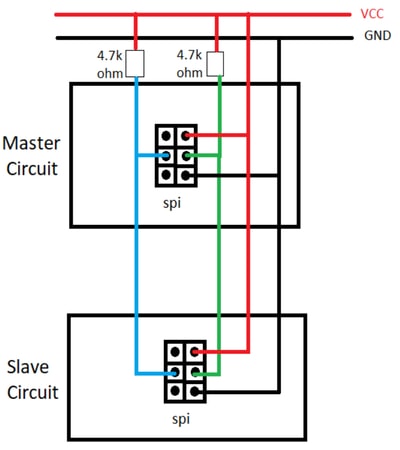
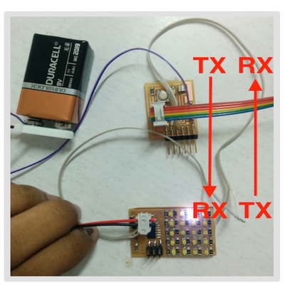
I then researched for serial communication between two attiny boards and I came across this page which helped me to do it. I again followed the instructions written on that page for connecting the wires and below is an image that helped me alot while connecting.
I followed the code written on that page and edited it according to how I want my communicatio to be. So what the code does is that if the potentiometer (output circuit) reads a value of 500 or greater
- It will show the number 1 in the serial monitor
- Red LED (output ciruit) will turn on and white LED (input circuit) will turn on.
Otherwise, if the potentiometer reads a value of less than 500, the green LED will only turn on.
I did this because I wanted to do something similar to my final project communication scenario, thats why I tested out with simple example.
Here is the code example for output circuit
#include <SoftwareSerial.h>
int v;
#define RX PA1
#define TX PA0
int potentiometerPin = 0;
SoftwareSerial mySerial(RX,TX); // RX, TX

void setup() {
  mySerial.begin(9600);
  pinMode(PA7,OUTPUT); // red led
  pinMode(8,OUTPUT); // green led
  pinMode(PA2, INPUT); // potentiometer pin
  }

void loop() {
potentiometerPin = analogRead(PA2);
if (potentiometerPin >= 500){
mySerial.println("1");
digitalWrite(PA7, HIGH);
digitalWrite(8, LOW);
delay(500);
}
else{
mySerial.println("2");
digitalWrite(8, HIGH);
digitalWrite(PA7, LOW);
delay(500);
}
}
Here is the code example for input circuit
#include <SoftwareSerial.h>
SoftwareSerial mySerial(PA1,PA0); //RX, TX
int v;

void setup() {
  mySerial.begin(9600);
  pinMode(8, OUTPUT); // white led
}

void loop() {
  v = mySerial.read();
  if(v == '1')
{
  digitalWrite(8,HIGH);
  }

else if(v == '2')
{
  digitalWrite(8,LOW);
 }
  //delay(200);
  }
Here is a video of the circuit showing how it worked.