16. Interface and application programming
This Weeks’ task:
Group Assignment
- Compare as many tool options as possible.
Individual Assignment
- Write an application that interfaces a user with an input &/or output device that you made.
Group Assignment
Here is a link to the group assignment page.
Individual Assignment
In this week, I designed an interface which enables the user to view and comprehend what is happening inside the circuit. I researched about simple interesting projects that i could do in the interface week and I found later that LED lights can be doubled as light sensors. So I aimed to create a simple and interesting project to show the responsive quality of LED to light. Since I had the LED in my echo hello world board, I decided to test it and see what happens. Details aboout the echo hello world board can be found in this page.
I used processing as my software to design the interface. The LED was treated as a light sensor hence acted as an input object. It began reading data via the analogue to digital convertor function and displayed the values on a screen which helped me determine how well it is responding to light.
This is the code that I used in arduino ide and displayed the values in the serial monitor to see how it reacts with light.
#include <SoftwareSerial.h>
#define RX PA1
#define TX PA0
SoftwareSerial mySerial(RX, TX);
int sensePin = PA3; //attiny led pin
int sensorInput; //The variable we will use to store the sensor input
void setup() {

mySerial.begin(9600);
pinMode (sensePin, INPUT);
}
void loop() {
// put your main code here, to run repeatedly:
sensorInput = analogRead(sensePin); //read the analog sensor and store it
mySerial.println(sensorInput);
delay(1000); // remove delay when inserting the code in processing
}
The video below shows the values I got from the serial monitor.
The image below shows the maximum and minium values that I received when I move the torch closer and away from the LED.
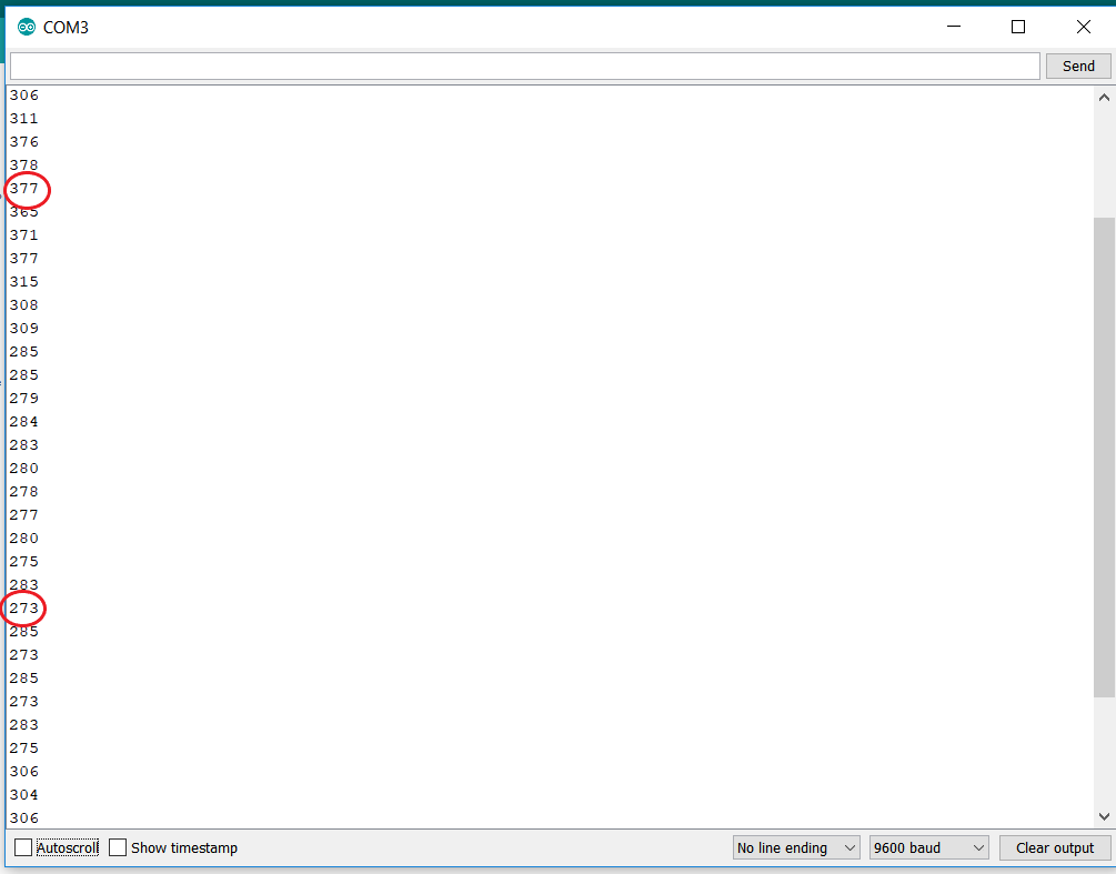
377-378 is the maximum value I got when I bring the torch directly on the LED.
273 is the minimum value I got which is when I cover the circuit with my hand and it experiences complete darkness
The rest of the values are when it transitions from dark to light.
I then wanted to do something that the user will be able to see graphically. Therefore, I thought of doing an interface in the processing software to represent what is happening.
I simply did a circle that changes in size as the light changes. So the arduino code will run and send the data to the LED serially, and then the code used in processing software will read it as a string, convert it to integer and maps that data from 0 to 850 instead of keeping it in the range of 250 to 400.
This is the code used in processing
import processing.serial.*;
Serial myPort; // Create object from Serial class
String val;
int y=0; //giving y an initial value
void setup(){
String portName = Serial.list()[0]; //0 is my port
myPort = new Serial(this, portName, 9600);
size(1000,1000); //screen size
}
void draw(){
while (myPort.available() > 0) {
val = myPort.readStringUntil(13); //until the line break (13 in asccii)
if (val != null) { //if its recieving a value
try {
y =Integer.parseInt(val.trim()); //string to integer
println(val); //printing to verify
println("val");
println(y);
} catch (NumberFormatException npe){
// Not an integer so disregard it
}
}
}
//println("val");
background(0); //black
float m = map(y , 250, 400, 0, 850); /* my led values range from 250 to 400
which I know by testing different light intensities.
I'm mapping those values from 0 to 850 to represent them visually */
ellipse(500, 500 , m , m); /*placing the circuit in the center of my screen
at (500,500) and giving it the size based on my light value */
}
Here is a video showing how it represented visually.