This Week's Assignment
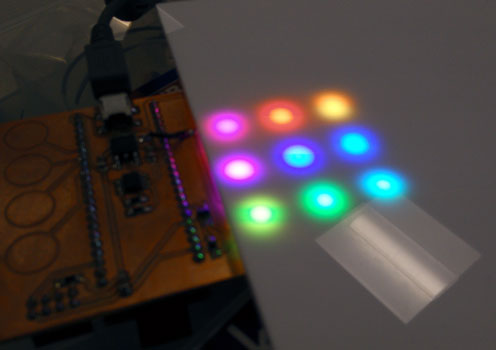
The assignment for this week was to read a microcontroller data sheet and program our board from last week to do something, using as many different programming languages and environments as possible. Here's the final outcome:

Notice that I'm using a new breakout board/shield I designed. You can read all about that in the post Bonus Content! Week 7.5: Designing a PSoC 4 Breakout Board.
Picking A Microcontroller
I already programmed last weeks board to cycle the LED colour, so I thought I would try something new this week instead...
Since I have a background in electronics, I've worked with a whole bunch of microcontrollers in the past. From what I remember, I've used:
- Microchip PICs - specifically their 8-bit PIC18F family.
- Renesas M16C - I wrote a 300 line assembler VGA driver that's probably some of the most elegant code I have ever written.
- Arduino - very useful due to the massive community. I tend to Arduino for super quick one off projects and for getting up and running fast with new peripherals (because there's usually already a library available).
- TI TMS320C6713 - technically a DSP rather than a microcontroller. The DSK6713 development board was probably one of the worst dev kits I have ever had the misfortune to use.
- Freescale KL26Z - The FRDM line of development boards from Freescale are really cheap and interesting. This board was my first dabble into ARM Cortex M0 programming. It's a different kettle of fish than 8-bit microcontrollers!
Along with the hardware, I've tried all the various vendor IDEs that go with them. In general, any that are based on Eclipse tend to be OK by me.
So what to do this week? Well I've been itching to try the Cypress PSoC 4 for a while now, so this seemed like an excellent opportunity!
Why PSoC 4?
The PSoC 4 (Programmable System on Chip) is packed with some really neat features that I wanted to try:
- It's based on the ARM Cortex M0
- Has programmable analogue e.g. opamps and comparators
- Has programmable digital (UDBs - Universal Digital Blocks)
- Has built in capacitive sensing
It's the UDBs that grabbed my attention most. They're kind of like having a tiny CPLD or FPGA built right into the microcontroller. You can even program them in Verilog. I don't tend to work with many analogue signals but the "programmable" analogue is pretty intriguing too!
I recently bought a CY8CKIT-042-BLE Bluetooth Low Energy (BLE) Pioneer Kit (to try PSoC and Bluetooth LE with debugging capabilities), but it's not part of the current Fab Lab Inventory. I also have one of the super cheap PSoC 4 CY8CKIT-049 4200 prototyping kits. Since it is part of the standard inventory, I decided I would start with it. Although it doesn't have debugging capabilities, I figured if I got stuck I could hack the debugger from the BLE kit and use that.

The kit itself is pretty sparse (basically it has an LED and a button), so I designed a breakout board/shield with some more interesting bits and bobs on it to play with. You can read about the design of the board in the separate post here.
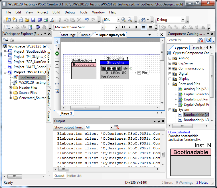
Controlling WS2812 LEDs with PSoC 4
PSoC Creator has two distinct sections for projects: a hardware section and a software section.
Hardware
To drive the LEDs, I used the hardware UDBs. The component came from Project #100 - PSoC 4 Times Square LED Billboard which was part of the PSoC 4 100 Projects in 100 Days event on Element14.

The component is a little bloated for what I need. I'm only driving 9 LEDs from once pin, not trying to draw pictures on a massive display board like in the project! Since I have plenty of flash and RAM on the PSoC 4, I didn't bother trying to strip it down. I imagine many of the unused functions get optimised out by the compiler anyway. I'm tempted to change a few things in the component myself at a later date e.g. use a colour order of RGB instead of the very unintuitive BRG!
Software
The software side of this test project is quite simple. Here's the main loop:
int main()
{
    StripLights_1_Start();
    StripLights_1_Dim(2); // Dim to 25%
    CyGlobalIntEnable;

    uint8_t counter = 0;
    for(;;)
    {
        // Set the colour of each pixel so that between them all, the entire
        // spectrum of the rainbow is displayed
        uint32_t pixelNumber;
        for(pixelNumber = 0; pixelNumber < NUMPIXELS; pixelNumber++){
            StripLights_1_Pixel(
                pixelNumber,
                0,
                Wheel(counter + (pixelNumber * COLOURSTEPSIZE)));
        }
        counter++;
        while( StripLights_1_Ready() == 0);
        StripLights_1_Trigger(1);
        CyDelay(10);
    }
    return 0;
}
The basic flow/pseudocode of the code is:
- Initialise the WS2812 component
- Loop forever
- Set each pixel to a colour so that all pixel colours are equally spaced on the colour wheel
- Set a new start colour
- Update the LEDs
- Delay to control update speed.
The Wheel() function is my adaptation of the equivalent function from the Adafruit NeoPixel Library striptest example. It simply maps a value of 0 to 255 to a colour on the colour wheel. It's perfect for making pretty rainbow patterns!
// Adapted from the NeoPixel library from Adafruit.
// Input a value 0 to 255 to get a color value.
// The colours are a transition r - g - b - back to r.
// Order seems to be BRG for the WS2812 driver
uint32_t Wheel(uint8_t WheelPos) {
    WheelPos = 255 - WheelPos;
    uint8_t R,G,B;
    if(WheelPos < 85) {
        R = 255 - WheelPos * 3l;
        G = 0;
        B = WheelPos * 3;
        return (B<<16) | (R<<8) | G;
    }
    else if(WheelPos < 170) {
        WheelPos -= 85;
        R = 0;
        G = WheelPos * 3;
        B = 255 - WheelPos * 3;
        return (B<<16) | (R<<8) | G;
    }
    else {
        WheelPos -= 170;
        R = WheelPos * 3;
        G = 255 - WheelPos * 3;
        B = 0;
        return (B<<16) | (R<<8) | G;
    }
}
My changes were quite superficial. I increased the readability and swapped the colour return order to BRG to match the hardware component.
And that's it! The result is a pretty rainbow pattern on the LEDs. Getting a picture of them is pretty hard. This picture was taken in a fully lit lab, with the LEDs at 25% brightness and with a diffuser to help reduce the brightness

Get The Files
As usual, there are two places to get the files:
- Here is an example PSoC Creator project to make the LEDs flash a pretty rainbow pattern. These files are probably out of date and are only here to be "in the archive".
- On my GitHub. These will be the most up to date. Get this one.
Comments
comments powered by Disqus