This Week's Assignment
The assignment for this week was to take the echo hello-world board, add an LED and a button, verify the design and then make it.
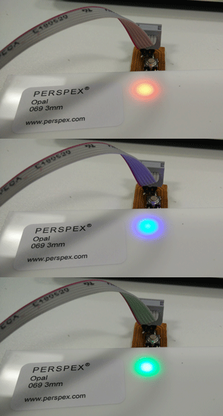
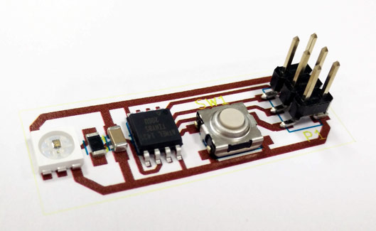
I thought that was a bit boring so decided to make my own board instead. The idea was to make a board to test the WS2812 LEDs that I'll be using in the clock/catan table. I loosely based the design around the FabTiny*. This is the final outcome:
A New PCB Engraver
We have a new toy at Fab Lab Strathclyde. It's a Denford PCB Engraver.
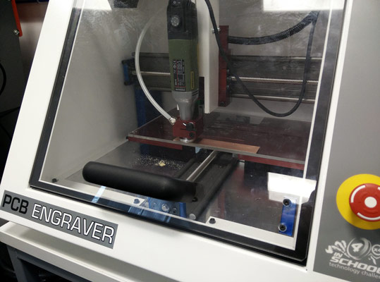
The machine has some pretty nice features:
-
The best feature of the machine is that it has a floating head. That means that the copper board doesn't have to be totally level. Instead, the drill depth is set by adjusting the floating head and the pad around the drill bit "floats" over the board to give a constant depth of cut.
-
It's a lot faster than the Modela.
-
The spindle can do 20k RPM (as opposed to the 6.5k of the Modela).
-
It has a range of collet sizes, so it's much easier to find mill bits for. I used a 0.4mm end mill for all the circuits in this write up.
-
It comes with software that take in gerber files directly and spits out a compatible CNC file. No more PNGs!
Before making any circuits with the Denford, I ran some simple tests to find the best settings.
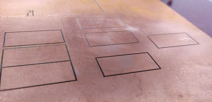
I did a comparison between feed rate, spindle RPM and depth of cut. With the depth set to just cut through the copper and no more, the best RPM was in the 16k to 20k range when combined with a feed rate of about 15%. Although some of the squares cut great with feed rates up to 35%, I found that more complex circuits produced a better result when slowed down. 20% was OK, but 10% would be best for really complex PCBs. Somewhere around 15% gives a good starting point to refine from. I actually think the main limitation was the double sided tape I used to stick the boards down. If the tape was stronger, faster rates would be possible.
Helping Out A Friend
Coincidentally, a mechanical engineering friend of mine needed some help making a little PCB to combine an XBee with a GPS modules. Since it was a super simple design (two through hole modules and a 5V to 3.3V regulator), I put it together quickly in KiCad and used it to test the Denford on a real circuit. The results were pretty good.
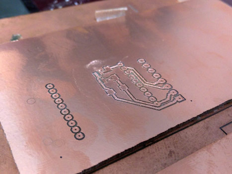
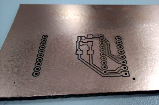
The only trouble I had was passing a KiCad drill file to the Denford software. For some reason the Denford software seems to expect the drill file to be in a non-standard Excellon format. However, a bit of playing with the raw files and I managed to convert the KiCad .drl file into something the Denford would accept. This won't be much of an issue for Fab Academy, as basically all of the boards are surface mount anyway.
Getting To Grips With KiCad
To design the board, I decided to use KiCad. I went with KiCad over Eagle(http://www.cadsoftusa.com/) because a) it's open source and b) it doesn't have any limitations on board size. With the floating head on the Denford, it should be possible to engrave some really large boards without worrying about how flat the copper is.
In order to take full advantage of all the latest features in KiCad (such as shove routing - thanks CERN!), I built the latest dev release from source using the handy script on the KiCad website. The install wasn't totally without issue (for some reason on Mint 17.1, some of the dependencies were missing, but I just installed them manually) but I got through it easily enough.
There are definitely a lot of features missing in KiCad, and the user interface is pretty unintuitive. Some of the things I didn't like:
-
Wiring a component in the schematic and then moving it is a mess. I'm used to the wire handling of something like Simulink, and KiCad is rubbish in comparison.
-
A lot of the documentation and tutorials are for the old "stable" release. In a toss up between support and new features, I went with new features.
-
The user interface is so unintuitive that I found myself having to seek help for basically every single thing I needed to do.
-
The footprint editor is barebones at best. In fact, all of the drawing tools are pretty shocking.
-
PCBnew (the layout part) seems to have different rendering modes, and the functionality between them is completely different. For example, you have to go into OpenGL mode to use the shove routing feature, but in that mode I found that the ratsnest didn't work...
-
The newer dev releases use a new format for footprints and schematic libraries and it's a bit all over the place right now.
To top it all off, the Fab Library for Eagle isn't 100% compatible. I found I could automatically convert most of the schematic symbols but the footprints failed pretty miserably. Instead, I've just been doing my own footprints for parts as I need them.
OK, rant over. I'm at the stage with KiCad now that I can be productive, but it really is a fickle beast you need to learn to tame. To be fair, my past experience with Eagle wasn't much better. I feel like a lot of the "current" PCB software is stuck in the 90s somewhere...
Designing A WS2812 Test Board
The schematic for the board is nothing fancy.

If you're not familiar with the WS2812 LEDs, they're a really cool little device. Each LED has it's own built in control circuit, and you can chain multiple LEDs together. You send 24-bits of RGB data to the chip, and it does all the PWM to give you the color you want. So, from one microcontroller pin, you can control THOUSANDS of RGB LEDs individually. Pretty cool.
Technically each WS2812 is supposed to have it's own 0.1uF decoupling capacitor, but for a single LED and such a small board, I just used one capacitor for both the tiny85 and the LED.
(On a side note, the only reason I'm using the 6-pin WS2812S and not the better 4-pin WS2812B is that I got sent them by mistake in an order and got to keep them, so I have a hundred of them to use up!)
I then made/found footprints for all the components, and exported the netlist to PCBnew to layout the board. This is my final layout. You can see the influence of the FabTiny*.
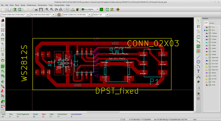
Since I had made a lot of the footprints myself, I first printed the board out to scale and placed the components on it.
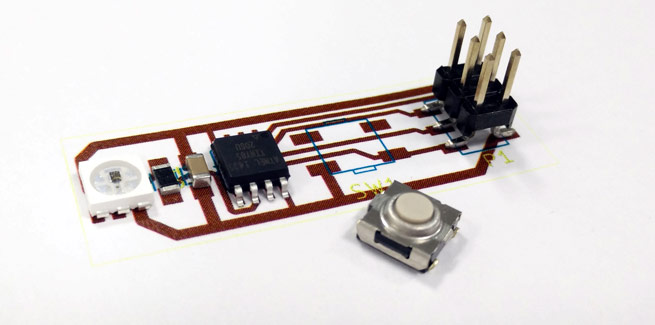
It was a good thing I did too. I had accidentally managed to assign the wrong pin numbers to the footprint for my button. I fixed the mistake (and made the board a bit smaller in the process) and printed it out again for a final check.
Cutting The Board
I exported the gerber and brought it into the Denford software. Even though my board passed a design rule check for a clearance of 0.4mm, the Denford software complained it wouldn't be able to isolate all of the traces (probably due to some tiny mismatch in segmentation). Unhelpfully, it doesn't tell you where. You have to scroll around looking for the problem.
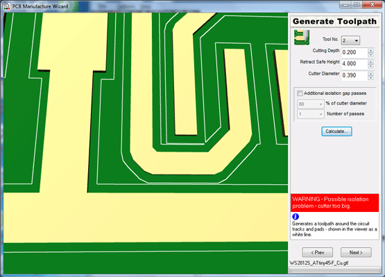
Although the board would probably have been fine, I adjusted the problem parts and regenerated the gerber. I then sent a few boards to the machine with different settings, but in the end all of them would have been usable. Each board took between 5 and 15 minutes depending on the feed rate.
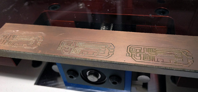
For such a simple circuit outline, it was much quicker to just cut each board out with a band saw. Some light sanding and a wash later, and it was time to solder a board.
Another New Toy
I lied when I said we got a new toy. We actually got two: the Denford engraver, and a cheapo Chinese reflow oven. I tried applying the solder paste straight from the fridge using the plastic nozzle it came with, and ended up with a bit of a mess.
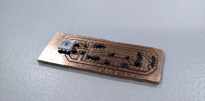
For a future week, I'll try laser cutting a solder paste mask from kapton tape. However, for this week I just went ahead and added the components.
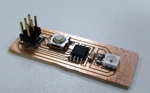
Then it was off into the reflow oven using a profile matched to the paste I was using.
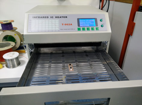
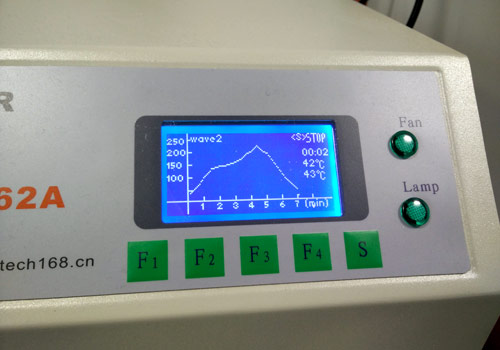
On the first reflow attempt, not all of the paste reflowed successfully (probably due to me having way too much on). You can clearly see the paste around the LED hasn't gone nice and shiny.
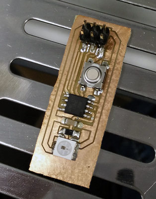
I took the easy option and just put the whole lot back in for another bake. A bit risky given how temperamental the WS2812s can be with heat, but I had plenty more if I needed a replacement. All of the paste reflowed after a second bake, but my ham fisted application of the paste had resulted in a few solder bridges on the ATtiny and the LED. They were easy to fix with a soldering iron and some wick though.
Board soldered, it was time to try programming it.
Programming The ATtiny85.
To program the board, I decided to flash the Arduino bootloader. The main reason was it meant I could use the Adafruit NeoPixel Library to talk to the WS2812 without writing my own driver.
To add the ATtiny85 as an option in the Arduino IDE I used the arduino-tiny core and used a FabISP to flash the 16MHz internal PLL bootloader. I also had to set some extra udev rules since I'm using Linux Mint. AS220 has a tutorial that's dead easy to follow if you're running an Ubuntu based distro too.
Bootloader flashed, I loaded the basic example from the NeoPixel library. The only changes I made were to the number of LEDs (to 1, obviously) and to the pin the WS2812 was on (it's on pin 2 of the tiny85, but thats actually called pin 3 in the Arduino IDE). I uploaded the sketch and...
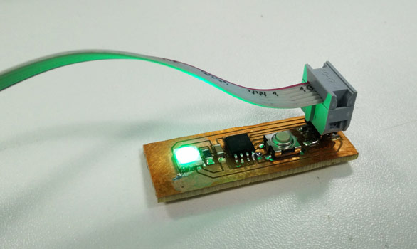
Success! The LED lit up green. Some simple tweaks to the sketch and I had it flashing RGB.

My plan for the board is to use it to test out some different samples that Perspex kindly sent me for free. They have a wide range of different acrylics specifically designed for diffusing LEDs, and I need to find the perfect one for making the Catan table. The WS2812s will need the extra diffusion. These guys are bright when on full power! My camera really struggled to capture them, even with a really strong diffuser layer in front.
Get The Files
For a change, the files are nice and small this week. You can download them directly from here: WS2812S_ATtiny45.zip.
However, as always, the most up to date files can be found on my github.
Comments
comments powered by Disqus