This Week's Assignment
The assignment for this week was to make a press-fit construction kit. "Press-fit" means that the pieces slot together snugly and hold the parts in place by friction alone.
As well as a press-fit kit of parts that can be put together in different ways, I also cut a press-fit cardboard version of the word clock I modeled in Week 2: Computer Aided Design.
Although not directly part of the assignment, I also followed Neil's advice and gave the Roland vinyl cutter a whirl.
The press-fit clock and vinyl cutting can be found in my bonus post: Bonus Content! Week 3.5: Even More Computer Controlled Cutting.
Press-fit Construction Kit
There were three main steps in making the press-fit construction kit:
-
Determine the perfect slot width for a good press-fit
-
Design and cut the parts
-
Play with it!
Finding The Perfect Fit
The first step to getting the prefect fit was to measure the lasers kerf. "Kerf" means the width of material burned away by the laser. To get a rough idea of the kerf, I cut out a rectangle split into 5 sections all 10mm square. With our 40W Epilog laser cutter, I found that a vector cut at 30/100/auto (thats 30% speed, 100% power and automatic frequency selection) gave good reliable cuts. I was surprised that the cardboard needed basically the same settings as I've previously used for 3mm plywood!
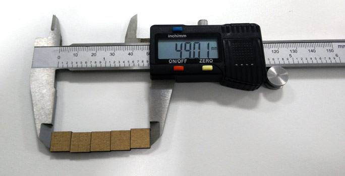
If the laser kerf had been zero, you would expect that measuring all 5 squares would come to exactly 50mm. With 5 squares there are the equivalent of 6 laser widths of material missing (the middle cuts, plus half a width at each end). Doing some quick maths:
I decided that since the cardboard was a bit forgiving and would compress, I would round this to 0.2mm. That means reducing slot widths by 0.2mm, or equivalently doing an offset on the entire part outline of 0.1mm.
Following previous student Anna Niespielak's example, I made a pair of slot rulers for testing the fit.
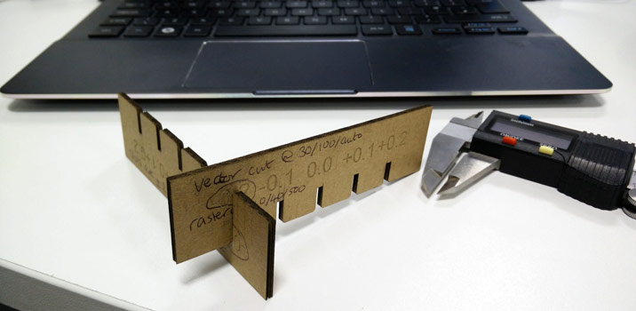
I found that reducing the slot width by 0.1mm gave a good, but not perfect fit. As expected, the -0.2mm slots gave a nice snug fit. The perfect fit was probably somewhere in between, but I went for the tighter fit. As a compromise, I went for slots that were 0.15mm smaller, but also added tiny little nodules of 0.025mm on each side of the slot. I figured this would give a tight fit, but also allow for some variations in the thickness of the cardboard.
Designing The Parts
I used Inventor to make the parts, since I'm starting to know just enough about it to be dangerous. I decided to go for a hexagon base part, with some straight and curved connectors. Why hexagons? Because I thought I might as well stick with the Catan theme. The hexagon acts as the master, and the other parts update based on its parameters. The size of the hexagon, the slot depths and (of course) the kerf are all parameterised.
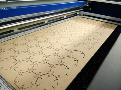
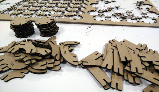
I cut out a few of each part to verify my design, then cut out a whole sheet of them. A 600 x 300mm sheet took just over 14 minutes to cut, and then another 5 to get all the parts out.
Play!
I hadn't really expected to have so much fun with the kit. Instead of doing my documentation, I got distracted for well over an hour just making different shapes:
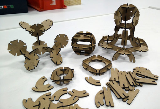
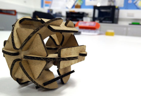
My favourite shape was the ball:
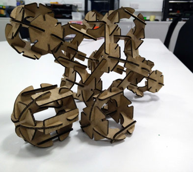
Eventually I settled on keeping the parts in these configurations:
The Good, The Bad And The Dirty
Overall I was really impressed with the cardboard. I thought it was going to be rubbish but I can see why Neil was keen for us to give it a try. It's super cheap too, and I can see myself proofing most of my designs in cardboard in the future.
I was pretty happy with the fit I achieved.
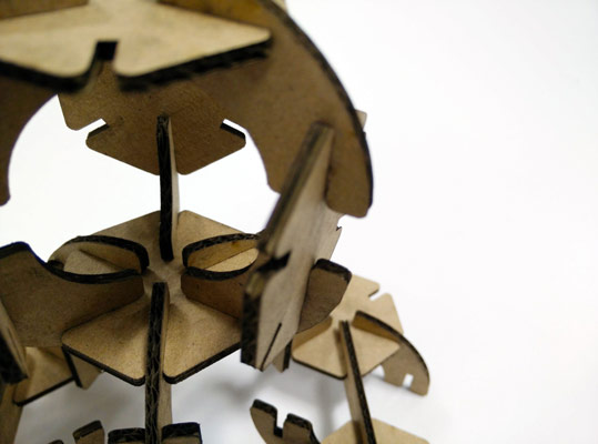
However, in hindsight, I probably would have been better using the -0.1mm slots, or not bothering to add the nodules to the inside of the slots. For slotting single pieces together the fit was excellent, but when it became time to slot multiple pieces together in 3D shapes the fit was tight enough that some of the parts didn't survive being taken apart again.
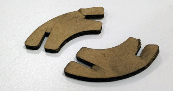
I also realised the parts were a bit more flexible in how they could be put together, as the slots were good for fitting straight onto solid edges too.
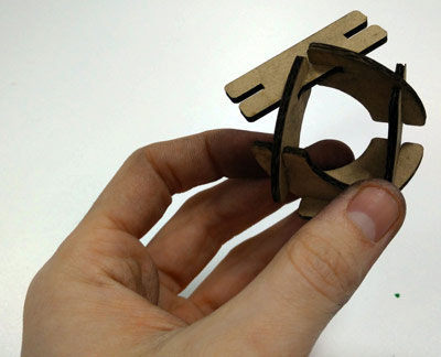
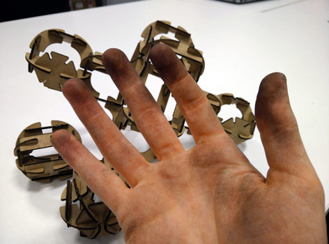
The big downside to cutting cardboard with a laser? Carbon. EVERYWHERE
Get The Files
As seems to be becoming the norm, file sizes limit what I can add here directly, so you can get all the files on my GitHub.
To keep with the spirit of the archive:
- Here is the press-fit ruler (note that I added the raster labels in CorelDRAW, but they go from left-to-right -0.2 to +0.2mm in 0.1mm increments, as in the picture above)
- Here is the component press-fit parts
Both are designed to be cut from 2.5mm cardboard, and the parts use the -0.2mm slot width I've talked about above. Happy press-fitting!
Comments
comments powered by Disqus