UPDATED 2015-18-04: I've added a section at the end covering the fully parameterised version of the clock model.
This Week's Assignment
The assignment for this week was to model a possible final project. The term "model" is used pretty loosely, meaning draw, render, animate, simulate or pretty much any computer aided design (CAD) method to represent the project.
As I mention in my Final Project Proposal page, I've already made V1.0 of a word clock. The files for V1.0 are available on my GitHub.
The original model was made in Autodesk Inventor, which is available for free to students.
The face of each part was then exported as a DWG file and imported into CorelDRAW X6 for layout and adding the lettering, before being cut on the Epilog laser cutter.
This weeks plan is to improve my existing Inventor model and, if I have time, I'd like to give OpenSCAD a try too.
So What Needs Fixed?
There were a couple of issue with the original model/design:
-
Parameterisation: Although I tried to parameterise as much of the model as possible, the only parameter that worked consistently was being able to change the thickness of the plywood. Ideally, I would have liked to be able to parameterise a lot more. For example the number, size and spacing of tabs, or the number of letter positions. The most essential parameter I wanted to be able to control was...
-
Kerf: I didn't manage to make kerf a parameter, and in the end I just ignored kerf entirely. I used wood glue to join the grid pieces and the outer frame parts. In actual fact this worked out for the best. Because this essentially slightly compressed the overall size of the outer frame, the front and back plates did become snap-fit. I had been worried I was going to have to use some kind of hinge to keep the front and back plates removable. Isn't it a nice when things accidentally work out for the better?! That being said, if I swapped to something like acrylic this might not be the case. Parameterised kerf would keep the design nice and flexible.
-
The Back Plate: There were two problems with the back plate. The first is that I forgot to add a hole for putting in a power socket. The second was that I neglected just how much heat the LEDs would generate. With nowhere for the heat to escape, it started to melt up the glue I had used to secure the LEDs in place. Both of these problems were sorted by adding the appropriate holes using a drill, but since I'm updating the design anyway I want a more elegant solution.
-
Securing the LEDs: I tried two different ways of attaching the LED strips to the interior plate. The first port of call was to use what most engineers reach for when something needs to be stuck in place: duct tape. Unfortunately, the cheap stuff I had didn't stick very well to the plywood, and the heat from the LEDs was also causing problems. My second port of call was to use what most hobby craft people reach for when something needs to be stuck in place: hot glue.
As I mentioned above the heat from the LEDs was causing the glue to become malleable, resulting in the LED strips being able to shift slightly. Glueing the strips down was also a bit too permanent for my liking. On top of that, as anyone who has ever used a glue gun will know, hot glue is excellent at getting on everything it's not supposed to and generally making a quite remarkable mess for such a small device.
-
The Middle Plate: The middle plate was OK. Or more precisely, it would have been OK if the LED strips had been consistent. The problem was that the LED strip I was using was actually a whole bunch of smaller strips soldered together. Although the LEDs were nominally 16.7 mm apart (60 LEDs per metre), the overlap between two soldered strips meant that this sometimes decreased by around 2 mm. That's not a lot, but it did mean that the LEDs didn't fit nicely into the grid holes. Instead, I had to de-solder the strips and add some ridiculously short pieces of wire to keep the LED spacing consistent. It worked, but it was pain and a waste of time. It would be much better to have a middle plate that accounted for this potential variance in LED spacing.
-
Mounting the Electronics: I never added any mounting points for the control electronics. The current version just has them sitting loose in the back. Not pretty, and not good for transport, as they could shake around and damage connections/components.
-
No Lettering: The letter cut outs were added post-model in CorelDRAW. This added an extra step to the process and therefore an extra potential point of screw up. Also, I want to get away from CorelDRAW, as we only have it installed on one machine in our lab. Porting the layout to Inkscape for cutting would be much better (and easier for other people to work with too).
That list kept getting longer and longer the more I thought about it... I think that's enough to be getting on with for now!
So How Far Did I Get...
Actually, not very far...
Surprise surprise, making a model that is completely parametric isn't exactly easy. After a lot of effort, I've managed to get as far as having the outer frame completely parameterised. I can control the overall dimensions, number of tabs, their size and their spacing (independently on each edge) and can take kerf into account for when it comes to laser cutting.
Here's the progress so far, using the same control dimensions as my V1.0 clock.

And here is a different box, using 6 mm ply instead of 3mm, with different overall dimensions and tab parameters on each edge.

I'm slowly getting the hang of what not to do when it comes to parameterising designs. For example, don't constrain new geometry on features that might not exist depending on your parameters... That one took me about two hours to fix. Urgh.... (And yes I am well aware that that sounds really obvious, but it's an easy mistake to make!)
The point I'm at as of the time of writing is tagged as v0.1 in my GitHub. I fully intend to get this whole damn clock paramterised. I'll add that future awesome version to the archive once it exists...
Update!
So I eventually managed to get most of the model parameterised! The base version of the clock can be completely controlled. The size, number of tabs, number of rows and columns of letters... Pretty much everything that I might want to change, can be.

There were some snags though...
-
The LED support structure was experimental, so I didn't try overly hard to parameterise it. As a result, there are two version of the model now.
- wordClock.ipt is the really parameterised version. The downside is that it lacks mounting holes for the electronics and doesn't include the LED strip supports. It also doesn't account for kerf directly.
- wordClock_NonParametric.ipt includes the LED support structure. It also has derived .ipt files for each part, and within each of those parts I've accounted for kerf. I've called it NonParametric but actually a large part of it is still parametric. It's just a lot more...flaky.
-
Inventor is rubbish when it comes to handling the extrusion of text. As a work around, I've marked the construction grid on the front face as exportable and it can be used to align text in Inkspace/CorelDRAW.
-
The .dwg files for laser cutting layout aren't the best. You can't seem to copy a view. You have to re-place the same part over and over. I'm not overly confident in directly sending the files to the laser cutter either, and on top of that I want people without AutoCAD/Inventor to be able to access the final version of files. Instead I've found it best to export the .dwg as PDFs that can be imported to Inkscape/CorelDRAW.
Let's look at the more interesting but less parameterised version in some more detail.
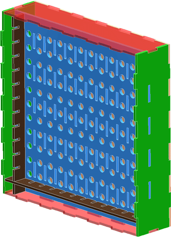
A More "Solid" Word Clock Model
By solid, I mean that its specs are more locked down. It's set to use 3mm plywood, be 216 x 216 x 60mm and have a character grid of 11 x 11. It's also got some experimental supports added for holding the LED strips in place.

The LED supports are essentially strips of ply that hold the LEDs in place, with the supports being held by some little clips. The clip mechanism looks like this:

Basically, the clip slots through, then rotates in the circular hole before being slid to the side to lock it snugly in place. My main concern with the design is that the support pieces will flex too much, and the LED strips in the middle of the clock won't be held tightly in place. If that is the case, I'll cut the supports out of 6mm ply instead. I'm also worried the clips might be a bit thin and prone to snapping. I can thicken them up if needed.
I've cut this version of the clock out in cardboard. You can read all about it in my Week 3: Computer Controlled Cutting post.
Get The Files
Inventor files are "large". The clock file is only 2MB, but that's large in relation to our limit of only using about 1MB per week for the archive...
To meet the requirement of having my files in the archive, I'm including the current version (at the time of writing) of the fully parametric model. You can download it here.
However, this version is almost certainly out of date. I would highly recommend you get the latest and greatest, as well as the solidified version of the clock, from my GitHub.
Comments
comments powered by Disqus