Project development
My notes :
20 march 2014 | first hinge concept test
As a first step for my project, I need to understand how to design a hinge with movement.
On the internet there are many (end result) examples to find relating this subject.
Like
https://www.youtube.com/watch?feature=player_embedded&v=EHwaQRyXG50
After consulting with my tutor I got the advise to not over complicate it, and start the understanding the basics.
And see what type of issue and/or limits come with it.
As a first test I made:
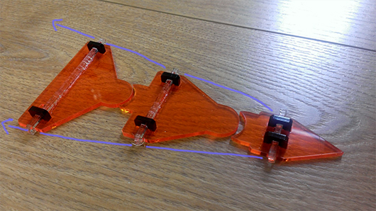
The idea is that every joint moves by pulling the wire connected to the tip of the tail.
By pulling, the tip of the tail will move first and the rest of the joints will follow.
Right now I'm pulling (of course) by hand, but later the idea is to let this work trough servo's.
The idea kinda works, but what I'm missing is the way to realign them.
Once they are pulled to either the left or right side, there is no way to get them back or in a other position.
24 march 2014 | Cardboard hinge
For this test, I adjusted the shapes I made for the press fit kit assignment ( from week 3 ). And cut it out in cardboard with the lasercutter.
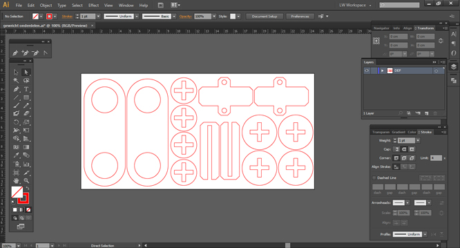
The design is a bit more complex. This time the joints are are stabilized by being connected trough each other.
Creating movement by pulling on the cords works fine. The alignment issue isn't solved, but works now because of gravity.
2 april 2014 | 3D printed joint
For mold & cast week I made a 3D joint design.
The casting process was quite difficult. Even after trying a few times I didn't manage to get one
good example without bubbles.
And, at the moment we only have the hydro stone and drystone cast material available for casting,
while I had more of a plastic whatnot in mind for my joint.
Since the model has been prepared in Rhino, I exported the file as a .stl to see how it would turn out as a
3D printed object.
(The Makerbot Replicator 2, printed in white PLA)
The printing time for one joint is 28 minutes. It needs no support or rafting structure, so the print turns out
really nice.
I did sanded it down a little bit, at the beginning and the end point of the round surfaces.
As you can see in the movie clip the rotation kinda works, but it does not respond as smooth as I would have hoped.
And a big issue; after moving a joint back and forth they don't re-align again.
Gravity this time won't work, because the whole structure is used to light.
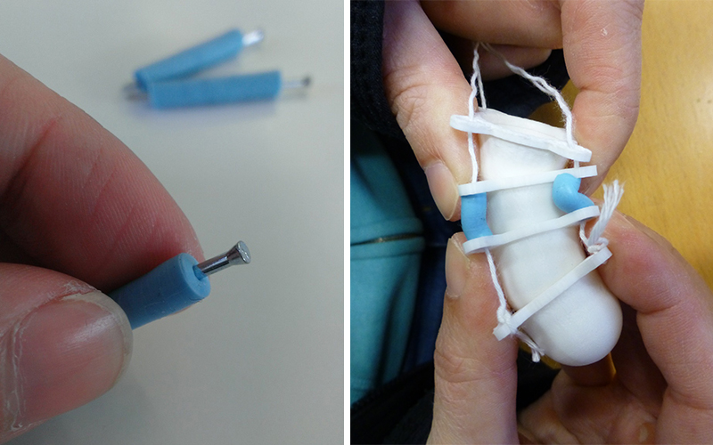
As a experiment I did cast little tubes of oomoo, to see if they could work as little springs.
I was hoping they could provide the stabalisation needed for alignment.
The cast turned out nice, but the oomoo is not a spingy enough material to prefom well for what I had in mind.
11 april 2014 | 3D printed joint - improved version
I did some more research on the internet and concluded that there are many solutions to creating movement.
(soft core centre or a 2 way bending hinge or ball joint etc.)
And every type of joint seems to come with it's own set of issues. Most types of joint's work well with only 2 or 3
bending points, but when using many (like in a tail)
they all seem to get the same alignment problem, and curling of the tip of the tail only problem,
and struggling against gravity.
A example that comes close to what I had in mind is: http://innerbreedfx.deviantart.com/gallery/39368026
A example of a nice but too heavy design (youtube clip is at the bottom of the page): http://forums.furaffinity.net/threads/125248-
Animatronic-Tail
For my design: I choose to improve the stability by replacing the cotton tread with metal wire.
And to keep the metal wire's in place at the tip of the tail, I used a terminal block (stripped of the plastic).
I also wanted to make the movement a bit bigger without adding more joints.
So I opted for laser cutting some press fit 'spacer' pieces out of acrylic to fit in between.
And the result is really nice. :)
21 april 2014 | building servo container
Now that I have a board to direct the servo's ( week 12 assignment ) what to do,
I need a container box for them as well.
Because for the servo's to function, the nee to be screwed down in to a plate (as anker/fixed position).
I haven't considered the final look of the box yet,
so for now a simple extension to the MDF cube
I already had made for the previous tail test will do.
Right now I'm testing with only 1 servo, the proper placement (design) of the second servo will come later.
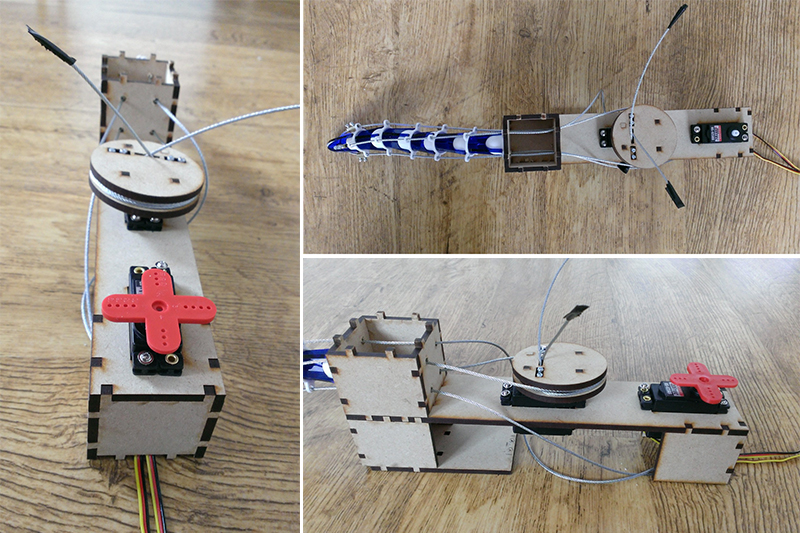
The important part of this servo box design is figuring out how to get the servo's to pull on the wire's.
If the metal wire's are tied directly to the small red cross of the servo,
the result movement will be tiny because of the small radius of the cross.
To enlarge movement a bigger radius is needed.
As simple small test to prove this; I tied a pencil to the cross of the servo,
and then tied the metal wire to the tip of the pencil.
and off course this works ... movement end result is bigger/better
So, I puzzled over a wheel design, making it as small as possible without losing the big movement.
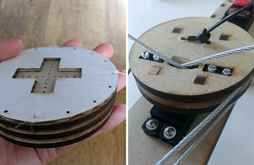
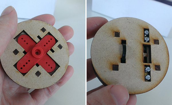
I made a press fit lasercut design, build up out of 3 Layer of 4mm thick MDF.
- The bottom layer has a slot for the red plastic sevo cross. A tiewrap prevents it from popping out.
- The second layer has slots for the wire to feed trough.
- The little metals with screws are slotted in from the top to keep the wires in place.
the new movement test: ( see also week 12 assignment )
5 may 2014 | improving mech design
For the mechanical design week assignment ( week 14 )
I re-designed the servo box, servo wheel & tail.
The end result is a way more fluent movement.
8 may 2014 | debugging electronics
Then the next step was getting the electronics finished.
I already started with setting up a network for the week 13 assignment.
The goal is to get my sensor board to communicate with my servo board trough a wired connection.
To debug my code I got some help for my tutor and lots of explanation on how to work with the logic analyzer & oscilloscope.
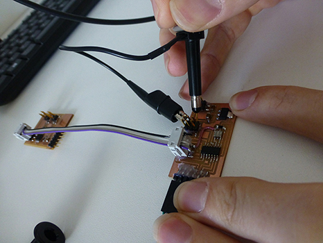
Now that my code works, it time to test the sensitivity of my sensors (
week 10 ) as you can see in the picture below.
(The red/yellow beams represent 3 interval moments of 1 sensor. Same for the blue/green ones).

And what know becomes very visible while testing is the impact of noise.
The more electrical devices (or people)
there are in the same room, the less response there is on the sensor.
After presenting this during class Neil gave the advise to try out a transmit/recieve sensor
as improvement for my final version of the dragons tail (transmit/receive picks up less noise).