wk12 | output devices
Assignment :
- add an output device to a microcontroller board you've designed and program it to do something
Download : .c servo code + eagle schematic & board
My notes :
17 april 2014 | Making the board
I'm interested in making servo's work, since I can use this for my
final project.
I started out with copying Neil's example board, and with the advise from my tutor I added in some small changes.
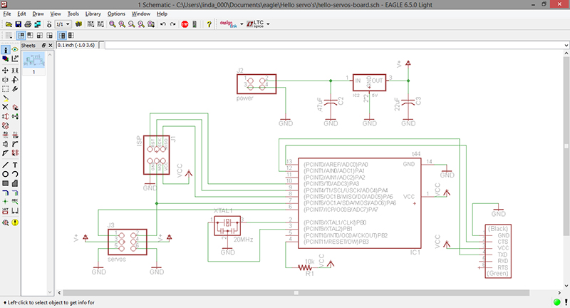
A problem I ran into was placing the regulator IC2 5V form from Neil's example board.
I couldn't find it in the Fab library, so I had to search in the Fab inventory to find the right product name.
IC REG LDO 5V 1A SOT223
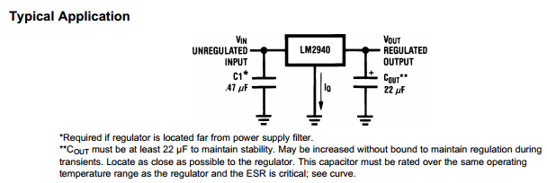
My tutor advised me to copy the design as shown in the datasheet. So that means adding C3 22uF in my schematic.
And since this part isn't in the fab.lbr, we also decided to add this one to it (also helps prevent a routing error later on).
And the 2 other changes added to the schematic was a extra 6pin header, and a extra vcc path.
These two changes will connect servo's > battery and the microcontroller > computer.
So I will be able to give input directly to the board (form my computer).
(And beware: a extra reason to add a second vcc;
the attiny will get damaged if connected to a turned off battery, yet does get inputs via the usb).
The routing and milling of the board were done without any problems.
But for the soldering: I needed a C3 22uF component. Which we don't have in the standard FabLab inventory.
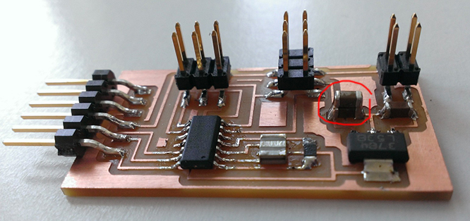
To solve this issue I learnt that it is also possible to solder to parts upon each other.
So get the 22uF I added two 10uF capacitators (stacked to put them in parallel).
Next step is executing the make file. For testing I used Neil's example code:
C (two-channel, software PWM) & makefile
But when setting the fuses I got this error:
avrdude: initialization failed, rc=-1
Double check connections and try again, or use -F to override this check.
avrdude done. Thank you.
make: *** [program-usbtiny-fuses] Error 1
It seems that my terminal does talk to my programmer, but not to the new board.
After further inspection I realized that I made a routing mistake.
I've routed the reset to PA3 instead of to PB3.
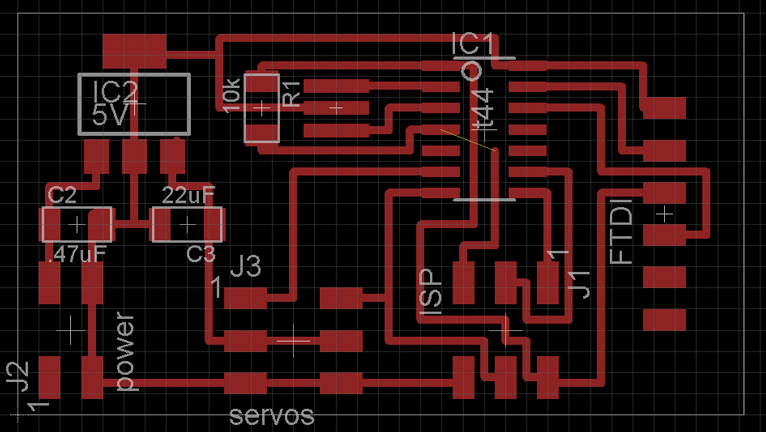
I stead of milling out a new board, I will first try to fix this by hand.
First I use a knife disconnect the wrong trace by cutting it trough.
Then soldering a little piece of wire, to connect the right traces.
It's not that pretty, but it works, setting the fuses works correctly now.
3.02 - Jumper Wires
3.03 - Deadbugs
http://workmanship.nasa.gov/lib/insp/2%20books/frameset.html
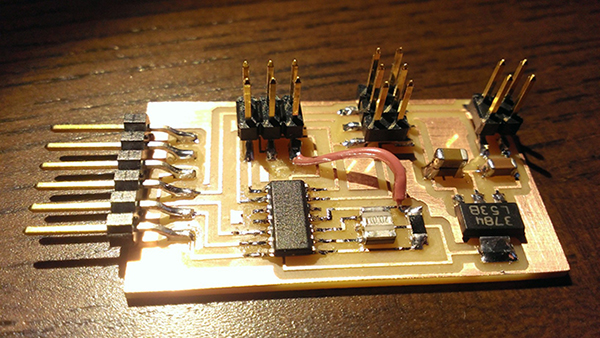
And testing with Neil's code works.
18 april 2014 | Programming
What the current software does, is switching between the 2 servo's.
It work fine, but as soon as the microcontroller switches to the other servo, the first servo stops doing anything.
And without constant direction it is possible to have an unwanted change of the servo's position.
For my final project in mind it is unwanted behavior.
The other option is using the hardware example code for the servo's,
But then I will only be able to use 1 servo.
The solution lies within using interrups. (based on the 16bit timer, and switching between high and low pins).
My tutor did a lot of explaining for me to understand what PWM is, how interrups works, and how to apply them to the code.
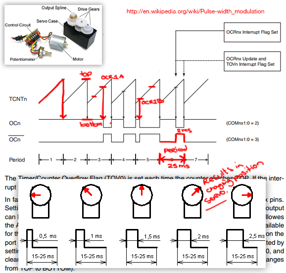
As base I used Neil example code: C (hardware PWM) & makefile
step1: renaming #define and add interrupt libary
#include < avr/interrupt.h >
#define servo1 (1 << PA6)
#define servo2 (1 << PA7)
#define servo_direction DDRA
#define servoMIN 1250
#define servoMAX 6400
#define servoMID ((servoMAX - servoMIN) / 2 + servoMIN)
step2: adding the interrupt service routine
ISR(TIM1_OVF_vect) {
set(servo_port, servo1 | servo2);
}
ISR(TIM1_COMPA_vect) {
clear(servo_port, servo1);
}
ISR(TIM1_COMPB_vect) {
clear(servo_port, servo2);
}
What happens is the setting the 'interrupt routine for the overflow of timer 1'.
And register A & B are 'cleared'.
step3: set up timer in the main(void)
TCCR1A = (0 << COM1A1) | (0 << COM1A0);
TIMSK1 = (1 << OCIE1B) | (1 << OCIE1A) | (1 << TOIE1);
'TCCR1A' means: Timer/Counter1 Control Register A
Reading the datasheet (page 106/107), I changed it to 0, since I want to control the pins instead of automatically.
'TIMSK1' means: Timer/Counter Interrupt Mask Register 1
The 0, 1 and 2 bit you want to add to the counter. This will add the interrupts.
Bit 2 - OCIE1B: Timer/Counter1, Output Compare B Match Interrupt Enable
Bit 1 - OCIE1A: Timer/Counter1, Output Compare A Match Interrupt Enable
Bit 0 - TOIE1: Timer/Counter1, Overflow Interrupt Enable
step4: set servo pin to output & enable interupts
output(servo_direction, servo1 | servo2);
sei();
step5: and add the servo routine to the while (1) loop
OCR1A = servoMID;
OCR1B = servoMID;
position_delay();
OCR1A = servoMID + 1000;
OCR1B = servoMID + 1000;
position_delay();
OCR1A = servoMID;
OCR1B = servoMID;
position_delay();
OCR1A = servoMID - 1000;
OCR1B = servoMID - 1000;
position_delay();
In the define rules I've entered the MIN and MAX that the servo is alble to rotate to.
In a second define rule I've left the program calculate the center of the servo's rotation.
So from the 90 degree position it can turn 2575 steps to the left or right.
The advantage is that if I later on decide to change the define rules, and the rest will automatically be re-calculated for me.
step6: connect the programmer to the board and 'make' the program
make -f hello.servo.44.make program-usbtiny