wk13 | networking and communications
Assignment :
- design and build a wired &/or wireless network connecting at least two nodes
Download : .c network code from touch sensor to servo
My notes :
24 april 2014 | trying example code
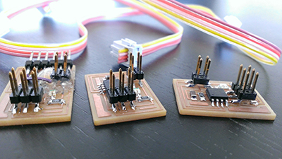
To get a better idea of how a simple network works, I started with trying out neil's
hello.bus.45 example.
My tutor already had the example boards ready, but the 6 pin headers were still missing,
so I soldered that.
Then I tried out the code to see how it works.
I used putty (tried in week 8) to get them to blink for me.
C:\dev\hello-bus>make -f hello.bus.45.make
#define node_id '1'
What is important, is that every board gets a different id, so when you ask (trough putty),
the right board blinks back.
So every node listens and all blink once, and the node addressed blinks a second time.
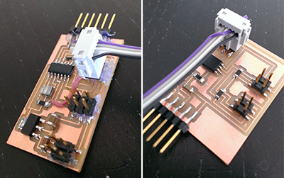
25 april 2014 | connecting my boards
For my final project I need my touch sensor board (made in
week 10) to talk to my servo board (made in
week 12).
Without changing the design of the boards, I can use:
| servo | > | touch |
| miso PA5 serial_pin_out | > | mosi PB0 serial_pin_in |
| sck PA4 serial_pin_in | > | sck PB2 serial_pin_out |
| vcc | > | vcc |
| gnd | > | gnd |
| > | ||
| > |
28 april 2014 | re-programming my touch sensor board
- sensor smoothing and math on avr
- fast moving averaging techniques
- cplusplus tutorials
With lots of explanation form my tutor about how my new code should work and why etc, I've written out a description of my code:
touch board - description:
function 1:
- continuous measuring
- calculating average of measurement
function 2:
- respond to request from master
- if request is directed to him, answer with giving the calculated average measurement
Note: We choose to communicate via a wires protocol.
Because of the limited available pins, we choose to communicate via serial connection.
(SPI > not enough available pins), (serial > RS232 is easier to debug than I2C).
How the 2 boards communicate:
- Master (servo board) will send a ID of 1 byte
- the addressed slave (touch board) will respond by sending back 6 averages of 2 bytes each.
function 1 - details:
- continuously measure 3 intervals from sensor 1
- continuously measure 3 intervals from sensor 2
- check if a byte has been recieved - if yes, send all the calculated average
- clear the received byte
after each measurement:
- else no, continue...
function 2 - details:
-
communications starts - main loop:
- check if a byte has been received (1 byte received: interrupt: respond within reasonable short time
- if yes, is byte same is own ID?
- if yes, respond with calculated results
29 april 2014 | new code for touch sensor
int16_t measure_interval_1 (); //declare functions
int16_t measure_interval_2 ();
int16_t measure_interval_3 ();
int16_t adc0_avg1, adc0_avg2, adc0_avg3; //declare varialble
int16_t adc1_avg1, adc1_avg2, adc1_avg3;
volatile char chr; //globale variabeles
void send_result (); //declare function
-------
void get_char(volatile unsigned char *pins, unsigned char pin, volatile char *rxbyte) {
void put_char(volatile unsigned char *port, unsigned char pin, char txchar) {
ISR(PCINT0_vect) { // pin change interrupt handler
-------
int main(void) {
// set clock divider to /1
// initialize output pins
// setup pin change interrupt on input pin
// initialize A/D/C
ADCSRA = (1 << ADEN) // enable
| (1 << ADPS2) | (1 << ADPS1) | (1 << ADPS0); // prescaler /128
chr=0; // initialize variable
sei(); // set enable interupts
-------
while (1) {
//set adc to PB4
ADMUX = (0 << REFS2) | (0 << REFS1) | (0 << REFS0) // Vcc ref
| (0 << ADLAR) // right adjust
| (0 << MUX3) | (0 << MUX2) | (1 << MUX1) | (0 << MUX0); // PB4 (sense)
int16_t lalala = measure_interval_1(); // the name (lalala) is(=) equal to 'result of function' (interval)
if (chr==0) {
adc0_avg1 = (3*adc0_avg1 + lalala) / 4; // when nothing happens, calculate and continue
}
else {
if(chr==node_id) {
send_result ();
}
chr=0; //back to staring value (clear)
}
// repeat for intervall emsurement 2 & 3
// set adc to PB3
// repeat for all intervall emsurements (1,2,3)
}
}
-------
int16_t measure_interval_1 () { // measure interval 1 fuction
int16_t measure_interval_2 () {
int16_t measure_interval_3 () {
void send_result () { // function to calculate and send result
1 may 2014 | re-programming my servo board
servo board - description:
function 1:
- have 2 servo's move independend
- (sending periodically position to servo)
function 2:
- periodically request sensor value's
- calcultaing new servo postion, bases on recieved sensor value's
function 3:
- fluent transition of old to new servo position
function 1 - details:
- generate PWM, based in timer
function 2 - details:
- requesting value's: - defining via serieel
- track time: have (+/-) 20ms passed? - if yes, send out ID, recieve the awser and rebuild the (new) value's
- value: is this number is less then the 'normal' value? - if yes, move servo in popsite direcion
- movement: is movement still possible without reaching the limit of the servo? - if yes, proceed with servo movement
- initialising via serieel
- if no, nothing happens
- else no, move servo in oppisite direction (note: this step still needs a better defined disciption to prevent conflict)
function 3 - details:
- optional (if time permits ...)
2 may 2014 | new code for servo board
#define servoMAX 6400
#define servoMID ((servoMAX - servoMIN) / 2 + servoMIN) // calculating steps to center position of servo
#define servoSMALLSTEP 100
int16_t adc0_avg1, adc0_avg2, adc0_avg3; //declare varialble
int16_t adc1_avg1, adc1_avg2, adc1_avg3;
volatile int clock;
char chr1_high, chr2_high, chr3_high, chr4_high, chr5_high, chr6_high; //declare varialble
char chr1_low, chr2_low, chr3_low, chr4_low, chr5_low, chr6_low;
-------
ISR(TIM1_OVF_vect) { // interrupt routine for overflow (and clock ++)
ISR(TIM1_COMPA_vect) { // interrupt routine for compare register A - timer 1
ISR(TIM1_COMPB_vect) { // interrupt routine for compare register B - timer 1
-------
int main(void) {
// set clock divider to /1
// set up timer 1
// initialize output pins
// set enable interupts
// send servo to starting position
// main loop
while (1) {
if (clock >= 3) {
clock=0;
put_char (&serial_port, serial_pin_out, '1'); // call to ID (touchsensor)
get_char (&serial_pins, serial_pin_in, &chr1_high); //receive answer
get_char (&serial_pins, serial_pin_in, &chr1_low);
get_char (&serial_pins, serial_pin_in, &chr2_high);
get_char (&serial_pins, serial_pin_in, &chr2_low);
get_char (&serial_pins, serial_pin_in, &chr3_high);
get_char (&serial_pins, serial_pin_in, &chr3_low);
get_char (&serial_pins, serial_pin_in, &chr4_high);
get_char (&serial_pins, serial_pin_in, &chr4_low);
get_char (&serial_pins, serial_pin_in, &chr5_high);
get_char (&serial_pins, serial_pin_in, &chr5_low);
get_char (&serial_pins, serial_pin_in, &chr6_high);
get_char (&serial_pins, serial_pin_in, &chr6_low);
adc0_avg1 = (int16_t)(chr1_high << 8); //rebuild values (highbyte/lowbyte)
adc0_avg1 += (int16_t)(chr1_low);
adc0_avg2 = (int16_t)(chr2_high << 8);
adc0_avg2 += (int16_t)(chr2_low);
adc0_avg3 = (int16_t)(chr3_high << 8);
adc0_avg3 += (int16_t)(chr3_low);
adc1_avg1 = (int16_t)(chr4_high << 8);
adc1_avg1 += (int16_t)(chr4_low);
adc1_avg2 = (int16_t)(chr5_high << 8);
adc1_avg2 += (int16_t)(chr5_low);
adc1_avg3 = (int16_t)(chr6_high << 8);
adc1_avg3 += (int16_t)(chr6_low);
if (adc0_avg1 <= 400) { // when yellow sensor (intv 1) is touched directly, servo's move the tail to the left
if (OCR1A + servoSMALLSTEP <= servoMAX) {
OCR1A += servoSMALLSTEP;
}
}
if (adc1_avg1 <= 470) { // when green sensor touched directly, servo's move tail right
if (OCR1A - servoSMALLSTEP >= servoMIN) {
OCR1A -= servoSMALLSTEP;
}
}
}