My final project
Final Project Description
My interest is in animatronics. I would love to master,
how to make something from scratch and let a shape come to life.
To have it looking around and respond to its environment, like sensing movement, light and sound.
inspiration:
http://en.wikipedia.org/wiki/Animatronics &
YouTube Animatronics Showreel 2011

What I would like is to make a dragon's head and tail.
I would like to keep the build as small as possible, so it can be easily transported.
I plan to start with completing the tail and touch sensor.
After consultation with my tutor, we agreed that finishing the head is optional/extra.
-
Moving parts :
- neck to move (example: https://www.youtube.com/watch?v=pB4tqn9tUX0)
- head to move (example: https://www.youtube.com/watch?v=pKf9VMGt540)
- face feature, like eye's blinking (example: https://www.youtube.com/watch?v=N0MBAXWjdL8)
- tail to move (example: https://www.youtube.com/watch?v=N0MBAXWjdL8)
- Electronics feature: Touch proximity sensing switch (example: https://www.youtube.com/watch?v=vKL_Q7vfkFw)
Within the project development page you can read about the earlier prototyping experiments.
mechanical design to shape my project
To give my final project shape I started with the mechanical design, witch consist of 3 pieces:
The box design and the tail design (and later I also added a travel case design for
obvious practical travel reasons).
Tail design
For my tail I wanted very flexible movement.
After some internet researching I started out with doing various small experiments
to figure out with type of hinge would suit me best.
- 1 way hinge: project development page - cardboard hinge test
The way of using sting to create movement work fine, downside is that I'm limited in my movement (only one axes). - 2 way hinge type (example):
https://www.youtube.com/watch?v=1GJNooFwNw8
This a very sturdy design, and the upside is that movement get constricted over 2 axes.
Downside is using so many acrylic pieces, the design get rather heavy for simple servo's. So: design constraint or buying stronger servo's - Softcore design. Very flexible design approach but everything depend on finding the right type of
softcore.
I tried messing with oomoo to see if I could make something myself, but I didn't really find that it worked to my liking.
So downside: so you need to buy a bungee cord type of material witch will act as hinge. - balljoint design. Range of movement can be easily limited by the way the curve is designed,
but you still get to keep movement in all directions.
Downside: you're not constraint in any movement, so torque effected can be a problem.
I choose to design a balljoint for my tail.
The inspiration for the design I found while browsing
trough the hardware store. Thinking that if I could have such smooth movement,
with some type of platform attached to it (for the wires).
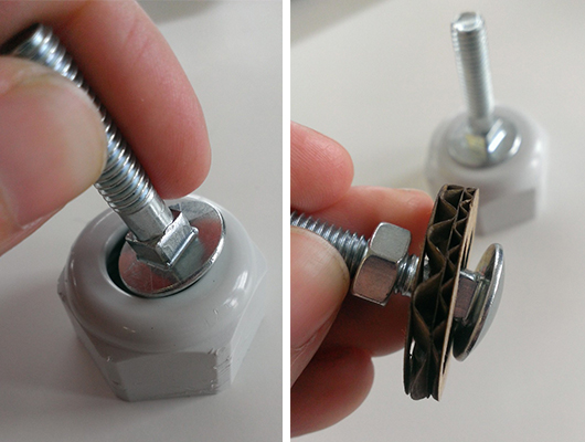
For my tail, I would like to have about 6 - 10 bending point's for a smooth and flexible tail.
During the mold & cast week I designed in Rhino a balljoint.
The mold & cast process is a good way to create many duplicates.
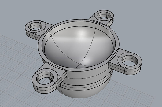
But I learnt that casting is not a easy process with a so small a shape.
I guess I could try re-designing the mold and try again for a better cast result.
But the hydrostone cast end result (so far) is a bit to fragile a material for me to serve as joint,
and at the moment we don't have other cast material options to try out in the lab,
so I opted for 3D printing the balljoint.
Printing one balljoint takes half a hour, and no raft/support material is needed.
So my end result is a clean and smooth as it can get with a 3D printer.
To smooth down the stepping a bit I used some fine sanding paper.
I also got the advise to try smoothing it out with acetone vapor,
I never got around to experiment with that.
Sanding it a bit works good enough for my prototype.
In the lab we got 2 3D printers: makerbot replicator 2 and the 2X.
So I tried printing with PLA and ABS.
It turned that PLA works better for me than ABS. As you can see in the photo below
the ABS printed seems
to get very damaged from movement over time, while the PLA has no such problem.
For my tail I ended up using 6 printed PLA joints.
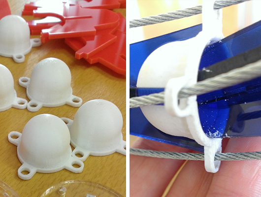
Stringing all my printed joint together I quickly
saw that movement is possible,
but that the joints need to be spaced further apart for a better movement result.
And a second problem is realignment of the joints.
Trough the force of the strings the joints move, but there is no force pushing them back to a center point.
This issue can be solved by adding springs into the structure.
To address the first problem I designed in illustrator 2 sets of pressfit 'spacers'.
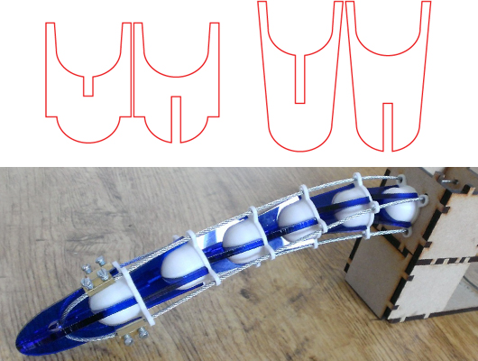
They are lasercut acryl slotted together to form a X shape.
The first set I tried prevent all movement of the balljoint, and the second set I tried had no limit at all.
The downside of that, is that when you pull to hard on the wires, the whole thing gets disjoint and falls apart.
I tried a couple of different combinations with both sets and found out that using 3 joint's gives you best control.
Where the bending point's are doesn't really matter, but evenly spaced apart works best.
When using more then 3 balljoints, the flexibility improves but the curling up effect become noticeable.
View movement test with the spacers
The next problem to solve is re-designing the spacers so I can fit springs in between.
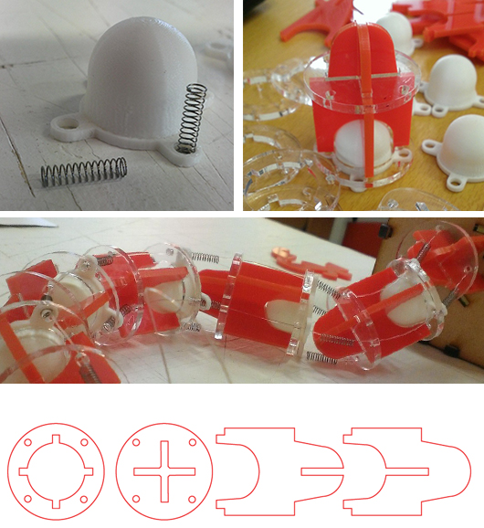
I found a local store that sells springs. This spring even fits nicely inside the the balljoint,
so that save me from having to re-designing the balljoint as well.
In illustrator I designed 2 disks to pressfit on the spacer part I already had.
The disks gives the springs a platform to push against,
and leaves also a smaller hole for the wire to still fit trough.
View movement test with the new spacers
As a final addition to this design I had to consider how to add the copper sensors to the tail.
I opted for adding small rib like clamps where I could add some vinylcut copper sticker to.
And I made a tail piece for the end of the tail.
Besides that it looks nice, this piece had a hole in it,
so I have a gap to tie the end pieces of the wires.
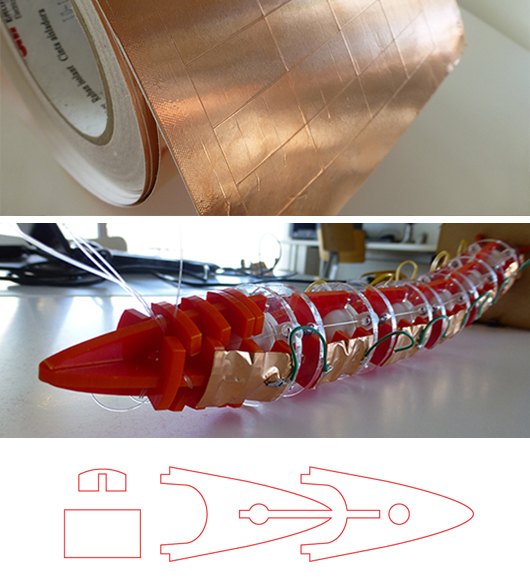
All the copper plates are soldered together and function as 2 big sensor.
The weakest point is the soldering, the way the copper stickers are connected.
The bending of the tail now forces the electrical wires to bend at the soldering point,
witch is quite fragile.
So after testing movement of the tail, some of the soldering points were broken again.
This leaves room for further improvement of the design:
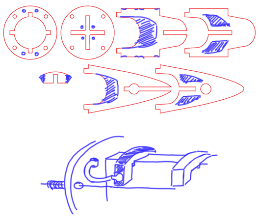
Future plan for tail design is:
to vinylcut some small copper strips that fit on the clamps.
The big copperplate will still be stickered on top of that.
The side of the clamp (now with copper) will be the new soldering point.
Extra holes can be added in the disks for the electronic wires.
The bending point will now the become the wire itself instead of the fragile soldering point.
And as a final change for this design the execs plastic can be cut away, leaving a more frame like shape.
This will reduces the general weight if the tail, and less stress for the servo's.
A lightweight short term solution for preventing a direct touch to the sensors, is adding vinylcut stips
wrapping separately around each tail joint.
For long term it would be nice to design/experiment with creating a mold & casted skin.
A recomended type for silicone for animatronics:
http://www.smooth-on.com/Silicone-Rubber-an/c2_1115_1129/index.html
Box design
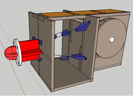
The function of this box is to keep the servo's in place, and to serve as a back plate for the tail.
The biggest effort went into designing it so that the wires had the least amount of friction as
possible in the transfer from the tail to the servo's.
The prototyping for this box has been done in wk14: mechanical design week.
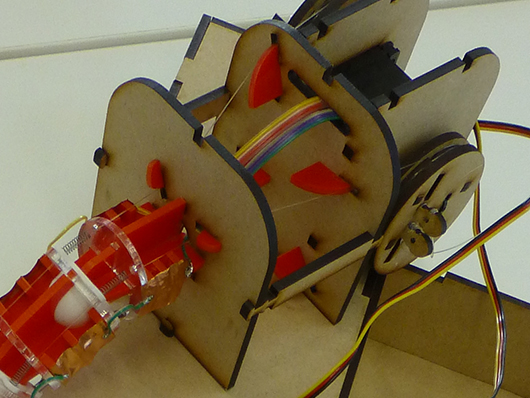
Designing the first version of cut sheets has first been done in illustrator.
Later on, when I wanted to make some improvements to the design, I've re-drawing it in Sketchup.
I experienced that it makes the tweaking of the design so much easier.
It was also my first time working with Sketchup.
Despite the small bugs in the program
(like the camera sometimes getting stuck in or behind some object
and note that this program doesn't create perfect circles but does do high polygon stepping attempt)
yet I really like the intuitive and simple way you can create objects.
Downside of the free version program is you need install a plugin
to get the export to sgv to work.
https://code.google.com/p/sketchup-svg-outline-plugin/
And with this pluging you can only export 1 object at the time.
And then go through the process of opening the file in inkscape,
edit the lines to 0.01 millimeters & export to PDF.
A other issue I had was the work size of my file. Sketchup doesn't work with smaller the millimeters
And I do need that detail, if I want my design to be pressfit.
As solution I ended up working with a template in meters.
And down scaling the whole design to millimeters before exporting to svg.
(downscaling form meters to millimeters is 0.001 factor.)
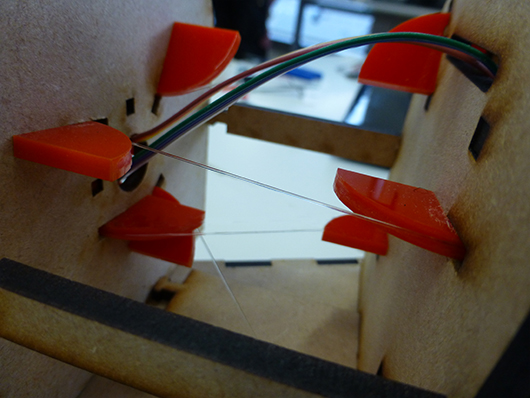
What I like about this design, is the whole is pressfit, no glue needed.
By adding the little round red pieces of plastic the wires is guided over
round corners in stead of sharp wood corners.
As a minor tweak I filed gutters in each plastic piece, to keep the wire in the center of the plastic.
And I also tweak the wheel design a bit to better fit for fishing wire in stead of metal wire.
You can read more about the first version of this design is on the
project development page.
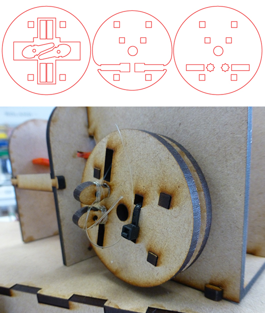
- Inspired by the knob of a guitar I made 2 pins where I can fasten the fishing wire to.
The main advantage of doing it like this versus a regular knot, is that if the wires stretches over time
(like with a guitar string) it is quite easy to adjust it to the desired tension. - The extra hole in the center of the wheel give me excess to put a screw trough the red cross into the servo.
- The tie wrap keeps the red cross in place.
- The 4 pins keep the wheel pressfitted together.
Future plan for box design is:
Adding some small tweaks to this box design.
I would like the front piece of the box (where the wires crossover) to be a small as possible.
When I made this design I intended to use metal wire, witch is no longer the case.
And I would like that the electronic boards get fixed place on top of the box.
The boards can be held in place by little wooden pins/hooks.
And then the top of the box can be protected by a lid/hood/covering.
And in the back, next to the servo's a bit of extra space is needed to hold the battery in place.
Travelbox design
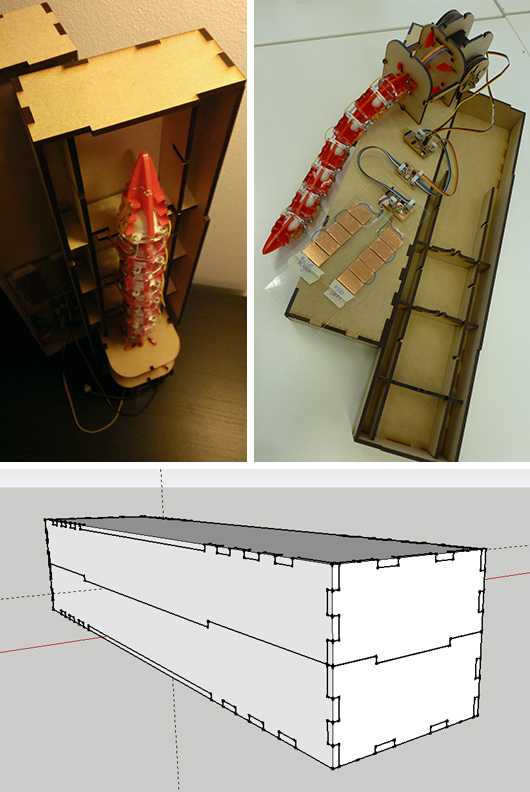
The function of this box is obviously keeping my work protected during travel. :)
I travel a lot back and forth with public transport and needed a way to prevent damage
if I wanted to continue working from my home.
It's also a pressfit lasercut design, made with Sketchup.
The grid inside the box has little slots where 3 of the tail pieces can be fit in.
Simple rubber bands keep the tail in place.
The electronics can be disconnected, and travel in a separate bag.
electronics design, 2 touch sensors connected to 2 servo's
My goal for this final project is to make a autonomous animatronic.
To make that possible I can use the electronics designs I have made in the previous weeks,
and re-design them for this prototype.
-
What needs to be done:
- board to drive the servo's (board can stay the same, C code needs to be edited)
- board to measure the sensor's (new board, new sensors and new C code > txrx)
- network code: (master/slave) the servo board will ask for value from the sensor board and translate this into movement for the servo's
- extra: a connector board that fits in between the servo & sensor board, and provides the battery connection and a reset button
New sensors
In input devices week I've made a board with touch sensors, designing this using the load45
example code.
I got that model to work (movie of testing my sensors)
but I noticed that this type of sensors, picks up a lot of background noise.
So where ever you setup for testing, it responds differently, and if there are many people around or other electrical devices,
the sensors are influenced.
Neil gave me the advise to try the same setup but then using the txrx sensors.
(example code)
Since those should be less sensitive to background noise.
For creating the new sensor board, I edited the design I had already made for the previous set of sensors.
Reconnecting the two pinheaders and adding in extra resistors.
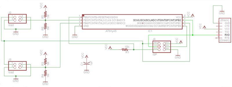
My board design is now prepared for 2 new sensors. After milling on the Modela and soldering the board is ready.
For making new sensors I used some copper sticker rectangles (cutout via the vinylcutter)
and decided to first make a test model, before aplying them to my project.
I used 2 leftover pieces of acryl to isolate the sensors from still being influenced to much by background noise.
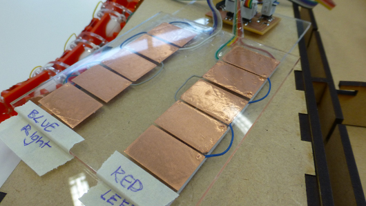
Next step is making the connector board.
The idea for making this extra board was born from the irritation while building the first network
(week 13).
Back then I choose not not create new board but to re-use pins.
To make that work I needed wires too cross, from one board to the other.
And every time while testing you need to think and check again if the pinheader is connected the right way around.
To prevent this I could, off course, choose to also re-design my servo board and solve the main issue.
But my tutor gave me the suggestion to opt for a new/extra board and use this chance to add a reset button to the circuit.
I ended up designing a simple schematic solving the crossed wire issue by crossing the traces on the board.
I added the power supply connector, a LED (power supply indicator) and a reset button (for testing).
I also wanted to add a power switch, but choose not to, because I found that switch is so tiny,
using that is more of a hassle then pulling the battery header loose from the board.
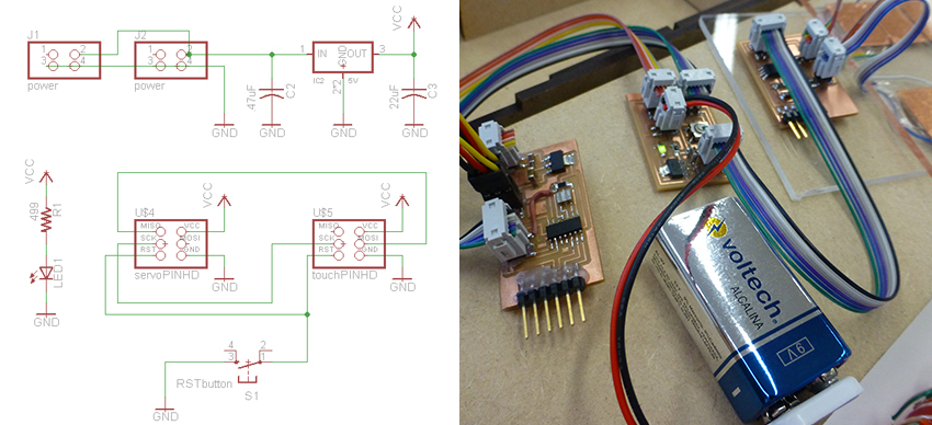
Now all my boards are ready, I checked first if all my connector where soldered properly with the continuity tester.
All appears fine, so next step will be programming.
Programming touch sensor: (hello.txrx.45.c)
Like with the previous sensor board, this code is meant for 1 sensor.
So the first set is editing the main loop.
Letting it stitch between 2 sensors, instead of measuring only one.
And to make the main loop less messy, I created functions for measuring, framing and sending result
- ADMUX (PB4) moved from initialize to the main loop
- copied in a second ADMUX for PB3
- cut the measuring, framing and sending result code out of the main loop,
and moved it to separate functions.
while (1) {
//set adc to PB4
ADMUX = (0 << REFS2) | (0 << REFS1) | (0 << REFS0) // Vcc ref
| (0 << ADLAR) // right adjust
| (0 << MUX3) | (0 << MUX2) | (1 << MUX1) | (0 << MUX0); // PB4 (sense)
// fuction measuring value
uint16_t sensor1_raw = measuring();
// set adc to PB3
ADMUX = (0 << REFS2) | (0 << REFS1) | (0 << REFS0) // Vcc ref
| (0 << ADLAR) // right adjust
| (0 << MUX3) | (0 << MUX2) | (1 << MUX1) | (1 << MUX0); // PB3 (sense)
// fuction measuring value
uint16_t sensor1_raw = measuring();
send_framing ();
send_result ();
}
}
Next step is letting the sensor board calculate the values (measuring, filtering) instead of in python.
while (1) {
// fuction measuring value
uint16_t sensor1_raw = measuring();
if (sensor1_raw < 5000) {
sensor1_filtered = (3*sensor1_filtered + sensor1_raw) / 4; // calculate filtering valvue
}
// repeat for PB3 sense as well
}
}
// and adding in the measuring function :
return (up - down);
Programming phyton: (hello.txrx.45.py)
And although python is no longer necessary, the interface is is useful as a debugging tool.
That means (like done in interface week) dubbeling the filter code,
and because I don't want python to calculate the sensors values, I removed this code.
filter1 = 0.0 # filtered value
filter2 = 0.0 # filtered value
# read and plot
S1_low = ord(ser.read())
S1_high = ord(ser.read())
S2_low = ord(ser.read())
S2_high = ord(ser.read())
# rebuilding value
S1_value = 256*S1_high + S1_low
S2_value = 256*S2_high + S2_low
# calculating value moved to C code:
# value = (up_value - down_value)
# filter1 = (1-eps)*filter1 + eps*value
# filter2 = (1-eps)*filter2 + eps*value
x1 = int(.2*WINDOW + (.9-.2)*WINDOW*S1_value/10000.0)
x2 = int(.2*WINDOW + (.9-.2)*WINDOW*S2_value/10000.0)
canvas.itemconfigure("text1",text="%.1f"%S1_value)
canvas.itemconfigure("text2",text="%.1f"%S2_value)
#re-designing the interface to my liking
canvas.coords('rect1',.2*WINDOW,.05*WINDOW,x1,.1*WINDOW)
canvas.coords('rect2',x1,.05*WINDOW,.9*WINDOW,.1*WINDOW)
canvas.coords('rect3',.2*WINDOW,.15*WINDOW,x2,.20*WINDOW)
canvas.coords('rect4',x2,.15*WINDOW,.9*WINDOW,.20*WINDOW)
Debugging
In the touch sensor code I turned off the send framing and send result,
and connected the board to the computer to first test the new sensors with a python interface output.
And off course the result at first was ... it works, but python interface responds very sluggish
So I connected a logic analyzer to my board, so see if I could figure out what is wrong.
My first thought was maybe the edit of the calculation of values on the touch sensor board slows the whole process down.
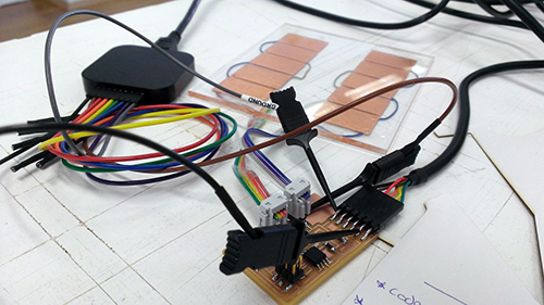
What become obvious with the logic analyzer, is that the calculating values part is not the problem.
But the measuring part of the routine takes long.
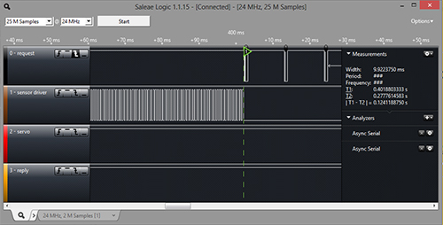
| 124 ms. | transmit | > mesuring sensor 1 (100 times) > mesuring sensor 2 (100 times) |
| 0.3 ms. | > calculating values | |
| 80 ms. | data | > sending |
#define char_delay() _delay_ms(1)
// changed the loops to accumulate from 100 to 50
#define nloop 50
// and there was one wrongly placed char delay.
This on has been moved from send results function to the framing function.
And one other thing that I noticed when looking at the py interface.
Sometimes, without reason, the sensor value peak extremely.
I have no clue what causes this, but after consulting with my tutor,
he said then this problem can be ignored by editing a valued IF statement in the servo code.
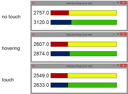
adding the network part 1
Now my touch sensor works, the next step is letting it communicate with my servo board.
That means that my touch sensor should be able to handle a interrupt service routine.
And being able to respond with the calculated value as answer.
#include
#define serial_interrupt (1 << PCIE)
#define serial_interrupt_pin (1 << PCINT0)
#define node_id '1'
-----------------
// fuction: add pin change interrupt handler
ISR(PCINT0_vect) {
get_char(&serial_pins, serial_pin_in, &chr);
// put_char(&serial_port, serial_pin_out, chr);
// clear interrupt flag ( which was set by the pin changing during the interrupt )
GIFR = (1<
-----------------
int main(void) {
// adding this to initializing in the main loop
// initialize output pins
set(serial_port, serial_pin_out);
set(serial_port, serial_pin_in);
// setup pin change interrupt on input pin
set(GIMSK, serial_interrupt);
set(PCMSK, serial_interrupt_pin);
chr=0; // initialize variable
sei(); // set enable interupts
-----------------
// adding cli in the for loop, this is the only moment you don't want to be interrupted
uint16_t measuring () {
for (count = 0; count < nloop; ++count) {
// settle, charge
settle_delay();
cli(); //clear interupt
set(transmit_port, transmit_pin);
// initiate conversion
ADCSRA |= (1 << ADSC);
sei(); // set enable interrupt
-----------------
// and adding this very important part to the main loop
while (1) {
if (chr==node_id) { // only send result if commanded by master board
chr=0; //back to staring value (clear flag)
send_framing ();
send_result ();
}
adding the network part 1
Now that the touch sensor code is truly complete, the final step for now is getting my servo board to communicate as well.
#define servoMIN 1250
#define servoMAX 6400
#define servoMID ((servoMAX - servoMIN) / 2 + servoMIN)
#define servoSMALLSTEP 100
-----------------
int main(void) {
sei(); // set enable interupts
// send servo to starting position
OCR1A = servoMID;
OCR1B = servoMID;
_delay_ms(1000);
-----------------
// main loop
while (1) {
if (clock >= 3) { // after waiting for the clock to turn 3 times routine will be excetuted
clock=0; // reset clock
put_char (&serial_port, serial_pin_out, '1'); // call to ID (touchsensor)
get_char (&serial_pins, serial_pin_in, &tmp); // ignoring recieved framing
get_char (&serial_pins, serial_pin_in, &tmp);
get_char (&serial_pins, serial_pin_in, &tmp);
get_char (&serial_pins, serial_pin_in, &tmp);
get_char (&serial_pins, serial_pin_in, &chr1_low); //receive answer
get_char (&serial_pins, serial_pin_in, &chr1_high);
get_char (&serial_pins, serial_pin_in, &chr2_low);
get_char (&serial_pins, serial_pin_in, &chr2_high);
sensor1_filtered = (uint16_t)(chr1_high << 8); //rebuild values (highbyte/lowbyte)
sensor1_filtered += (uint16_t)(chr1_low);
sensor2_filtered = (uint16_t)(chr2_high << 8);
sensor2_filtered += (uint16_t)(chr2_low);
if (sensor1_filtered <= 2500) { // if red/yellow sensor is touched, servo's move the tail to the left
if (OCR1A + servoSMALLSTEP <= (servoMAX - (2*servoSMALLSTEP))) {
OCR1A += servoSMALLSTEP;
}
else {
OCR1A = servoMAX; //smack movement when tail is at servoMAX
position_delay();
OCR1A = servoMAX - 4*servoSMALLSTEP;
position_delay();
OCR1A = servoMAX - 2*servoSMALLSTEP;
}
}
if (sensor2_filtered <= 2600) { // if blue/green sensor is touched, servo's move tail to the right
if (OCR1A - servoSMALLSTEP >= (servoMIN + (2*servoSMALLSTEP))) { // can I move? if yes, then move to ...
OCR1A -= servoSMALLSTEP; // nieuwe positie
}
else {
OCR1A = servoMIN; //smack movement when tail is at servoMIN
position_delay();
OCR1A = servoMIN + 4*servoSMALLSTEP;
position_delay();
OCR1A = servoMIN + 2*servoSMALLSTEP;
}
}
}
}
}
So code complete, and when testing, it the tail moved, jheee. :D
At the moment the sensor works best if you let you hand hover above the sensor. So a bit of fine tuning is still needed.
And the idea that it smacks back when it can't avoid you, doesn't work yet. Sadly out of time for the presentation deadline.
But I am pleased to see that this new set of sensors now works, and now less influenced by background noise.
Future plan for this project:
I still would like to finetune the sensors. The sensors need to be placed on the tail itself.
And I think that if the electronic boards (and sensors) get a permanet spot on/in the tailbox,
it would be less effected by'background noise' and give more stable mesurements.
And I could expand the sensor set from 2 to 4 sensors, so all of the tail is covered.
It would also be nice if the tail response is quick and fluently over both axes.
That means writing a more sophisticated program behaviour loop for the tail (servo board).
As for long term planning: I'm far from finished, and there is much more to learn for me about electronics and mechanics.
I really enjoyed this whole process and my plan is to continue working on this project, hoping to create a full body creature.
