wk14 | mechanical design, machine design
Assignment :
- design or modify a machine, making as many of the components as possible
- make the passive parts and operate it manually
Download : PDF + sketchup design file
My notes :
25 april 2014 | Designing the box
For my final project I would need a structure where 2 servo motors and the tail pieces
can be mounted.
In the previous week I already build a
first version of this box. For this week assignment I will make a improved version of this box.
The concept is that the tails joints move by pulling on wire,
which is roped trough all the pieces.
By pulling the tip of the tail first, (since the knot is there), and then the rest of the joints will follow.
Pulling one wire will cause the joint to move on one direction. For moving in opposite direction, a second wire is needed.
Big problem lies in re-alignment the joints back in the center without using gravity (like the cardboard joint example).
The wires can only pull, not push. Therefore springs are necessary to be incorporated in the design.
First step will be figuring out how the wires will run trough the new design.
Previous design already is a rough idea of how the design should be,
but now providing that the wires move with the least amount of friction possible.
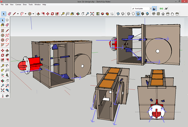
That gives two problem to consider:
first: metal wire. I want to prevent that it moves directly over mdf box. And no sharp angles.
second: crossing of wire's. They should not touch each other, so figuring out angles is important.
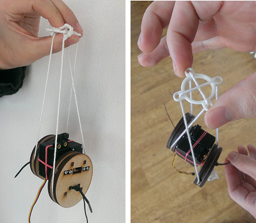
The white (3D printed) circle thing represents the tail.
And the wires (from tail to servo) need to be cross connected.
the top left and bottom right wire need to be connected to the right servo.
And the top right and bottom left wire will be connected to the left moter.
So one servo will create left and right movement, and the other will provide up and down movement.
The final placement of the wire's in the box design is diagonal.
so, moving with used one sevo will cause the tail to curl to the right side (diagonal) up or to the left side (diagonal)
down and vice versa.
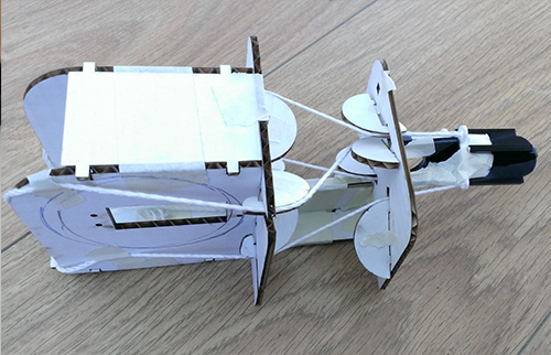
Several (cardboard) test versions, I ended up with this press fit concept.
For now I choose not to focus on where the electronics should be placed within the box,
because I'm not sure if if will change for my final project version.
But there is place enough to fit the boards on top of the box, and add some covering over them.
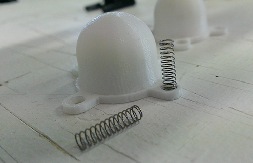
The second part of my design in changing the tail to solve the spring problem.
I've found a local hardware store that sell's springs.
I think that if each ball joint will get's 4 little springs, the movement of ech joint will be improved.
That means that every blue spacer piece needs a extra plate to give the spring something to push against.
More about the tail design is discribed on the final project page.
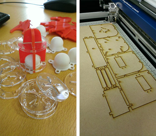
I have designed the new tail pieces a bit bigger then the original blue one's.
Problem now is that the metal wires I had used before, are to short.
Fortunately, in the FabLab inventory is also a roll of fishing wire (with strength up to 10kilo).
And after testing, it turns out that I prefer the fishing wire over the metal wire.
The result is a much more fluent movement and less friction the metal wire.
The only thing that's needs changing now is the wheel.
The original wheel design was ment to hold metal wire,
on my final project page you can see how I adjusted the design
for fishing wire.