
1.18 NOISESTORM Project Development
DISCLAIMER: If you want to fab it. We make no claims about the safety of the below techniques or about their appropriateness for any purpose. Use at your own risk and consult experts on electronics safety.If you are looking for the other project: QUORE go to its page
The assigment:
work on your machine and final project, documenting your progress:
3. NOISESTORM
3.1 Overview
A solar storm amateur mini radio telescope. Everybody can be a radio astronomer
3.2 : CONCEPTUAL MODELLING:
There is a system architecture defined on this document: How to build your own Radio Telescope (page 11 of the .pdf file). But it only defines in a basic high level:
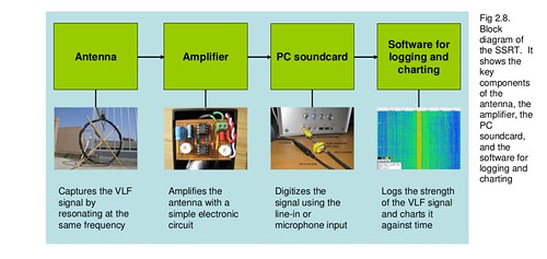
These is the structure of the components needed to create, and it is also the way we can make a work breakdown. In the end we only need to integrate the components to obtain the result. Our work then is to make independently a VLF antenna, an amplifier, a soundcard (we can reuse the one that is usually integrated on laptops), and a application interface.
3.2.A - VLF Antenna: Because of the basic architecture, the VLF antenna can be replaced with a simple antenna but it will only receive and amplify the electrical noise in the environment
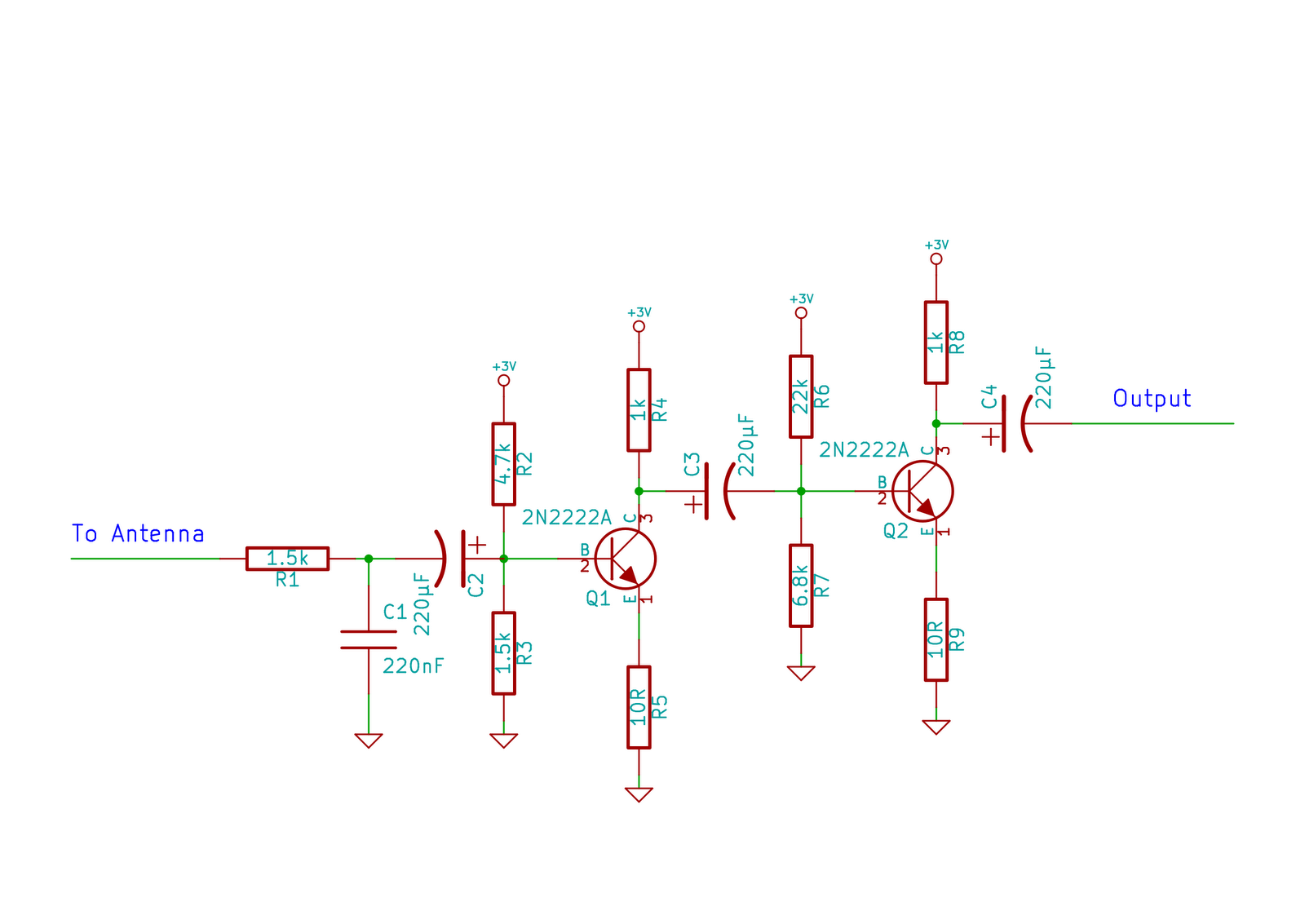
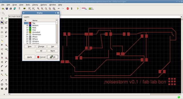
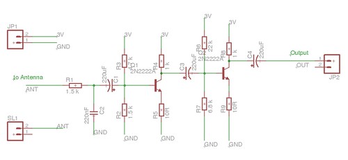
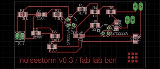
3.2.B - Amplifier: There is a basic circuit schematic of John Brooks but there is only a image of the schematic not the circuit design so it was necesary to translate the schematic into an eagle design.

3.2.C - Digitalizer: reuse the soundcard audio input port
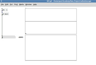
3.2.D - Application interface: a software to process the data received. It is possible to use an oscilloscope at testing level and then use code that reads the sound card in Pure Data, Processing or any language.
3.3 : DIGITAL MODELLING
3.3.1 : Physical structure
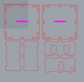
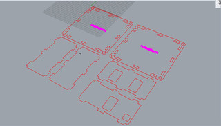
A box is designed based on the ADBO original design, given the size demands and scale is made, but given that the material is of the same thickness and has not changed, the design needs to be redraw maintaining the holes sizes. In this case we are not using parametric design.
3.3.2 : Instrumentation
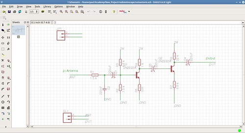
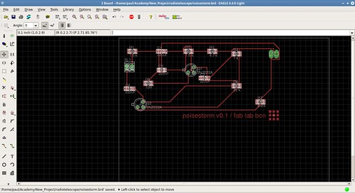
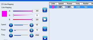
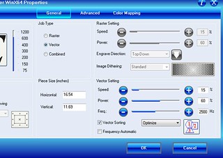
An amplifier circuit board is prepared using Eagle PCB Design software. The design is of John Brooks but he only release an image and not documented the details, because of that was necesary to read all the forum and then redraw the circuit from the ground up.


3.3.3 : Computation
To read the input from the sound card we have several options:
3.4 : PHYSICAL MODELLING / FABRICATION
3.4.1 : INGREDIENTS
Basic materials from inventory
Digital stuff (Bits)
Physical stuff (Atoms)
3.4.2 : INSTRUCTIONS
Steps


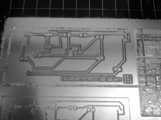
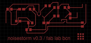
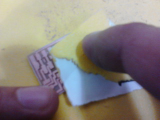
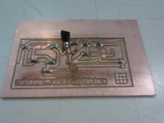
Because the lab were out of 1/64 milling pins the milled board need some hand finish. (The images are referential because the photos are of another circuit board.)
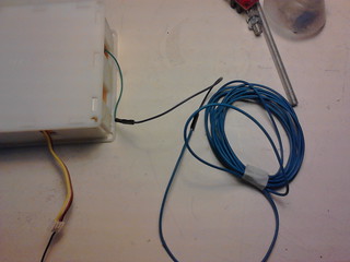
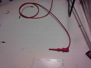
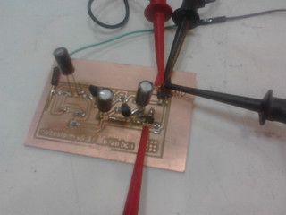
After that manual error-correction, all the components were solded, including the antenna (shielded copper wire).
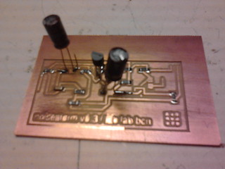
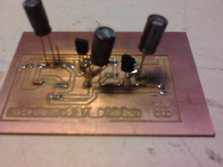
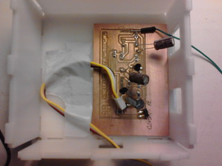
Because of the unavailability of some components, the three 220uF capacitors and the two 2N2222 transistors are of a different technology (THT).
First run
Second run
Third run
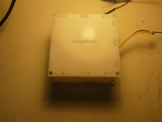
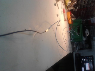
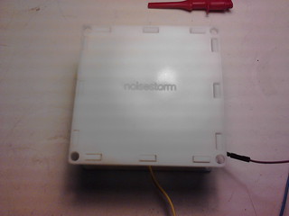
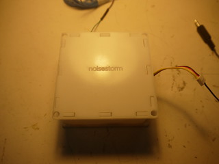
The NOISESTORM box and the antenna
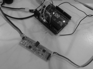
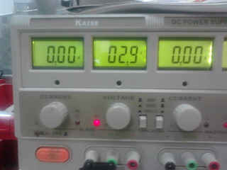
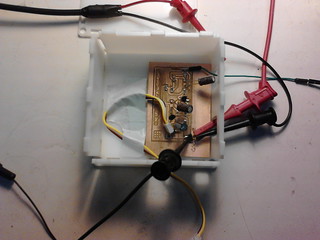
We are using a power source, and an oscilloscope also.

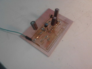
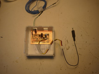
The NOISESTORM circuit board inside its box, with only the antenna and the jack output connected. Then the oscilloscope and the power supply is connected.

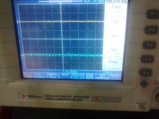
RESULTS
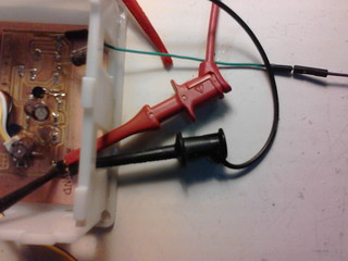
The board was tested successfully. A power source (Kaise DC Power Supply HY3003D-3) was used in order to provide with 3V, an antenna was connected and the output was connected to an oscilloscope (Promax 0D-581).
The NOISESTORM circuit is design based on drawings published at Fast Quake. At the time of the experiment, the transistors and capacitors required were not available. The especifications of the circuits showed its the same as the design but are replaced with corresponding ones of a different technology (Through-hole technology).
The power supply is a KAISE HY3003D-3 machine and the oscilloscope is a PROMAX OD-581.

4. CREDITS AND ACKNOWLEDGEMENTS
Credits
Acknowledgments
Inspirations from HTMMA