Electronics - Final Academy
Menu Principal:
Electronics
Week04. Making Boards. CNC and Welding
Our I-
The first process of the week was try send the *.rml from FabModules to the Roland machine, but we had problems with the ports or directly with the code for the machine.
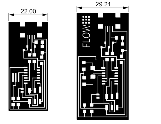
The board choosed in the first try was the ISP that use a Cristal 20MHz. We made some correction or modifications in the size to do more easy the welding process. This week was our first welding time.
Jose Pérez de Lama, aka Osfa, made the best summary of the week of FabLabSevilla. In our team, anybody have experiences with electronic or welding, so we worked together all the week.
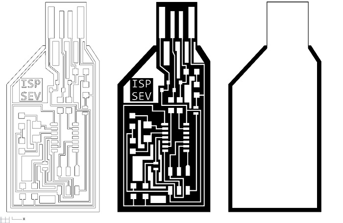
Down, the size correction. We name it FLOW ISP
FabModules_vs_I-
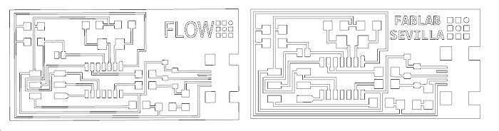
Quickly, we started working with Inkscape to vectorize the *. png. OSFA had already made changes to the board that incorporates the "crystal", so, with we had two vectorial files to work with the I-
The I-
Pic of vector files used.
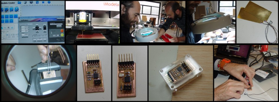
Milling Process
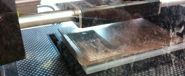
Okay, I-
To get the cut piece, we used a Proxxon disc-
Tricks and traps....
The first consequences of use I-
To send a work to the machine we used the Roland software, I-
Using FabModules, we can choose the number of offset that we want to cut or engrave, but not in I-

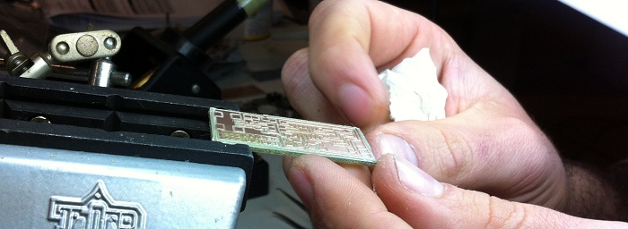
We hope that the FR1 board will be more easy to be mill. For this week we only got three finished boards with some mistakes in the traces. When we was completing the welding process, some copper traces were removed from fiber board... and we had lost the posibility to finish the board totaly. Counting the components, we discovered that we don´t had the diodes required, already been purchased and are sending it.
The pic show the last result of the week

Well, now my summary:
In the up text you can read some happy solutions. But this week was very very long!!!
1. Conect I-
No port. No the same language.
2. Try to made the board with the Alaris30 machine. Not posible.
0.016 inch tool diameter, with long flutes, all broken.
The work surface was not horizotal totaly in some tries.
3. Without FR1. We worked with FR4, very hard, and dificult to be cut.
4. I-
5. First time welding. This not was a problem, I´m happy with the results.
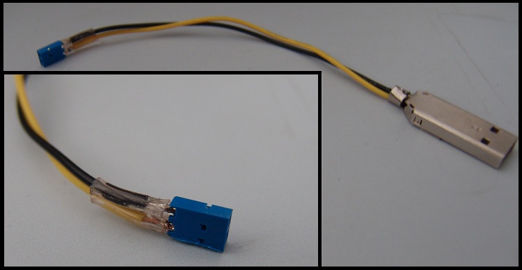
6. The only difficult part to be soldered was the USB conector. I saw the Valentin
board, here the mini-
My last work this week was draw a new PCB that mix the Valentin´s idea and the board that we used. I hope it run!! Now we await the arrival of the diodes to continue working.
Week06. Electronics Designs
New electronics sesion.
My knowledge of electronics is very basic, and really, I do not really know what we're doing, but I like it! In the last five years, there have been FabLabSevilla over five workshops related to electronics, and I always had fled from them. Right now ... every time I attempt to identify components of a PCB, although I did not what each one.
This week I followed step by step tutorial Anna Kaziunas, thank you. It was my first contact with Eagle, and electronic schemes, and I spent several days reading manuals and looking for some commands. Now I consider myself a beginner master!
Following Anna's tutorial Kaziunas.
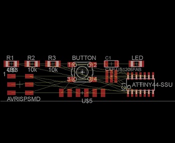
I downloaded the files of the board "Hello_Echo". I opened the diagram and follow the steps to add the missing components, resistors, LED and button.
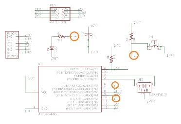
At first, some wires were not connected where they should. I believe that Eagle did not recognize GND or VCC blocks, so delete them, and I named wires. Additional, components "LED and Button" conflicted with the wires "LED and Button" from the microcontroller, so I changed the name of outputs from the micro, and the wires from the components, "L and B".
It is likely that these changes were not necessary, perhaps the problem is that I do not use Eagle. I sensed these "mistakes" by passing the drawing screen for plates. I was not able to distinguish the "yellow connections" and the autorouter did strange things.
After several attempts and corrections self, all components are connected correctly. It's time to route the board.
Now ... the autorouter is a horror ... I tried to make a placement own for components, but most of the connections are crossed. truly, I ran out of week. no time for milling. So, I reset all the components in place, as in the tutorial, and mainly, I modified the "Design Rules", to then, draw the conection by hand with the "route" tool.
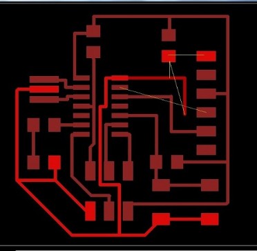

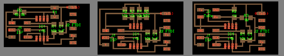
In terms of change of the "Design Rules" It took me a while to discover the system of units used for each modification, it is unclear when used when used milimeters or inches. I did not know the unit "mil", 0.001 inch. Knowing the units used, the photograph shows the chosen values. In general, 16 mil for each change, 0.016 inch or 0.4069 mm.

To make the board, export it in *. Png (monochrome).
VCarve Pro I used to create the file sent to the router, our Alaris30.
In this software, we can create the vectors from images. I used a milling cutter with a diameter of 0.016 inches.
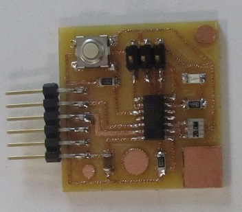
I pre soldered only a pad for each component, and then, with the board fixed on the third hand, I soldered each component easily.
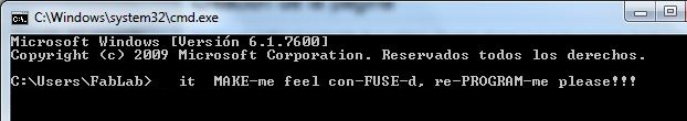
Week08.Embedded programing/ Program Board
This week, no doubt, has been the most difficult to tackle. A field too abstract and unknown to me. Without venturing far, I be sure to get go further over the coming weeks, but for now, I just follow the steps taken by Jose Perez de Lama to perform part of the homework.
Jose Perez de Lama has been helping us during the week to understand concepts that we could not decipher. Meanwhile, Alejandro Campos, Masters in Industrial Engineering in the field of electronics, we explained the most complex part about programming languages and the inner workings of the microprocessor, in this aspect, Juan Carlos Venegas explains on its Web everything relevant.
Before discussing the results, I have to confess that not all circuits worked. Specifically, it seems there is a short circuit between the microcontroller and the button on my board ... even correcting some welding, the plate is still not working.
I thought about making a new board, using the circuit of Jose Perez de Lama, if it works correctly.
Course of the week:
Reading DataSheet. I remained stuck in a few days reading the summary. I could not explain what I read, but the notes made by Alejandro and Jose helped me to understand a few lines of the program that we choose.
Down, the three points that I understand:
Pins
We have 8 + 4 pin, separate PA and PB, each of these pins can be used as input or output. The use of these will be specified in the program, first calling the pin, then determining if this is an input pin or an output, and then open or close as needed. The other two pins are GND and VCC.
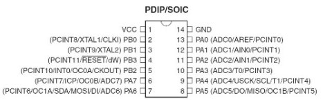
In ATTINY44 there are three types of memory.
FLASH.4k. Memory hard. Here are stored the necessary programs.
EEPROM.256 b. Memory hard. Here are stored the data needed for the program.
SRAM. 256 b. Volatile memory. Here are stored the data produced or received. Clears the reset.
Clock.
The internal clock runs at a speed ATINY44, we placed a crystal to greatly improve the speed.
Programming. Mournfully, I have not learned to program in C or Python or anything. Although, I have learned something about the different programming languages, or rather, about language levels.
High level >> Python >> needs to be interpreted
Middle level >> C >> needs to be compiled
Assembler >> Low >> machine code (for us *. Hex)
Objective. Find a circuit similar to ours. Microprocessor> LED> button
Find a program (C) to do something with them.
Understand how it works.
Jose discovered the work of Travis Rich, HTMAA student.
We used their promagra, written in C, to turn on the LED when you press the button, counting certain delay.
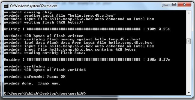
We used to compile hello.ftdi.44.echo.c, written by Neil G. an we followed the steps from one of the "class files"
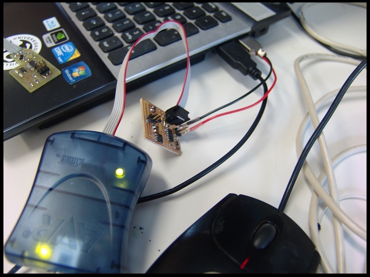
AVRISP mkII was used. First installed AVR dude.
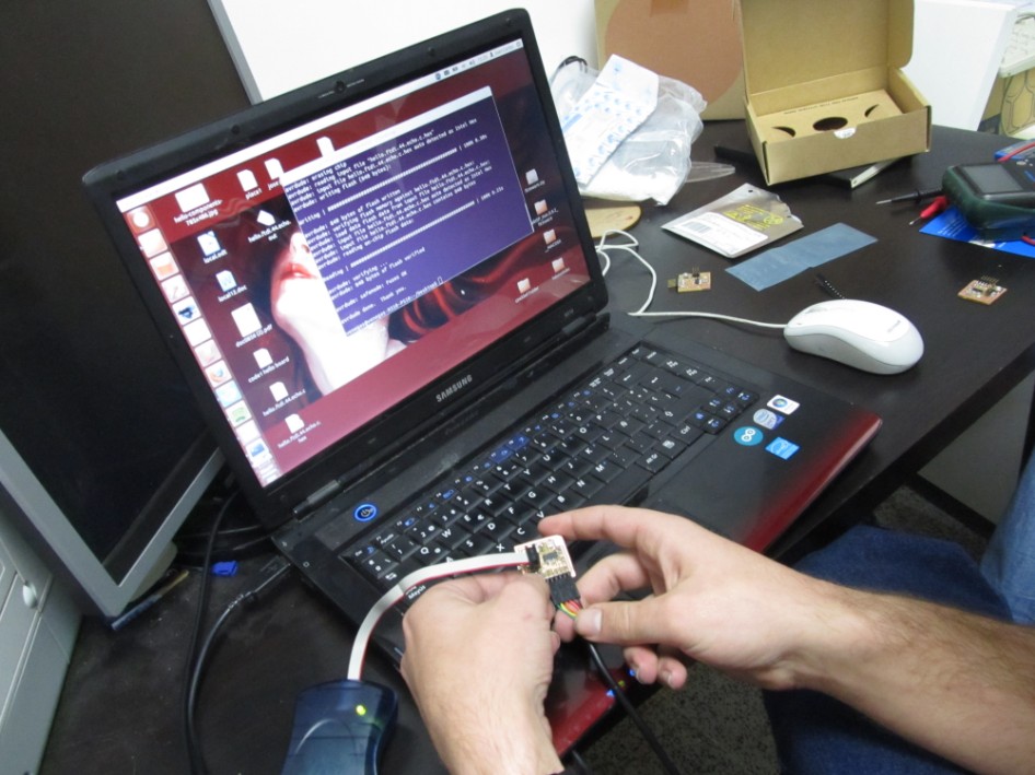
The week has been short. But we were able to load the program to one of the boards that we prepare for Week 06. I hope to learn a lot more about programming.
Happy Embedded !!!
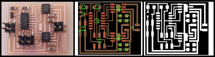
Week10. Inputs
It was a great end of assignments! I started the week quite worried, I have been on the coast during the holidays, I've gotten off, but I thought this week would not get complete homework. Quite the opposite, Jose Perez de Lama worked for everyone during the holidays. When I arrived on Monday, two boards were milled, Jose Perez explains, and the third was milling by Juan Carlos Perez while Jose Perez and me weld.
Before going on holiday, we specify that examples do. We count components and decided to make the following three:
hello.lignt.45 hello.temp.45 hello.txrx.45
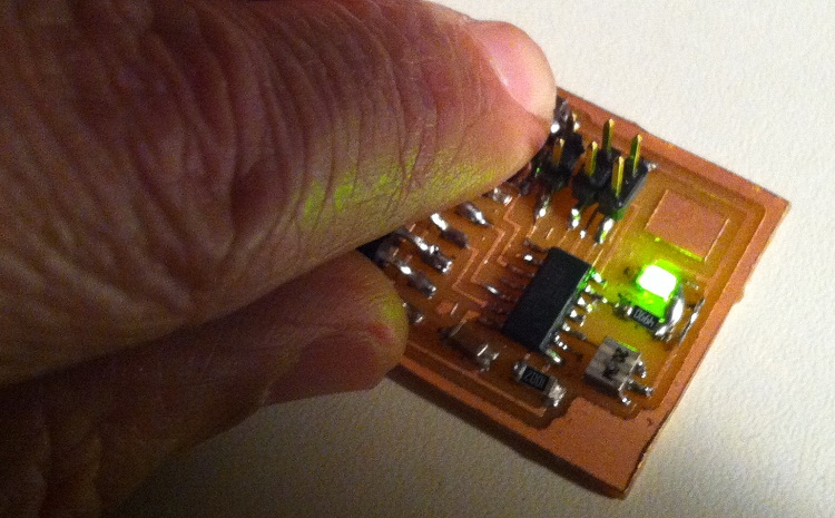
The production is amazing, in a matter of an hour and a half we had three plates welded and in another half hour, all programs loaded, OLE!
It was the first week dedicated to electronic everything we wanted to do worked, remains to me to learn to do the programs in both C and Python, but I'm on my way.
Board to Board, we use the file. C and "makefile" specific to each board, using our AVRISP2 as a programmer. Hello.temp.45, the first board works perfectly. In hello.txrx.45 we detected welding failure in one leg of the micro, once resolved, compile and program, and after reading in python, perfect. The third board seemed to work, green LED on!! but we could not program the micro, we detected some faults in welds, and again, once resolved, everything flowed.
I repeat, this week I would like to gut the C code to learn how to make some changes, it would be perfect!
Week13. Outputs


Week14. Networking
For this week, the winer word is DEBUG!! and second RECYCLE!!!
I made the hello.bus.45 set. with three nodes.
Only one of the boards was programed without troubles, the others was debuged many times before to work.
In this electronic week, my idea was instal all the software needed to work in my laptop, running with Windows 7. Until now, I had not installed Python for example, and now work perfectly.
I followed the tutorials from Anna Kaziunas page, thank you Anna.
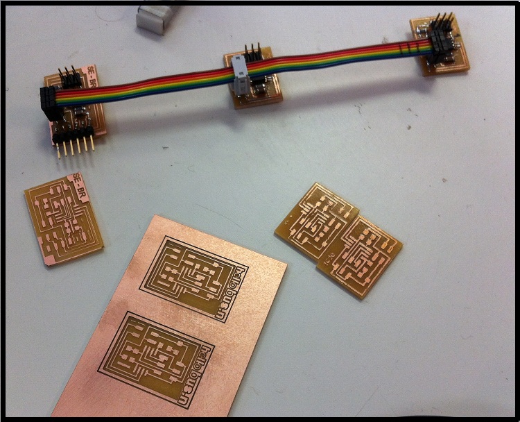
Like last week, I made the boards without using milling machine.
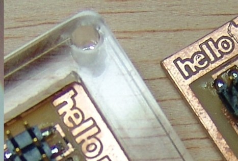
The chosen system was new, direct transfer from paper. I used sheets Press-
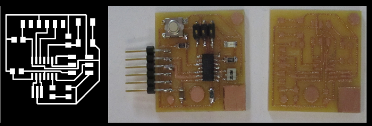
Not all the team worked with the transfer. Here you can see some Hello.nodes made by Jose Perez with our I-
I had prepared three boards, two Nodes and a Bridge, but my Bridge died in a hard debug session.
In this point of the Academy classes our electronic´s part stock is alarming, so we exploit all components of defective parts.
Following the Anna Tutorial for this week, the node was named like '0','1','2'. Here the Viemo link.
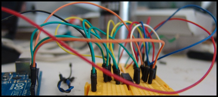
My favorite work for this week... the USB-
I was no sure if conecting the Bridge to the FTDI wire, and the Node with AVR , I could write something in the Bridge´s Micro, so I prepared a special conection with prototype wire from Arduino box.