Our group assignment this week was to:
 The Prusa i3 Mk3s
The values we ended up getting were:
We must point out the interesting result where once the button was pushed, our voltage increased on point B from 0.5 mv to 5 v
 Equation for spindal speed
Below is a picture of our group working with Proffesor Goodman on the oscilloscope. What we have up on screen is the actual binary code that our pcb was using to communicate. Using this technique is a good way to check if your board is actually working as this is denfinate proof that our chip is communicating with the computer.
 Equation for spindal speed
 Equation for spindal speed
Above is the diagram for the chip that we are using for this week. Our lab decided to use the ATtiny 1616 since the ATtiny 1614 chips that were ordered were backlogged on digikey
 Equation for spindal speed
I started out by using KiCad with the fabacademy libraries. Above I got each individual part and put it in my schematic. This schematic is a simple representation of our circuit, so it can be as ugly as I want it to be, I just need the connections for the next part of my process.
On my board I knew I needed:
What I am going to add is:
 Equation for spindal speed
I then exited Eeschema and converted my schematic in pcbnew. Below you can see the paths that I made. I manually routed my board, which some problems came about mainly because my Eeschema diagram was crowded. I used two layers: F.cu and Dwgs.user. I then could export these layers into SVG files for my traces and outlines.
now that I have my svg files from KiCad I will use the software Mods in order to turn them into .rml files that my Roland SRM20 can read
This link is the website that was used in the following
When first opening up Mods it will ask you to right click in order to open the menuing. Doing this we first want to head to "Programs"
 Equation for spindal speed
Then we want to select "Open Server Program"
 Equation for spindal speed
Then we want to scroll all the way down to Roland > Mill > SRM-20 > PCB svg. These are the specifications that I used but as you can see there are multiple different Roland machines with different file formats that Mods can read. You can even convert a png into a .rml file if you really wanted to.
 Equation for spindal speed
The first this that you are gonna want to do is to left click and head on over to Modules > Sevre Modules > file > save. I'm am doing this here as my computer is not hooked directly up to the roland so I want my files saved onto my computer.
 Equation for spindal speed
And below we can see exavtly where we want that hooked up to
 Equation for spindal speed
Next we can select the svg file that we wish to converted into a .rml file and contine from there. The next two boxes are really important so we need to make sure that our setting our correct. On the first box we need to see if our file needs to be inverted or not. This is normally a case by case situation but if you are coming from KiCad then it will need to be inverted. Next we need to make sure that that we select the correct option between "mill traces" and "mill outline." These setting will be changing our tool diameter, cut depth, and max depth.
 Equation for spindal speed
Next in this section, we need to make sure that for x, y, and z origin are all set to zero. as you can see from the image they are set to ten initialy. Double check that jog hight is reasonable, and that the z of home is greater than zero. For our traces a good speed will be 4, but for our outline we will want to lower it to around 0.5
 Equation for spindal speed
Next we can hit calculate and this will generate our rml file for us. It is good practice to check the preview that is given as well as giving a quick look over of you rml file just incase
 Equation for spindal speed
Below you can see the general menu that we will be using while operating the Roland.
 Equation for spindal speed
One of the first things you want to check is that under the menue belwo that we have "User Coordinate System" selected as, if you don't, the Roland is going to try to mill your traces far away from where you want it. I had this problem occur for me and I was annoyed at how simple the solution was.
 Equation for spindal speed
Setting the zero for the x/y is easy, hust use the arrow keys in the roland interface and select the "x/y" button under the "Set Origin Point" section. For the z axis we will have to get a little more creative. Initialy when we put our bit in we want to put it farther up than it normally should be so that we can lower it then release it to rest on our copper. Video can e seen below.
This is actually a terrible system and it is incomprehensible how the Roland doesn't have any automatic z mapping built in as the most problems I had involved the Roland not cutting the traces correctly as the surface of the Roland was not flat.
Last thing to check before running the Roland is to make sure in the "Setup" menue that you have the correct command set selected. In my case I could select either the top or bottom option as i'm using rml
 Equation for spindal speed
 Equation for spindal speed
Above you can see my traces that I cut my traces with my Roland mill at my lab.
 Equation for spindal speed
 Equation for spindal speed
Above you can see my board, most of the sodering was the same as the electronic production week with the exception of the pins. I used soder paste for most of my components but for the pins I used an iron.
 Equation for spindal speed
I ended up having two problems. In my haste to finish the assignment and working with not a lot of sleep, I first routed my button to the wrong side of the capacitor and I pathed the wrong pins to RXD and TXD. One problem, the capacitor, I fixed by jumping with a copper wire, but I have yet to fix the RXD and TXD problem.
 Equation for spindal speed
Next I needed to code my board in Arduino, the first step is the connect my board to my computer by Usb making sure the VCC is correctly aligned as seen below.
 Equation for spindal speed
Next, in the arduino IDE, we go to Open File / Preferences and and we want to go down to Additional Board Manager URLs and add the URL to get megaTinyCore
The URL I used was:
 Equation for spindal speed
Next we need to go to, Tools / Board and select Boards Manager. Here we need to find megaTinyCore and install the package
 Equation for spindal speed
Next we need to go back to tools and make sure that in the Borad menu that we have our chip selected, in my case ATtiny 1616. We also need the Programmer menu to be selected as Serial port and 4.7k (pyupdi style)
 Equation for spindal speed
Next we need to load up echo.ino in sketch and select "upload using programmer", after this we should hope that our code compiles to our board with no errors
 Equation for spindal speed
Next we need to go to, Tools anf then Serial Moniter. My board didn't work so I will need to come and do this step later
The first steps I need to take was to re route my board in KiCad. This time I needed to make sure to route my lines correctly around the button, but the main thing to remember was that the RXD of my microcontroller will need to go to the TXD of my header pin, and vice versa. This cuased me great confusion when initialy designing my board and I hope to iron out this issue
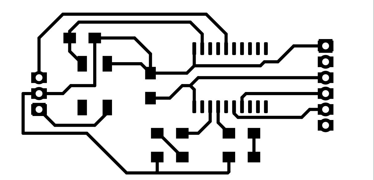
Below are new traces and schematic that actually ended up working. Wasn't too much of a pain to get this working as a I just needed TXD and RXD to work properly.
 Equation for spindal speed
 Equation for spindal speed
Now I just need to hook my code back up properly to the FTDI cable to that I can properly run the echo.ino code
 Equation for spindal speed
 Equation for spindal speed
Instillation seems to have worked.
 Equation for spindal speed
And much to my joy it actually works this time!!
Old Vector Files
Old RML Files
New Vector Files
New RML Files
Arduino File
KiCad Files