The first 3D CAD software I decided to check out was Fusion 360. I thought about checking out freeCAD but since my school has a license for Fusion I decided to give it a go.
 What you see when opening Fusion 360
When first opening up Fusion 360, you are greeted with this screen for your project. Although it may seem daunting, we can take things step by step. The gid area is where the majority of the work is going to be done and where your 3D model will take shape. The top nav bar is where the tools to create your design are housed.
 Navigate to this top bar
Taking a look at our nav bar, our tools are sorted in the sections called: solid, surface, sheetmetal, and tools. For my this design, i'm going to focus on the gagets in the solid section. Things are further sorted under in solids section but the main ones we will be focusing on are create, modify, and assemble. Under modify, we are first going to start out with a sketch (first option in modify).
 Drawing options
Once we are in sketch and select our desired plane we will now have some new set of tools. The above tools allows us to draw circles, lines, rectangles, and many more shapes in a variety of ways.
 Constraint options
Some more useful tools are the restraints bar. Restraints allow us to mark our geometrical characteristics between two or more entities creating relationships that the computer must follow. These include making objects horizontal, equal, parallel, tangent, and much more.
 Sketch with dimensions and constraint (to midpoint)
Above is what it looks like to sketch out an object in the working space. When sketching an object it is important to put constraints as well as sketch dimesions (option all the way to the right in create menu).
 Extruded sketch
Next I have selected to finish my sketch and selected the extrude option in the create section. I selected the outer circle to extrude 5mm and the inner circle to extrude 20mm giving me the shape above.
 Switch to the tool bar
My final project will need a couple gears in the design so I navigated over to the tools bar and selected the add-ins option.
 Select script then hit run
Above is the menu that pops up. What is shown is scripts that can create more complex objects than standard shapes. You can create your own, but Fusion as some pre-installed. Most of the scripts are written in python. I scrolled down and selected the Spur Gear.
 Option menu for gear
Above is the option menu for creating a spur gear. A thing to keep in mind, if you want to create a gear that is half the size of another, both the number of teeth and the root fillet radius will need to be halved.
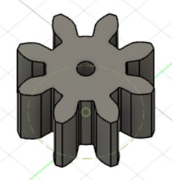 First gear I made
This is the result that is created. The dotted circle is the pitch diameter. For a gear to spin, the pitch diameter for both gears should be touching.
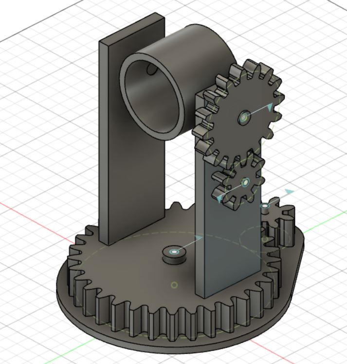 Final project
Finally, using all the tools given in Fusion 360, I created a mock model for my final project.
The other 3D CAD sowftware Idecided to check out was SolidWorks since most of my experience in CAD has been with SolidWorks.
 Navigate to this top bar
When first opening SolidWorks I was greeted with the screen above. We can choose to either create a part, assembly, or a drawing. We are going to start with a part and transition over to over to the other files during our process.
 Navigate to this top bar
Above is the main screen we will being doing the work on. Just like fusion 360 we have a place to the left where our objects are displayed and a tool bar on the top. There is generally more options staring you in the face here so it can be hard to navigate.
 Navigate to this top bar
Above, SolidWorks generally has all the same tools that were in Fusion 360 but in a different layout. Selecting the sketch button in the top left we can start our process just like in Fusion 360.
 Navigate to this top bar
Similar to Fusion 360 we must select a plane in which to sketch on normally selecting the top or front plane is good. If your part end up upside down it can be fixed in assembly.
 Navigate to this top bar
Starting sketch that I will revolve base
 Navigate to this top bar
Again the features bar resembles solid bar in Fusion 360. This tool bar contains extruding, cutting, filleting, and many other tools.
 Navigate to this top bar
When using tools in solidworks, this side bar has most of the general info and options. In this case i'm revolving base and need to select a line/point for my solid to pivot around.
 Navigate to this top bar
Once you have created multiple parts use can create an assembly file where you can combine them all into one. Here I have dragged out three different parts in order to create a pokeball.
 Navigate to this top bar
Above is a new tool bar in during assembly. The most important feature is the mate tool. Using this tool you can set up constraints to get parts in their desired locations.
 Navigate to this top bar
Above is the finished product. I have created a pokeball. Yay!
 Navigate to this top bar
SolidWorks gives you the ability to assign colors and materials to your different parts. This can make things look good but also has a affect on simulations.
 Navigate to this top bar
Here is a render of my pokeball.
 Navigate to this top bar
Above is the drawing file where you can show of each part and their dimesions in a more professional way.
In conclusion I like using both Fusion 360 and SolidWorks. It seems that both take a lot to master especially when things can be confusing with the amount of menuing that can be involved. In the end, even though I actually have more experiance with SolidWorks, i'm going to use Fusion 360 since I can access it on my labtop (SolidWorks is on a single computer in a lab) and it is also what I will be using in the future as a hobbyist.
Gimp is the main image editor that I gave been using, so i'm using it here. My goal is to extract the mushroom people out of the wallpaper I found below
 Navigate to this top bar
Above is a wallpaper I found for the game Dark Souls. My plan is to get a vector image of only the mushroom people.
 Navigate to this top bar
Above is the first tool I used the color selection tool.
 Navigate to this top bar
As you can see I cut away most of the backround leaving most of the characters remaining.
 Navigate to this top bar
Another tool I can use is the fuzzy select tool seen above.
 Navigate to this top bar
Image was not clean enough to completely cut out the mushroom people.
 Navigate to this top bar
Using the path tool I can manually make a path to clean my image.
 Path tool in action
 Navigate to this top bar
I was eventually able to isolate my image
Next I downloaded Inkscape in order to vectorize my image.
 Navigate to this top bar
Once my image was loaded in, I went to paths then trace bitmap...
 Navigate to this top bar
Here is all the options that was offered to me, the preview of my image can also be seen in the window on the right hand side. I hit "OK" to proceed.
 Navigate to this top bar
Above is my final result.
Vector file from Inkscape mushroom.svg
Clean file of image mushroom_rastor.jpg
SolidWorks parts:
Fusion 360: