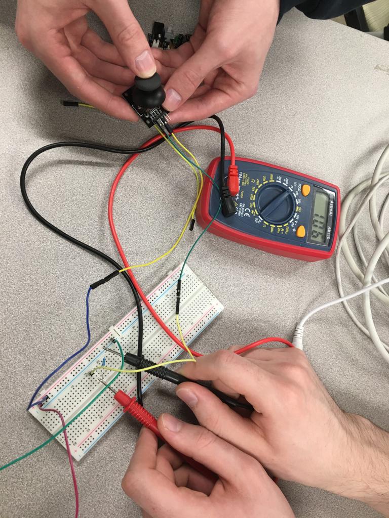
The group section began with our very own Prof. Goodman giving us a demo about many of the different input devices. The main goal to reach for this weeks group assignment was to probe an input device's analog levels and digital signals.
One of the first devices we looked at as a group was a photoresitor. Below you can see that we have the photoresitor set up while we measure the voltage across the pulldown resistor. You can see the value will change depending on whether we have a hand over the photoresitor or not.
 photoresitor with no hand over it
 photoresitor with hand over it
The next one we measured was the joystick. A joystick is basically two potentiometer and a button. Again, when we measured the voltage difference across the pulldown resistor, the value will change depending on whether the joystick is in a neutral position, or whether we have pushed it to either side or not.
 Joystick in neutral position
 Joystick being pushed backwards.
Another thing I tested out was making a quick design in tinkercad. below is that design. If you want to check it out with the code in hand go here.
 Arduino setup in tinkercad
Next was the individual assignment. Here, since one of my final projects included shooting of rockets, I wanted to test out using an accelerometer so that I would have some experience with it in the future.
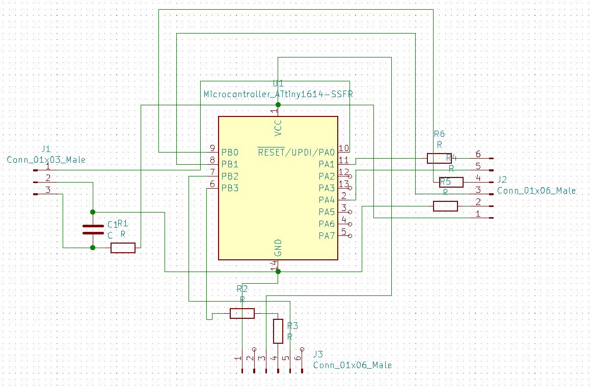
I started out by making some designs in Kicad, the schematic can be seen below. I have three pins for programming, six so that I can communicate with serial, and six additional pins for the accelerometer. The necessary capacitor bewtween ground and vcc has also been included.
 Equation for spindal speed
Next you can see how I routed the board. This board was quite hard to route and I ended up having to jump a couple of things as some connections like UPDI are in really hard places to get to and since ground and vcc are in opposite positions they end up cutting a lot of things off.
Another thing to note is this time around I am using an ATtiny 1614 as the 1616s we had have all run out. This means I have less pins to work with but I still had enough.
 Equation for spindal speed
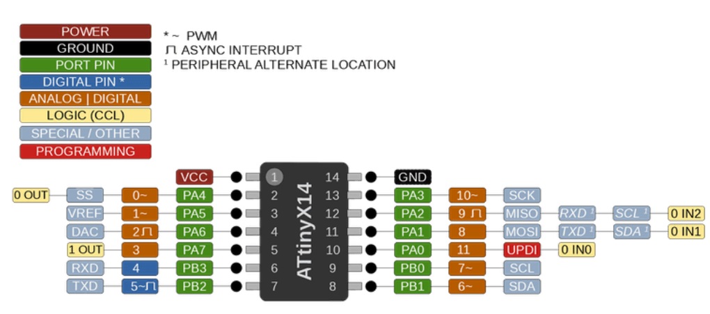
Here is the pinout diagram for the 1614. The only new things that I need to worry about that I haven't really used before are the SDA and SCL connections which are on pins eight and nine respectivley.
 Equation for spindal speed
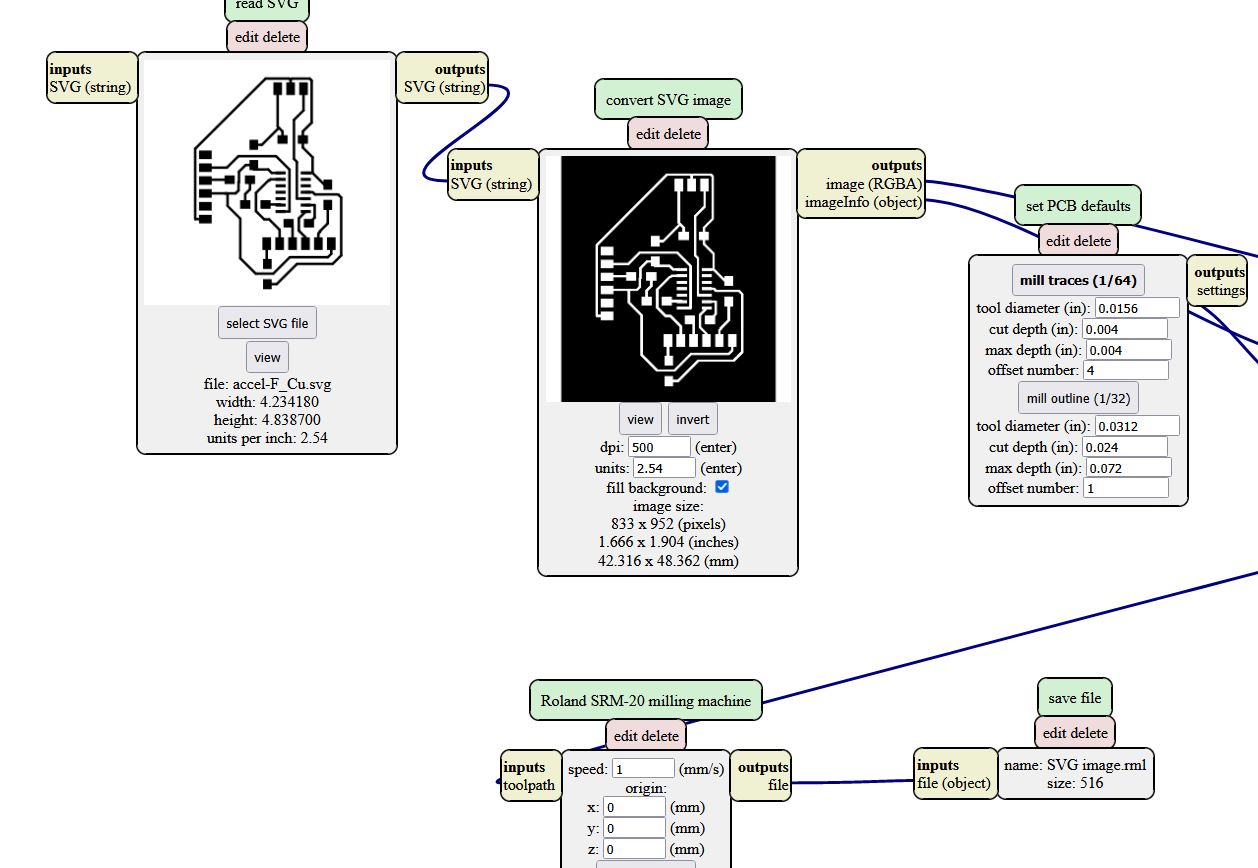
I then ran these designs though mods so that I could start milling them.S
 Equation for spindal speed
Here is the exact pinout of the accelerometer I was trying to use. VIN, GND, SDA, and SDL all have specific pins that they need to be connected to while SDO, CS, INT 1, and INT 2 can be connected to any valid pins.
 Equation for spindal speed
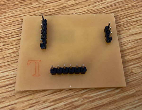
Pins were sodered into the sockets of the accelerometer and for the time being, as im ordering my own eventually for the final project, im going to use dupont cables for connections.
 Equation for spindal speed
Pinout is also written on the back of the accelerometer so as to not get confused while setting it up.
 Equation for spindal speed
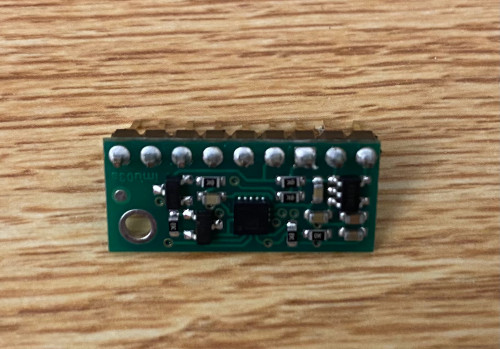
After milling and sodering my board this is how it came out. I actually haven't been having as much trouble as other people in class in making these boards but I did end up having a problem. I somehow fried the microcontroller on the board, I think it ended up happening when I pulled the power out prematurely. Normally the capacitor on the board should help stop this from shorting the board, but I guess I had some bad luck.
 Equation for spindal speed
I designed this board with through holes as you can see, I normally design all of my boards with through holes as I think they are easier to soder on then surface mounted pins.
 Equation for spindal speed
I was programming my board and it was working but sadley I neglected to take pictures of anything before my board met its untimeley end.
 Equation for spindal speed
Here is the message I was receiving which basically means that my board was shorted which really annoyed me.