Week 13 Networking and Communications
Welcome to this page about networking and communications! In the summary below, you can jump directly to topics.
Summary
A network should always contain more than two devices that talk with each other. This week, we will learn how to program and distinguish the signals from multiple devices.
Assignments
Group project:
- Send a message between two projects
Individual project:
- design, build, and connect wired or wireless node(s) with network or bus addresses
Learning outcomes:
- Demonstrate workflows used in network design
- Implement and interpret networking protocols and/or communication protocols
Project management
This week’s planning:
| Spiral | Tasks | Time |
|---|---|---|
| 1 | Group assignment | 8 hours |
| 2 | Design PCB schematics | 8 hours |
| 3 | Mill PCB board | 2 hours |
| 4 | Soldering PCB board | 1 hour |
| 5 | Programming the boards | 16 hours |
| 6 | Researching data sheets | 8 hours |
| 7 | Documentation | 8 hours |
Let’s get started!
This week’s results
Here is a video of a blinking LED, sent from a Student to a Teacher board.
The data transfer shown in the Serial Monitor.
Connecting an OLED over I2C with three different libraries: Adafruit_SSD1306/Adafruit_GFX, U8g8 and U8x8.
Networking and Communications
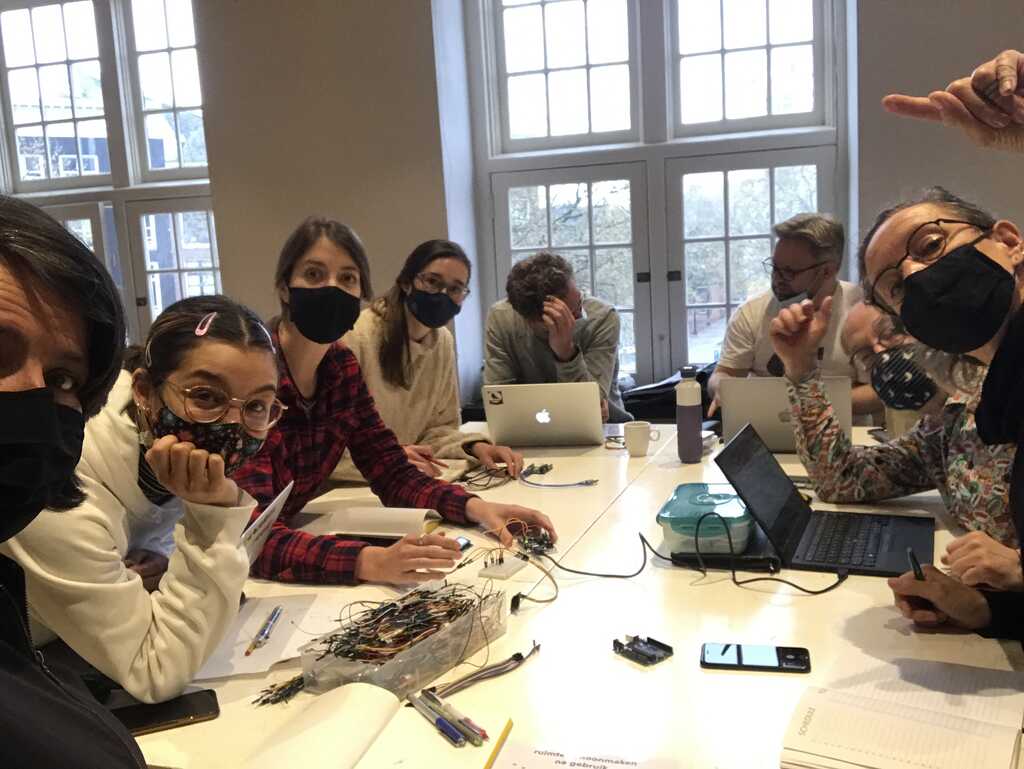
During local class on Thursday, Henk explained the difference between three communication methods: asynchronous serial, SPI and I2C.
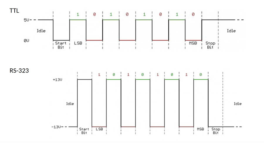
Asynchronous Serial means that data is transferred without support from an external clock signal. TX = Transmit and RX = Receive. This is what the schematics look like:
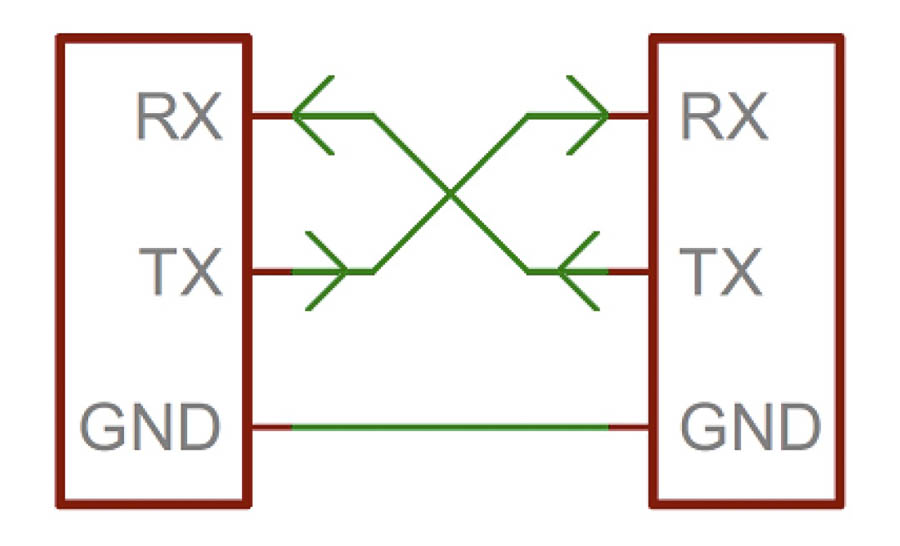
This is why we messed up TX and TY during the first week! Next, Henk explained what a parity bit is. This can be calculated to find out if the message arrived.
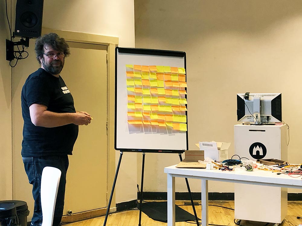
Start with 7 bits (sticky notes). 8 bits in a row address space, so 7 bits of data. The yellow and orange sticky notes represent ones and zeros.
- Rows: count 7 bits: even vs uneven. Add 1 or 0 in 8th column.
- Columns: repeat the process.
Parity bit = sticky note at the end of row that indicates if it’s an even or uneven row. It’s the 8th bit. The extra row below is only for the example at Waag.
LSB = least significant bit MSB = most significant bit
We also learned what a Baud Rate exactly is. When opening the Serial Monitor in the Arduino IDE, you have to select a baud rate. This is how fast data is sent over a serial line: bps (bits per-second). “Standard” baud rates are: 1200, 2400, 4800, 19200, 38400, 57600, 115200.
In terms of time?
- 9600 bps -> 1/9600 = 104us
- 115200 bps -> 1/115200 = 8.7us
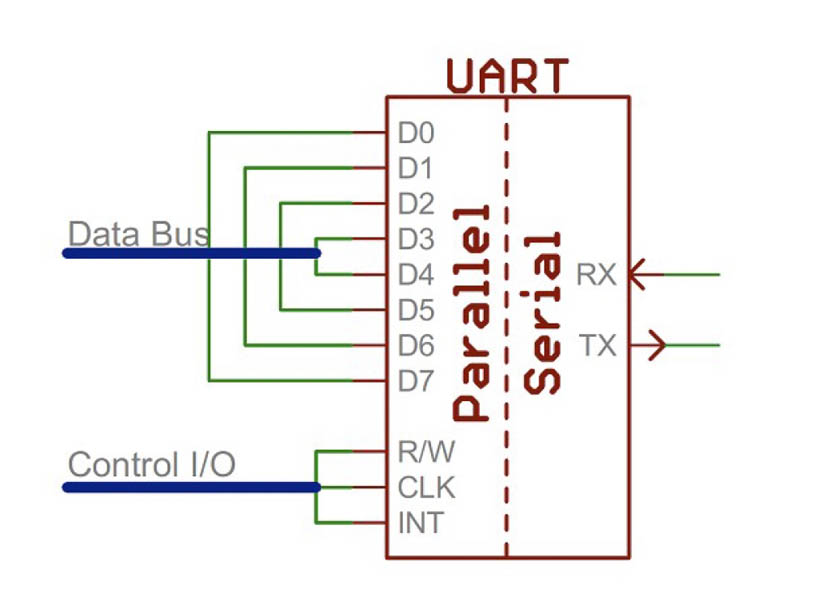
A universal asynchronous receiver/transmitter (UART) is a block of circuitry responsible for implementing serial communication. UART basics here.
Serial Peripheral Interface (SPI) is still used a lot, but ISPC is becoming more popular in recent years. You need more pins for SPI. It’s serial with clock data that keeps both sides in perfect sync. At least four cables.
I2C Those two wires can support up to 1008 peripheral devices. Basics of the I2C communication protocol can be found here.
Stopcondition: Once all the dataframes have been sent, the master will generate a stop condition. Stop conditions are defined by a 0->1(lowto high) transition on SDA after a transition on SCL, withSCL remaining high.
The libraries for I2C:
- Wire.h (it’s a big library)
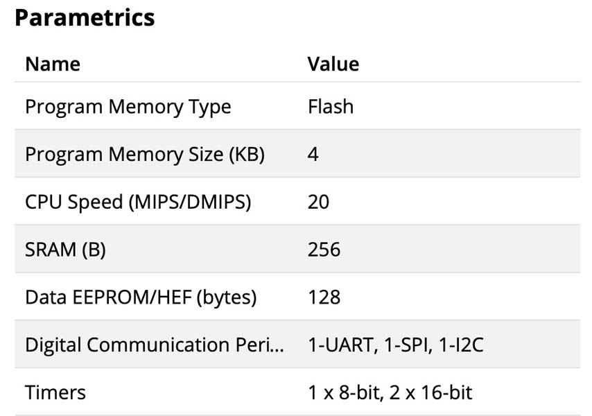
Good practice: think about what you want to make. What library do you need? How big is this library? Make a small program with all libraries included, compile it and see how big it is. Most space is needed by the libraries. Processor size limits what you can do. There are different types of memory. Which one to take? Let’s take an ATtiny412 as an example. Here is the product page: Program Memory Size (KB) - flash, SRAM or Data EEPROM/HEF (bytes)? Often, it’s the Flash program memory size.
Group assignment
As a group, we had two tasks:
- Serial Communication with two Arduino’s
- ISPC with at least two displays
We documented our group process and results at the Waag group page. It was very special to do this together, for the first time since the start of Fab Academy!
Making the boards
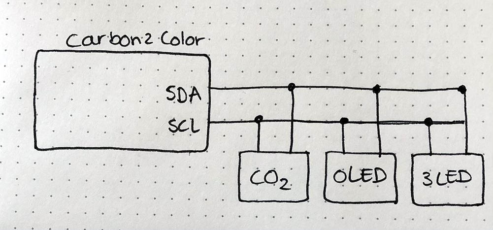
This week I choose to focus on an I2C connection, because that’s also what the OLED monitor and CO2 sensor board uses. It communicates on two pins: SDA (serial data) and SCL (serial clock). Last week in Output Devices, I already designed a board with I2C connection for the OLED and CO2 sensor. Therefore, I’m recycling that board for this week’s assignment. It’s going to be the master board. The sensor and OLED are two nodes, and I will design and mill a third node with three LEDs on it.
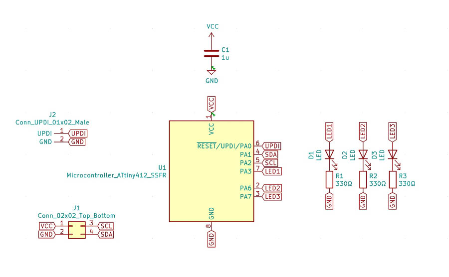
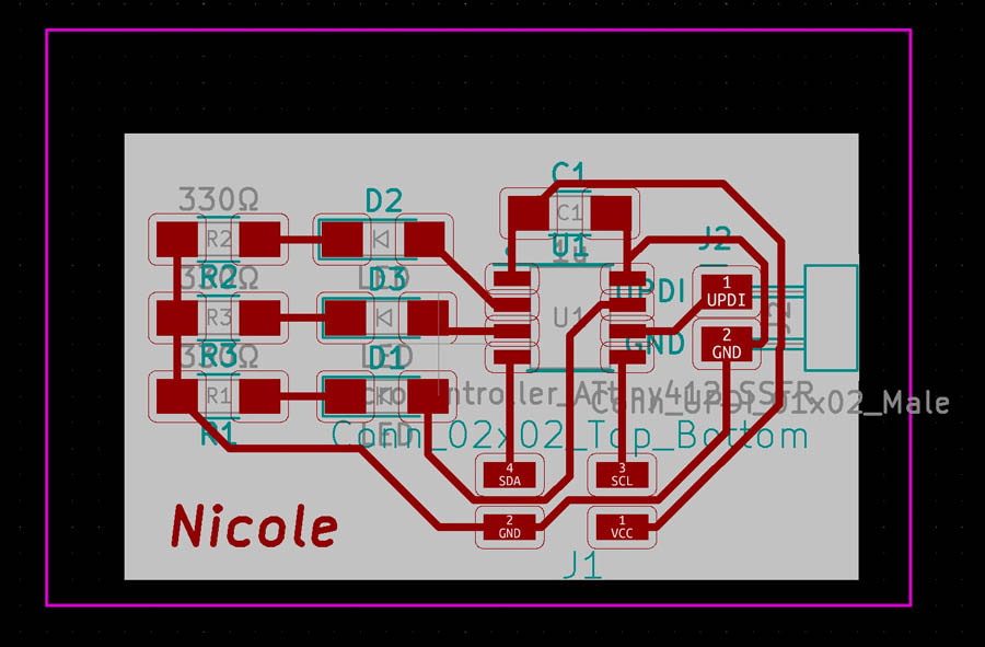
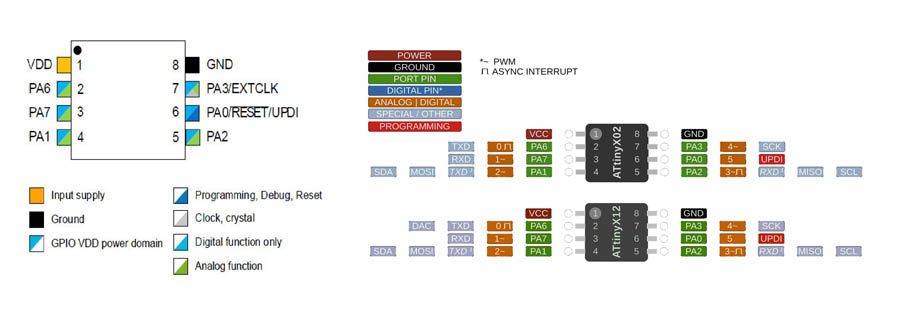
The example board from Neil: Hello I2C on ATtiny1614 is an example. In KiCad’s Eeschema, I started with designing the third node with the three LEDs. Because I need less pins, I decided to go for an ATtiny412.
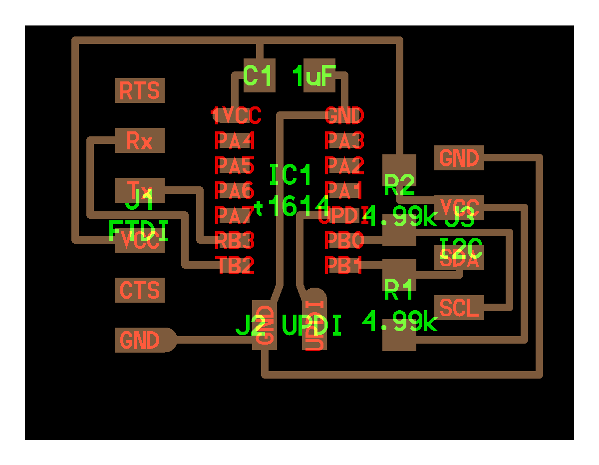
After that, I created the traces in the PCB Editor.
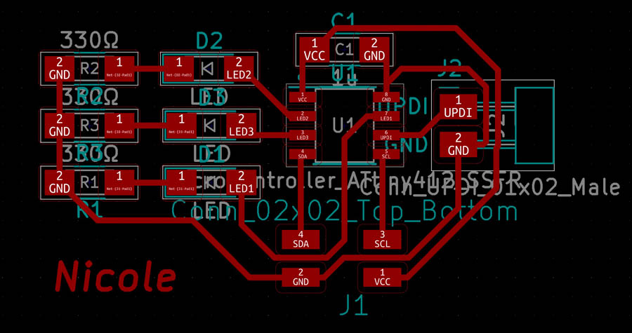
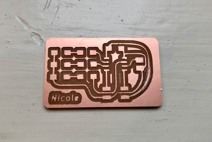
And added an outline and Margin.
Here is the board after milling.
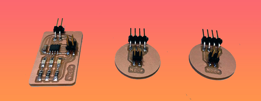
Next, I thought it’d be nice to create two nodes for the CO2 sensor and OLED. This way, it is possible to connect them in a row with a flat cable. Here is the Eeschema:
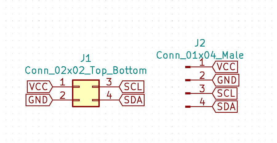
And the design in the PCB Editor.
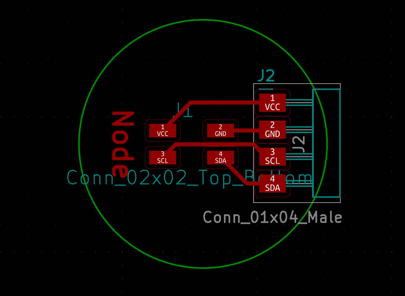
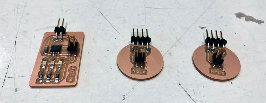
The nodes after milling.
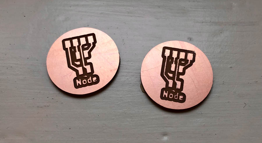
And here are the boards after soldering.
Node 1: OLED
To get the OLED working on my board, I consulted Adrian’s page. First, find out the I2C number with the I2C scanner provided by Neil.
//
// hello.I2C.ino
//
// I2C hello-world scanner
//
// Neil Gershenfeld 12/8/19
//
// This work may be reproduced, modified, distributed,
// performed, and displayed for any purpose, but must
// acknowledge this project. Copyright is retained and
// must be preserved. The work is provided as is; no
// warranty is provided, and users accept all liability.
//

#include <Wire.h>

void setup() {
   Serial.begin(115200);
   Wire.begin();
   }

uint8_t address,count;

void loop() {
   count = 0;
   Serial.println("start scan ...");
   for (address = 1; address < 127; address++) {
      Wire.beginTransmission (address);
      if (Wire.endTransmission () == 0) {
         count += 1;
         Serial.print("   found ");
         Serial.print(address,DEC);
         Serial.print(" (0x");
         Serial.print(address,HEX);
         Serial.println (")");
         }
      }
   if (count == 0)
      Serial.println("   no devices found");
   delay(1000);
   }
Here is a screenshot of the I2C hello-world scanner.
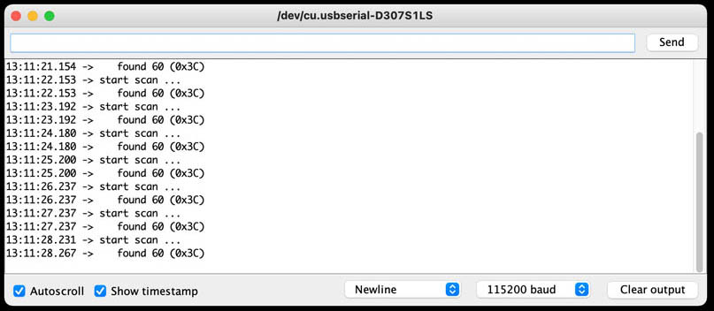
The scan that’s found is 60 03xC.
Now continue with a simple Hello OLED program:
/*********
  Rui Santos
  Complete project details at https://randomnerdtutorials.com
*********/
//Fab Academy 2020 - Fab Lab León
//OLED
//Adrianino
//ATtiny1614

#include <Wire.h>
#include <Adafruit_GFX.h>
#include <Adafruit_SSD1306.h>

#define SCREEN_WIDTH 128 // OLED display width, in pixels
#define SCREEN_HEIGHT 64 // OLED display height, in pixels

// Declaration for an SSD1306 display connected to I2C (SDA, SCL pins)
Adafruit_SSD1306 display(SCREEN_WIDTH, SCREEN_HEIGHT, &Wire, -1); // // Reset pin # (or -1 if sharing Arduino reset pin)

void setup() {
  Serial.begin(115200);

  if(!display.begin(SSD1306_SWITCHCAPVCC, 0x3C)) { // Address 0x3C for 128x64
    Serial.println(F("SSD1306 allocation failed"));
    for(;;);
  }
  delay(2000);
  display.clearDisplay();

  display.setTextSize(1);
  display.setTextColor(WHITE);
  display.setCursor(0, 5);
  // Display static text
  display.println("Hello, world!");
  display.setCursor(0, 20);
  display.println("Fab Academy 2020");
  display.println("Carbon2Color");
  display.println("Nicole Bakker");
  display.display();
}

void loop() {

}
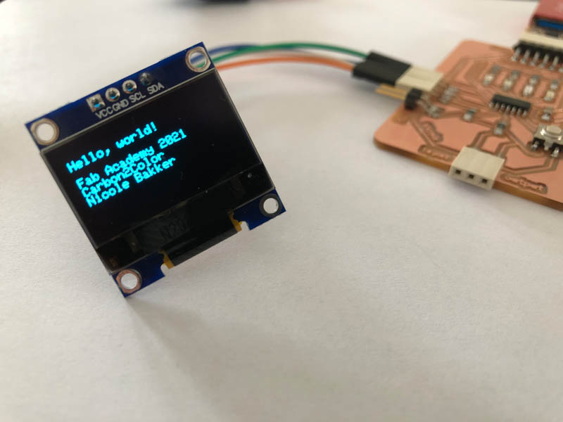
Here you can see the working OLED :)
And with the node.
To program the OLED to do cooler stuff, here is a guide from Random Nerd Tutorials.
Node 2: CO2 sensor
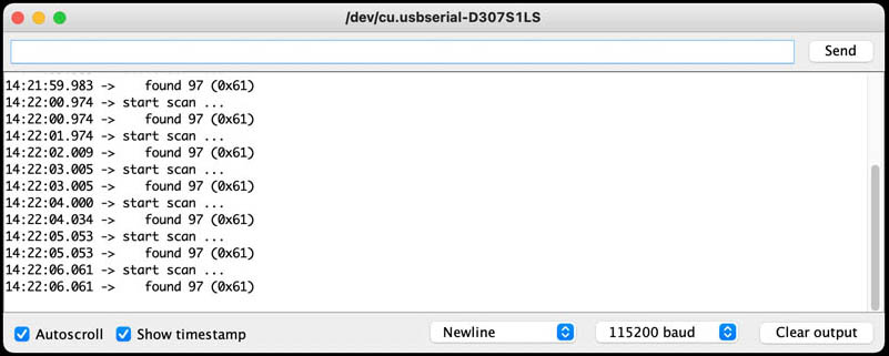
The I2C of the CO2 sensor was working last week during output devices. The I2C scanner for the CO2 sensor shows that the ID is: 0x61.
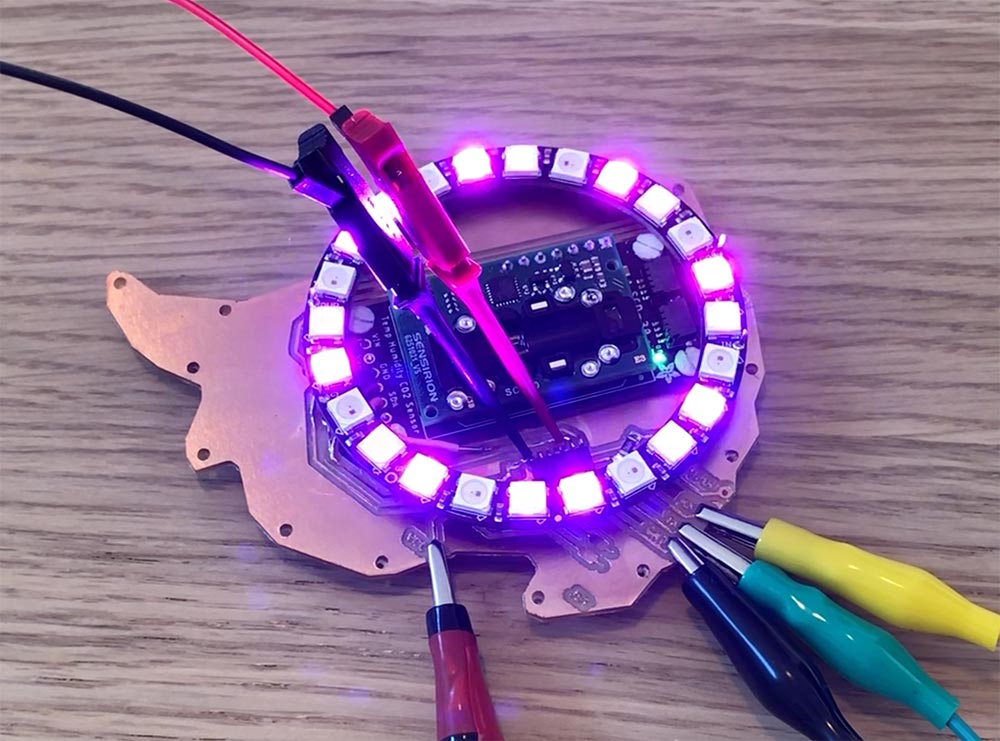
Node 3: LED board
To power this LED board I connected it to the VCC and GND of the Carbon2Color board.
Here is the code to test if the board works:
int LED1 = A6;
int LED2 = A7;
int LED3 = A3;


void setup() {
pinMode (LED1, OUTPUT);
pinMode(LED2,OUTPUT);
pinMode(LED3,OUTPUT);
}

void loop() {

// LED1 = red
{
   digitalWrite(LED1,HIGH);
   delay(100);
   digitalWrite(LED1,LOW);
   delay(100);
   }


// LED2 = orange
{
   digitalWrite(LED2,HIGH);
   delay(100);
   digitalWrite(LED2,LOW);
   delay(100);
   }


// LED3 = green
{
   digitalWrite(LED3,HIGH);
   delay(500);
   digitalWrite(LED3,LOW);
   delay(500);
   }

}
Video of working board:
Now let’s see if we can connect the SDA and SCL. It seems like the scanning program doesn’t work on the ATtiny series. Both on the ATtiny412 and ATtiny1614 it basically gives back all addresses.
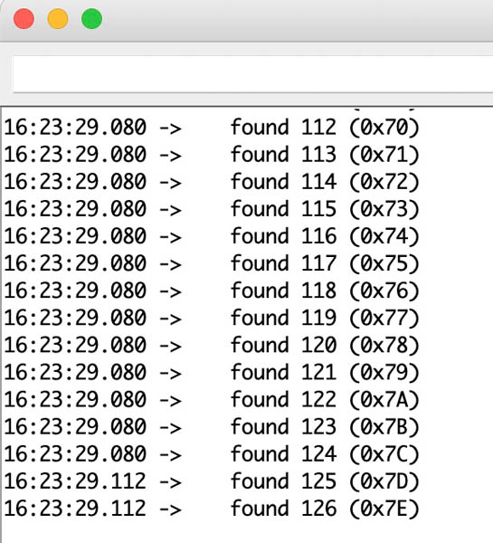
Here is the full list:
16:23:39.744 ->    found 1 (0x1)
16:23:39.744 ->    found 2 (0x2)
16:23:39.744 ->    found 3 (0x3)
16:23:39.744 ->    found 4 (0x4)
16:23:39.744 ->    found 5 (0x5)
16:23:39.744 ->    found 6 (0x6)
16:23:39.744 ->    found 7 (0x7)
16:23:39.744 ->    found 8 (0x8)
16:23:39.744 ->    found 9 (0x9)
16:23:39.744 ->    found 10 (0xA)
16:23:39.744 ->    found 11 (0xB)
16:23:39.744 ->    found 12 (0xC)
16:23:39.744 ->    found 13 (0xD)
16:23:39.778 ->    found 14 (0xE)
16:23:39.778 ->    found 15 (0xF)
16:23:39.778 ->    found 16 (0x10)
16:23:39.778 ->    found 17 (0x11)
16:23:39.778 ->    found 18 (0x12)
16:23:39.778 ->    found 19 (0x13)
16:23:39.778 ->    found 20 (0x14)
16:23:39.778 ->    found 21 (0x15)
16:23:39.778 ->    found 22 (0x16)
16:23:39.778 ->    found 23 (0x17)
16:23:39.778 ->    found 24 (0x18)
16:23:39.778 ->    found 25 (0x19)
16:23:39.778 ->    found 26 (0x1A)
16:23:39.778 ->    found 27 (0x1B)
16:23:39.778 ->    found 28 (0x1C)
16:23:39.778 ->    found 29 (0x1D)
16:23:39.778 ->    found 30 (0x1E)
16:23:39.778 ->    found 31 (0x1F)
16:23:39.778 ->    found 32 (0x20)
16:23:39.820 ->    found 33 (0x21)
16:23:39.820 ->    found 34 (0x22)
16:23:39.820 ->    found 35 (0x23)
16:23:39.820 ->    found 36 (0x24)
16:23:39.820 ->    found 37 (0x25)
16:23:39.820 ->    found 38 (0x26)
16:23:39.820 ->    found 39 (0x27)
16:23:39.820 ->    found 40 (0x28)
16:23:39.820 ->    found 41 (0x29)
16:23:39.820 ->    found 42 (0x2A)
16:23:39.820 ->    found 43 (0x2B)
16:23:39.820 ->    found 44 (0x2C)
16:23:39.820 ->    found 45 (0x2D)
16:23:39.820 ->    found 46 (0x2E)
16:23:39.820 ->    found 47 (0x2F)
16:23:39.820 ->    found 48 (0x30)
16:23:39.820 ->    found 49 (0x31)
16:23:39.820 ->    found 50 (0x32)
16:23:39.820 ->    found 51 (0x33)
16:23:39.820 ->    found 52 (0x34)
16:23:39.820 ->    found 53 (0x35)
16:23:39.820 ->    found 54 (0x36)
16:23:39.820 ->    found 55 (0x37)
16:23:39.820 ->    found 56 (0x38)
16:23:39.820 ->    found 57 (0x39)
16:23:39.854 ->    found 58 (0x3A)
16:23:39.854 ->    found 59 (0x3B)
16:23:39.854 ->    found 60 (0x3C)
16:23:39.854 ->    found 61 (0x3D)
16:23:39.854 ->    found 62 (0x3E)
16:23:39.854 ->    found 63 (0x3F)
16:23:39.854 ->    found 64 (0x40)
16:23:39.854 ->    found 65 (0x41)
16:23:39.854 ->    found 66 (0x42)
16:23:39.854 ->    found 67 (0x43)
16:23:39.854 ->    found 68 (0x44)
16:23:39.854 ->    found 69 (0x45)
16:23:39.854 ->    found 70 (0x46)
16:23:39.854 ->    found 71 (0x47)
16:23:39.854 ->    found 72 (0x48)
16:23:39.854 ->    found 73 (0x49)
16:23:39.854 ->    found 74 (0x4A)
16:23:39.854 ->    found 75 (0x4B)
16:23:39.886 ->    found 76 (0x4C)
16:23:39.886 ->    found 77 (0x4D)
16:23:39.886 ->    found 78 (0x4E)
16:23:39.886 ->    found 79 (0x4F)
16:23:39.886 ->    found 80 (0x50)
16:23:39.886 ->    found 81 (0x51)
16:23:39.886 ->    found 82 (0x52)
16:23:39.886 ->    found 83 (0x53)
16:23:39.886 ->    found 84 (0x54)
16:23:39.886 ->    found 85 (0x55)
16:23:39.886 ->    found 86 (0x56)
16:23:39.886 ->    found 87 (0x57)
16:23:39.886 ->    found 88 (0x58)
16:23:39.886 ->    found 89 (0x59)
16:23:39.886 ->    found 90 (0x5A)
16:23:39.886 ->    found 91 (0x5B)
16:23:39.886 ->    found 92 (0x5C)
16:23:39.886 ->    found 93 (0x5D)
16:23:39.886 ->    found 94 (0x5E)
16:23:39.923 ->    found 95 (0x5F)
16:23:39.923 ->    found 96 (0x60)
16:23:39.923 ->    found 97 (0x61)
16:23:39.923 ->    found 98 (0x62)
16:23:39.923 ->    found 99 (0x63)
16:23:39.923 ->    found 100 (0x64)
16:23:39.923 ->    found 101 (0x65)
16:23:39.923 ->    found 102 (0x66)
16:23:39.923 ->    found 103 (0x67)
16:23:39.923 ->    found 104 (0x68)
16:23:39.923 ->    found 105 (0x69)
16:23:39.923 ->    found 106 (0x6A)
16:23:39.923 ->    found 107 (0x6B)
16:23:39.923 ->    found 108 (0x6C)
16:23:39.923 ->    found 109 (0x6D)
16:23:39.923 ->    found 110 (0x6E)
16:23:39.923 ->    found 111 (0x6F)
16:23:39.923 ->    found 112 (0x70)
16:23:39.923 ->    found 113 (0x71)
16:23:39.923 ->    found 114 (0x72)
16:23:39.923 ->    found 115 (0x73)
16:23:39.959 ->    found 116 (0x74)
16:23:39.959 ->    found 117 (0x75)
16:23:39.959 ->    found 118 (0x76)
16:23:39.959 ->    found 119 (0x77)
16:23:39.959 ->    found 120 (0x78)
16:23:39.959 ->    found 121 (0x79)
16:23:39.959 ->    found 122 (0x7A)
16:23:39.959 ->    found 123 (0x7B)
16:23:39.959 ->    found 124 (0x7C)
16:23:39.959 ->    found 125 (0x7D)
16:23:39.959 ->    found 126 (0x7E)
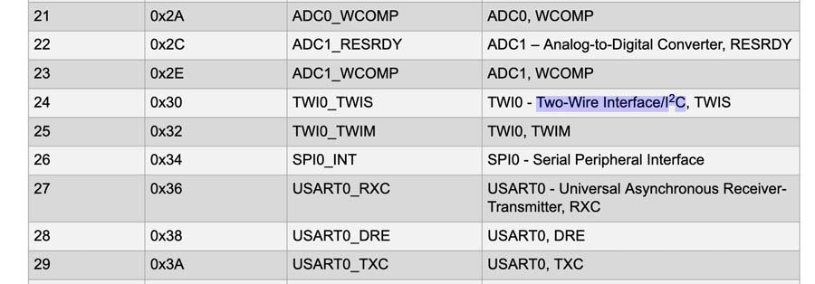
To find out what is going on, I started with an ATtiny1614 data sheet search to I2C address. On page 46 a hopeful table is provided. Showing 0x30 as a number.
Page 364 touches upon General TWI Bus Concepts. The TWI provides a simple, bidirectional, two-wire communication bus consisting of:
- Serial Data Line (SDA) for packet transfer
- Serial Clock Line (SCL) for the bus clockThe two lines are open-collector lines (wired-AND).
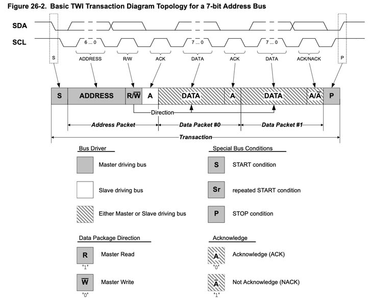
The TWI bus topology is a simple and efficient method of interconnecting multiple devices on a serial bus. A device connected to the bus can be a teacher or a student. Only teacher devices can control the bus and the bus communication. A unique address is assigned to each student device connected to the bus, and the teacher will use it to control the student and initiate a transaction. Several teachers can be connected to the same bus. This is called a multi-teacher environment. An arbitration mechanism is provided for resolving bus ownership among teachers, since only one teacher device may own the bus at any given time. A teacher indicates the start of a transaction by issuing a Start condition (S) on the bus. The teacher provides the clock signal for the transaction. An address packet with a 7-bit student address (ADDRESS) and a direction bit, representing whether the teacher wishes to read or write data (R/W), are then sent. The addressed I2C student will then acknowledge (ACK) the address, and data packet transactions can begin. Every 9-bit data packet consists of eight data bits followed by a 1-bit reply indicating whether the data was acknowledged or not by the receiver. After all the data packets (DATA) are transferred, the teacher issues a Stop condition (P) on the bus to end the transaction.
The following diagram is provided:
And on page 375 more information is provided in the Register Summary.
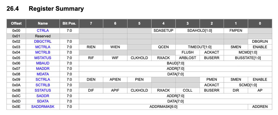
That’s all the information provided about I2C in the datasheet. Not much I would say! And I still don’t know why the scanner is giving back all IDs.
The network
The I2C network that brings all three nodes together. Here is a list of I2C addresses of the most common sensors and actuators. And here is an intro on I2C on Instructables.
In the previous sections I found two, maybe three ID’s:
- Node 1: CO2
0x61 - Node 2: OLED
03xC - Node 3: ATtiny412 with LEDs
0x30?
I’m not sure if the ID of the LED board is correct yet.
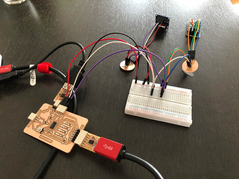
Combining nodes 1 and 2: CO2 sensor and OLED
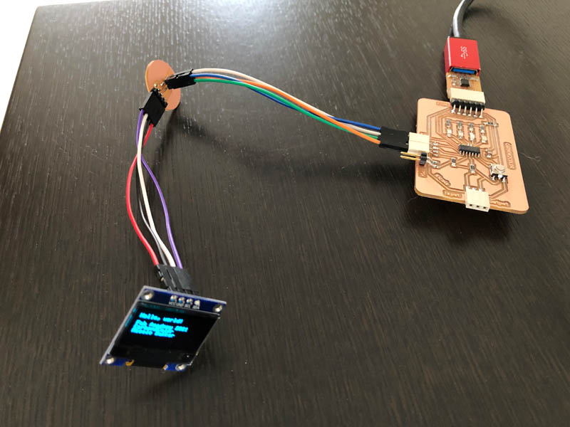
My first objective is to show the CO2-values on the OLED display. The fablab ran out of flat cables and connectors so I made this with a breadboard. Here is the setup:
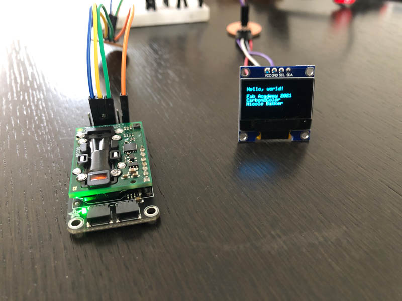
And below you can see the active sensor and the OLED. First spiral done!
The two programs work individually, however if I combine them in one sketch there is a compiling error:
Arduino: 1.8.13 (Mac OS X), Board:
/Users/nicolebakker/Library/Arduino15/packages/DxCore/tools/avr-gcc/7.3.0-atmel3.6.1-azduino3/bin/../lib/gcc/avr/7.3.0/../../../../avr/bin/ld: address 0x4aac of Carbon2Color_networking_CO2_OLED.ino.elf section `.text' is not within region `text'
/Users/nicolebakker/Library/Arduino15/packages/DxCore/tools/avr-gcc/7.3.0-atmel3.6.1-azduino3/bin/../lib/gcc/avr/7.3.0/../../../../avr/bin/ld: Carbon2Color_networking_CO2_OLED.ino.elf section `.rodata' will not fit in region `text'
/Users/nicolebakker/Library/Arduino15/packages/DxCore/tools/avr-gcc/7.3.0-atmel3.6.1-azduino3/bin/../lib/gcc/avr/7.3.0/../../../../avr/bin/ld: address 0x4aac of Carbon2Color_networking_CO2_OLED.ino.elf section `.text' is not within region `text'
/Users/nicolebakker/Library/Arduino15/packages/DxCore/tools/avr-gcc/7.3.0-atmel3.6.1-azduino3/bin/../lib/gcc/avr/7.3.0/../../../../avr/bin/ld: region `text' overflowed by 3244 bytes
So it looks like the sketch is too large for the microcontroller. Here are the sizes of the sketches:
- OLED: Sketch uses 15053 bytes (91%) of program storage space. Maximum is 16384 bytes. Global variables use 309 bytes (15%) of dynamic memory, leaving 1739 bytes for local variables. Maximum is 2048 bytes.
- CO2 sensor: Sketch uses 8854 bytes (54%) of program storage space. Maximum is 16384 bytes. Global variables use 303 bytes (14%) of dynamic memory, leaving 1745 bytes for local variables. Maximum is 2048 bytes.
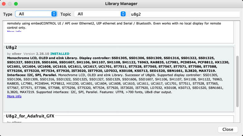
Indeed, that’s the issue. I think I’ll need a larger ATtiny to be able to run both programs! With this new information I contacted Henk and he came with another - even better - solution. It turns out there are other libraries for OLEDs that require much less memory. <Adafruit_SSD1306.h> and the <Adafruit_GFX.h> graphic libary are a big ones, and there are alternatives: the u8g2 by Olikraus. There are two systems to choose from: the U8g2 an U8x8. A comparison:
U8g2
- Includes all graphics procedures (line/box/circle draw).
- Supports many fonts. (Almost) no restriction on the font height.
- Requires some memory in the microcontroller to render the display.
U8x8
- Text output only (character) device.
- Only fonts allowed with fixed size per character (8x8 pixel).
- Writes directly to the display. No buffer in the microcontroller required.
To find out how they compare in terms of memory and functionality, I tested both Hello World example files. To do so, I first had to install the libraries.
Next, open the Hello World example sketch and figure out what type of OLED to uncomment in the massive list of ‘constructors’. A full overview of the constructor setup can be found on Github. After a lot of deciphering I decided to uncomment the following constructor line:
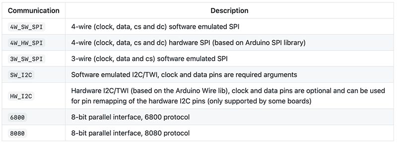
U8G2_SSD1306_128X64_NONAME_F_SW_I2C u8g2(U8G2_R0, /* clock=*/ SCL, /* data=*/ SDA, /* reset=*/ U8X8_PIN_NONE); // All Boards without Reset of the Display`
It is using I2C as the communication line, SW stands for software emulated I2C.
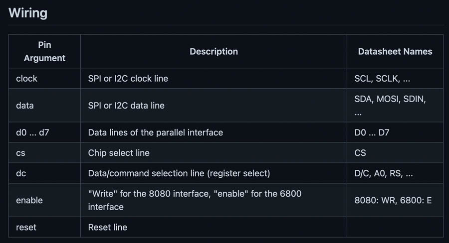
And here is guidance on wiring:
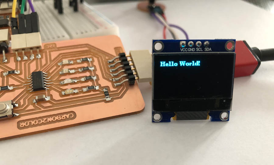
Testing the Hello World program of U8g2. On the display it looks like this:
Here is the code. For readability I removed all constructor lines that were commented.
/*

  HelloWorld.ino

  Universal 8bit Graphics Library (https://github.com/olikraus/u8g2/)

  Copyright (c) 2016, olikraus@gmail.com
  All rights reserved.

  Redistribution and use in source and binary forms, with or without modification,
  are permitted provided that the following conditions are met:

  * Redistributions of source code must retain the above copyright notice, this list
    of conditions and the following disclaimer.

  * Redistributions in binary form must reproduce the above copyright notice, this
    list of conditions and the following disclaimer in the documentation and/or other
    materials provided with the distribution.

  THIS SOFTWARE IS PROVIDED BY THE COPYRIGHT HOLDERS AND
  CONTRIBUTORS "AS IS" AND ANY EXPRESS OR IMPLIED WARRANTIES,
  INCLUDING, BUT NOT LIMITED TO, THE IMPLIED WARRANTIES OF
  MERCHANTABILITY AND FITNESS FOR A PARTICULAR PURPOSE ARE
  DISCLAIMED. IN NO EVENT SHALL THE COPYRIGHT HOLDER OR
  CONTRIBUTORS BE LIABLE FOR ANY DIRECT, INDIRECT, INCIDENTAL,
  SPECIAL, EXEMPLARY, OR CONSEQUENTIAL DAMAGES (INCLUDING, BUT
  NOT LIMITED TO, PROCUREMENT OF SUBSTITUTE GOODS OR SERVICES;
  LOSS OF USE, DATA, OR PROFITS; OR BUSINESS INTERRUPTION) HOWEVER
  CAUSED AND ON ANY THEORY OF LIABILITY, WHETHER IN CONTRACT,
  STRICT LIABILITY, OR TORT (INCLUDING NEGLIGENCE OR OTHERWISE)
  ARISING IN ANY WAY OUT OF THE USE OF THIS SOFTWARE, EVEN IF
  ADVISED OF THE POSSIBILITY OF SUCH DAMAGE.

*/

#include <Arduino.h>
#include <U8g2lib.h>

#ifdef U8X8_HAVE_HW_SPI
#include <SPI.h>
#endif
#ifdef U8X8_HAVE_HW_I2C
#include <Wire.h>
#endif

/*
  U8g2lib Example Overview:
    Frame Buffer Examples: clearBuffer/sendBuffer. Fast, but may not work with all Arduino boards because of RAM consumption
    Page Buffer Examples: firstPage/nextPage. Less RAM usage, should work with all Arduino boards.
    U8x8 Text Only Example: No RAM usage, direct communication with display controller. No graphics, 8x8 Text only.

*/

// Please UNCOMMENT one of the contructor lines below
// U8g2 Contructor List (Frame Buffer)
// The complete list is available here: https://github.com/olikraus/u8g2/wiki/u8g2setupcpp

U8G2_SSD1306_128X64_NONAME_F_SW_I2C u8g2(U8G2_R0, /* clock=*/ SCL, /* data=*/ SDA, /* reset=*/ U8X8_PIN_NONE);   // All Boards without Reset of the Display

void setup(void) {
  u8g2.begin();
}

void loop(void) {
  u8g2.clearBuffer();					// clear the internal memory
  u8g2.setFont(u8g2_font_ncenB08_tr);	// choose a suitable font
  u8g2.drawStr(0,10,"Hello World!");	// write something to the internal memory
  u8g2.sendBuffer();					// transfer internal memory to the display
  delay(1000);
}
I tested the Hello World example file of U8g2, this takes 53% of the memory.
Sketch uses 8685 bytes (53%) of program storage space. Maximum is 16384 bytes. Global variables use 1224 bytes (59%) of dynamic memory, leaving 824 bytes for local variables. Maximum is 2048 bytes.
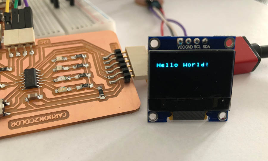
And this is what the Hello World sketch with U8x8 looks like:
Below is the code. Again, I removed all obsolete constructor lines.
/*

  HelloWorld.ino

  "Hello World" version for U8x8 API

  Universal 8bit Graphics Library (https://github.com/olikraus/u8g2/)

  Copyright (c) 2016, olikraus@gmail.com
  All rights reserved.

  Redistribution and use in source and binary forms, with or without modification,
  are permitted provided that the following conditions are met:

  * Redistributions of source code must retain the above copyright notice, this list
    of conditions and the following disclaimer.

  * Redistributions in binary form must reproduce the above copyright notice, this
    list of conditions and the following disclaimer in the documentation and/or other
    materials provided with the distribution.

  THIS SOFTWARE IS PROVIDED BY THE COPYRIGHT HOLDERS AND
  CONTRIBUTORS "AS IS" AND ANY EXPRESS OR IMPLIED WARRANTIES,
  INCLUDING, BUT NOT LIMITED TO, THE IMPLIED WARRANTIES OF
  MERCHANTABILITY AND FITNESS FOR A PARTICULAR PURPOSE ARE
  DISCLAIMED. IN NO EVENT SHALL THE COPYRIGHT HOLDER OR
  CONTRIBUTORS BE LIABLE FOR ANY DIRECT, INDIRECT, INCIDENTAL,
  SPECIAL, EXEMPLARY, OR CONSEQUENTIAL DAMAGES (INCLUDING, BUT
  NOT LIMITED TO, PROCUREMENT OF SUBSTITUTE GOODS OR SERVICES;
  LOSS OF USE, DATA, OR PROFITS; OR BUSINESS INTERRUPTION) HOWEVER
  CAUSED AND ON ANY THEORY OF LIABILITY, WHETHER IN CONTRACT,
  STRICT LIABILITY, OR TORT (INCLUDING NEGLIGENCE OR OTHERWISE)
  ARISING IN ANY WAY OUT OF THE USE OF THIS SOFTWARE, EVEN IF
  ADVISED OF THE POSSIBILITY OF SUCH DAMAGE.

*/

#include <Arduino.h>
#include <U8x8lib.h>

#ifdef U8X8_HAVE_HW_SPI
#include <SPI.h>
#endif

// Please UNCOMMENT one of the contructor lines below
// U8x8 Contructor List
// The complete list is available here: https://github.com/olikraus/u8g2/wiki/u8x8setupcpp
// Please update the pin numbers according to your setup. Use U8X8_PIN_NONE if the reset pin is not connected

U8X8_SSD1306_128X64_NONAME_SW_I2C u8x8(/* clock=*/ SCL, /* data=*/ SDA, /* reset=*/ U8X8_PIN_NONE);   // OLEDs without Reset of the Display

void setup(void)
{
    Serial.begin(115200);
  /* U8g2 Project: SSD1306 Test Board */
  pinMode(10, OUTPUT);
  pinMode(9, OUTPUT);
  digitalWrite(10, 0);
  digitalWrite(9, 0);


  u8x8.begin();
  u8x8.setPowerSave(0);


}

void loop(void)
{
  u8x8.setFont(u8x8_font_chroma48medium8_r);
  u8x8.drawString(0,1,"Hello World!");
  delay(2000);
}
This Hello World example file of U8x8 takes only 34% of the memory.
Sketch uses 5716 bytes (34%) of program storage space. Maximum is 16384 bytes. Global variables use 127 bytes (6%) of dynamic memory, leaving 1921 bytes for local variables. Maximum is 2048 bytes.```
Choosing a library for my network: in terms of fonts and graphic lines, the U8g2 library provides more options. However the sketch of the CO2 sensor uses 8854 bytes (54%), so I can only work with U8x8. Another option I explored is the U8log, an extension to U8g2 and U8x8. It provides reference code for automatic display update. But for now I’ll stick to U8x8.
I have the same question as listed in the u8g2 FAQ: Why does my xxx_SW_I2C() device not work with my other I2C devices? Answer: SW_I2C emulates I2C with digitalWrite(), which will have a conflict with other I2C devices at the same pins. There are two options: (A) use xxx_HW_I2C() or (B) use different pins with xxx_SW_I2C().
Node 3: LED board
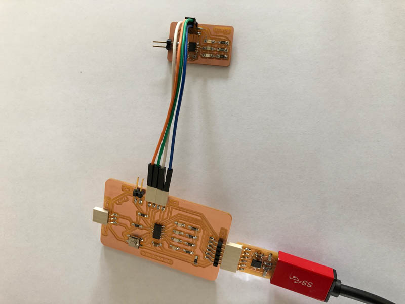
A final task remains: creating a network for the two ATtiny boards. This is how the small Student board is connected to the Teacher.
Next, program the ATtiny. I started with two example files from the Wire library. As you might have noticed, I replaced the objectionable ‘master-slave’ terminology for ‘teacher-student’ in this documentation.
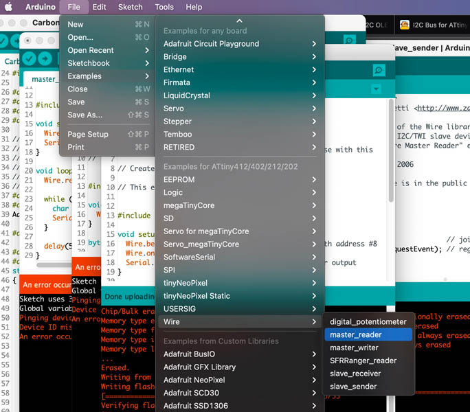
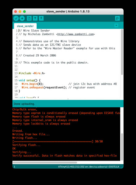
Code for the node sender:
// Wire Student Sender
// by Nicholas Zambetti <http://www.zambetti.com>

// Demonstrates use of the Wire library
// Sends data as an I2C/TWI Student device
// Refer to the "Wire Master Reader" example for use with this

// Created 29 March 2006

// This example code is in the public domain.


#include <Wire.h>

void setup() {
  Wire.begin(8);                // join i2c bus with address #8
  Wire.onRequest(requestEvent); // register event
}

void loop() {
  delay(100);
}

// function that executes whenever data is requested by master
// this function is registered as an event, see setup()
void requestEvent() {
  Wire.write("hello "); // respond with message of 6 bytes
  // as expected by master
}
The interesting thing about this example is that address 8 works, in contrary to 0x30 as listed in the data sheet. This makes the list complete:
Node 1: CO2 0x61
Node 2: OLED 03xC
Node 3: ATtiny412 with LEDs 0x08 or 8
This successfully uploaded to the device.
Code for the teacher reader:
// Include the required Wire library for I2C<

#include <Wire.h>
int LED = 1;
int x = 0;

void setup() {
  // Define the LED pin as Output
  // Start the I2C Bus as Student on address 9
  Wire.begin(0x08);
  // Attach a function to trigger when something is received.
  Wire.onReceive(receiveEvent);

 // Serial.swap(1);
  Serial.begin(9600);

  pinMode (LED, OUTPUT);

}
void receiveEvent(int bytes) {
  while(Wire.available()) {	// read all bytes received
		x = Wire.read();
    Serial.print(x);
	}
}

void loop() {

  digitalWrite(LED, HIGH);

  //If value received is 0 blink LED for 200 ms
  if (x == 0) {
    digitalWrite(LED, LOW);
    delay(500);
  }
}
Working code + resistors
With the help of Nadieh it succeeded to create a solid I2C connection between the two boards. Because there is no Tx Rx on the node, we switched it around with Serial.swap(1).
Student program sender:
// Wire Master Writer
// by Nicholas Zambetti <http://www.zambetti.com>

// Demonstrates use of the Wire library
// Writes data to an I2C/TWI student device
// Refer to the "Wire Student Receiver" example for use with this

// Created 29 March 2006

// This example code is in the public domain.


#include <Wire.h>

// Include the required Wire library for I2C<br>#include
int x = 0;
void setup() {
  // Start the I2C Bus as Master
  Wire.begin();
}
void loop() {
  Wire.beginTransmission(0x08); // transmit to device #9
  Wire.write(x);              // sends x
  Wire.endTransmission();    // stop transmitting
  x++; // Increment x
  if (x > 5) x = 0; // `reset x once it gets 6
  delay(500);
}
Teacher receiver:
// Include the required Wire library for I2C<

#include <Wire.h>
int LED = 1;
int x = 0;

void setup() {
  // Define the LED pin as Output
  // Start the I2C Bus as Student on address 9
  Wire.begin(0x08);
  // Attach a function to trigger when something is received.
  Wire.onReceive(receiveEvent);

 // Serial.swap(1);
  Serial.begin(9600);

  pinMode (LED, OUTPUT);

}
void receiveEvent(int bytes) {
  while(Wire.available()) {	// read all bytes received
		x = Wire.read();
    Serial.print(x);
	}
}

void loop() {

  digitalWrite(LED, HIGH);

  //If value received is 0 blink LED for 200 ms
  if (x == 0) {
    digitalWrite(LED, LOW);
    delay(500);
  }
}
Video of very softly blinking LED: signal not strong enough. It’s a very weak signal. But it’s there!
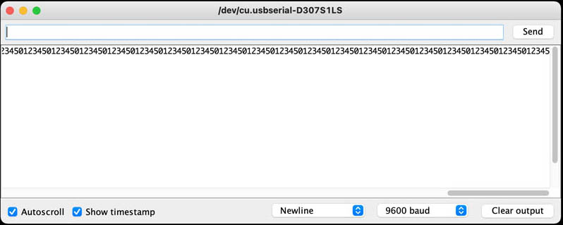
I asked Nadieh for help and she recommended to open the Serial Monitor and see what’s going on. This is what arrived:
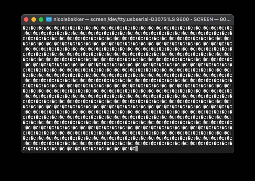
Not exactly what we want! After a while I realized that because I recycled my board from Output Devices it didn’t have the two pull-up resistors in between VCC-SCL and VCC-SDA, as can be seen in Neil’s example.
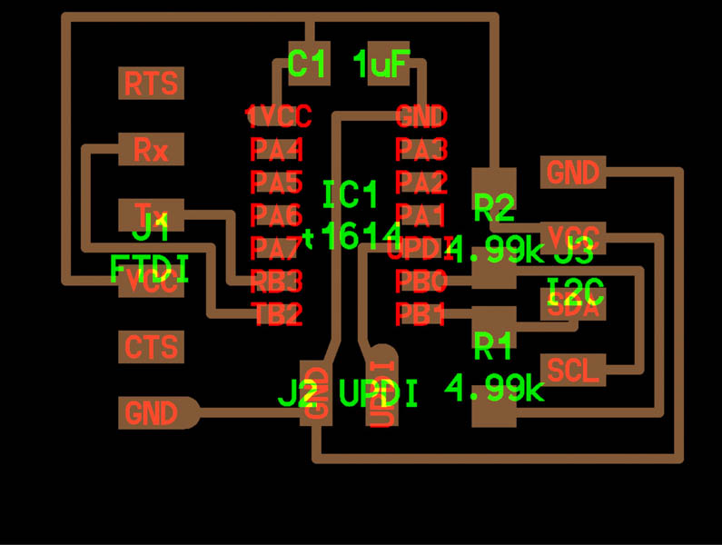
Here is a simplified schematic of adding the two 4.99k resistors.
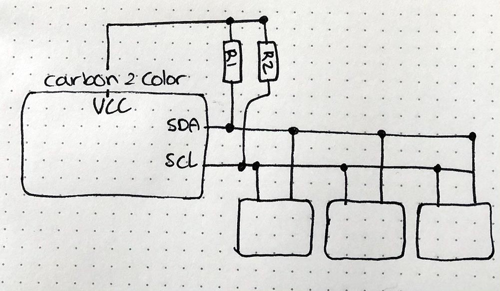
This helped! Here is a video of correctly blinking LED.
Checking the Serial Monitor, and yes!
Now let’s do this the other way around: master sends code to node.
// Wire Master Writer
// by Nicholas Zambetti <http://www.zambetti.com>

// Demonstrates use of the Wire library
// Writes data to an I2C/TWI Student device
// Refer to the "Wire Student Receiver" example for use with this

// Created 29 March 2006

// This example code is in the public domain.


#include <Wire.h>

// Include the required Wire library for I2C<br>#include
int x = 0;
void setup() {
  // Start the I2C Bus as Master
  Wire.begin();
}
void loop() {
  Wire.beginTransmission(0x08); // transmit to device #9
  Wire.write(x);              // sends x
  Wire.endTransmission();    // stop transmitting
  x++; // Increment x
  if (x > 5) x = 0; // `reset x once it gets 6
  delay(500);
}
And the code for the receiving node:
// Include the required Wire library for I2C<

#include <Wire.h>
int LED = 1;
int x = 0;

void setup() {
  // Define the LED pin as Output
  // Start the I2C Bus as Student on address 0x08
  Wire.begin(0x08);
  // Attach a function to trigger when something is received.
  Wire.onReceive(receiveEvent);

 // Serial.swap(1);
  Serial.begin(9600);

  pinMode (LED, OUTPUT);

}
void receiveEvent(int bytes) {
  while(Wire.available()) {	// read all bytes received
		x = Wire.read();
    Serial.print(x);
	}
}

void loop() {

  digitalWrite(LED, HIGH);

  //If value received is 0 blink LED for 200 ms
  if (x == 0) {
    digitalWrite(LED, LOW);
    delay(500);
  }
}
Video of working program on node. The LED is indeed blinking. However, the red LED is blinking where it’s supposed to not do that.
As can be seen below, the regular LED program works, so it’s not a hardware issue with the LED:
This is the code.
int LED1 = A6;
int LED2 = A7;
int LED3 = A3;


void setup() {
pinMode (LED1, OUTPUT);
pinMode(LED2,OUTPUT);
pinMode(LED3,OUTPUT);
}

void loop() {

// LED1 = red
{
   digitalWrite(LED1,HIGH);
   delay(100);
   digitalWrite(LED1,LOW);
   delay(100);
   }


// LED2 = orange
{
   digitalWrite(LED2,HIGH);
   delay(100);
   digitalWrite(LED2,LOW);
   delay(100);
   }


// LED3 = green
{
   digitalWrite(LED3,HIGH);
   delay(500);
   digitalWrite(LED3,LOW);
   delay(500);
   }

}
Adding in the sensor.
Reflections
For someone with very limited programming experience, networking is hard! I was quite proud that I made the OLED work with two alternative libraries, thereby reducing the need for a new board and larger ATtiny - aka more material use.
Downloads
Explore more like this
Week 17 Invention, Intellectual Property and Business Models
After acing through the technical assignments of Fab Academy, the last two weeks have a lighter load so we can focus on the final project. But this does not mean...
Week 16 Applications and Implications
Propose a final project masterpiece that integrates the range of units covered, answering: