Group assignment:
- Test runout, alignment, speeds, feeds, and toolpaths for your machine
- Document your work (in a group or individually)
Individual project
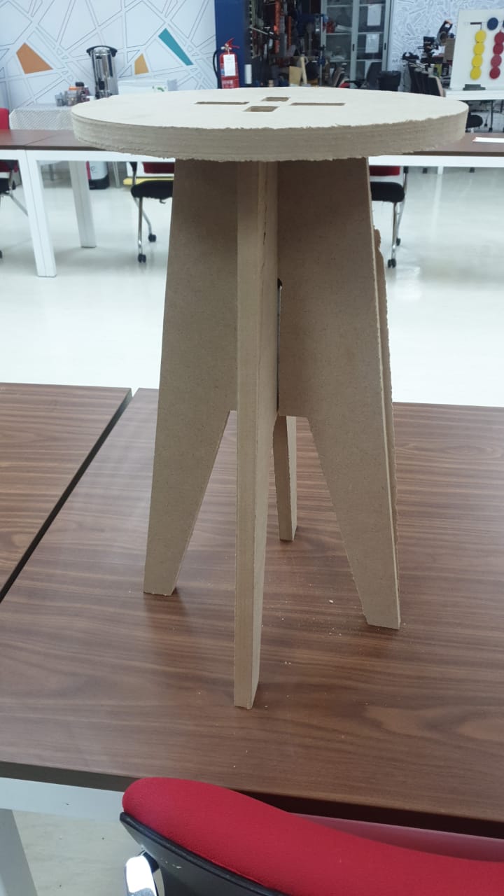
- Make (design+mill+assemble) something big
programs that i will test
for this week we have been asked to test and evaluate more than one design software, so i was searching on the internet focusing first the program that i will use should be offer free use or to be open-source, because in the lab most of my student are still studying at school and they may not have the budget to pay for a fancy software license, so i found these tow
-
Onshape it offer a free student license, and it can run on the cloud so this will be good choice for my student to work with
-
freecad is an open source software that make it good fit also , and actually what make this software my favorite that its light and can work on raspberry pi so am planning to use it with the pi more after the academy
Design with Freecad
.
.
Download FreeCAD from Here
First you need to choose which CAD software You are Going to use i have made full documentation on CAD Software’s You will find it here
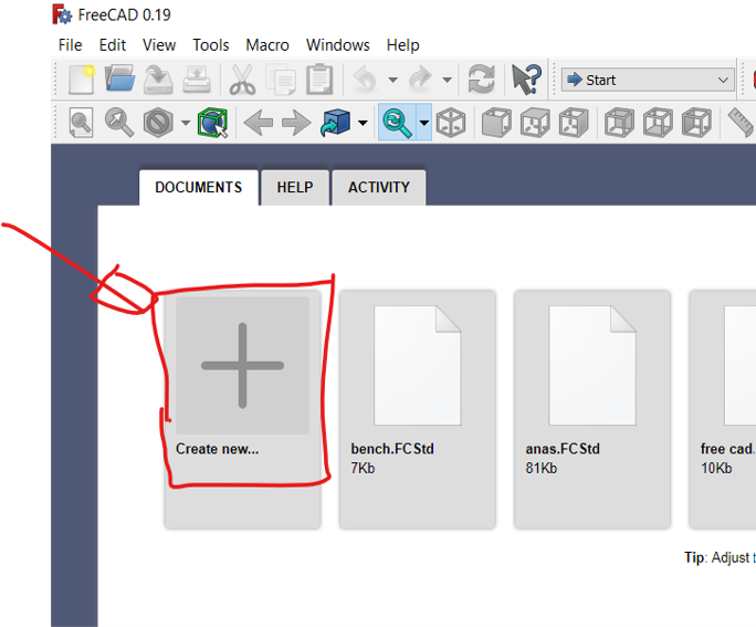
Getting Started
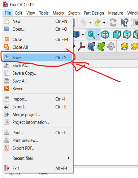
Start by creating a project, then save it in any folder in your local computer
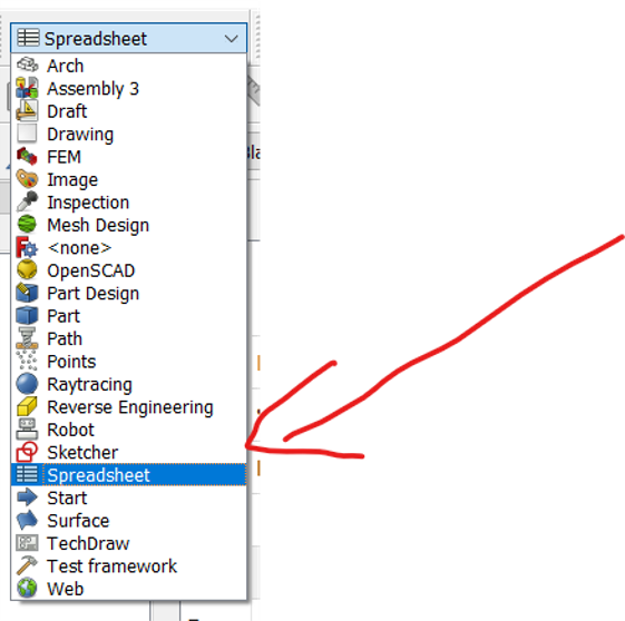
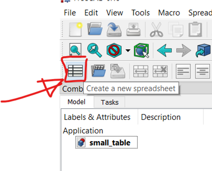
Create spreadsheet
from the Workbench menu choose spreadsheet, then create a new spread sheet , we will use the spreadsheet to create variable to make it easy for us to re use it as constrain in the design
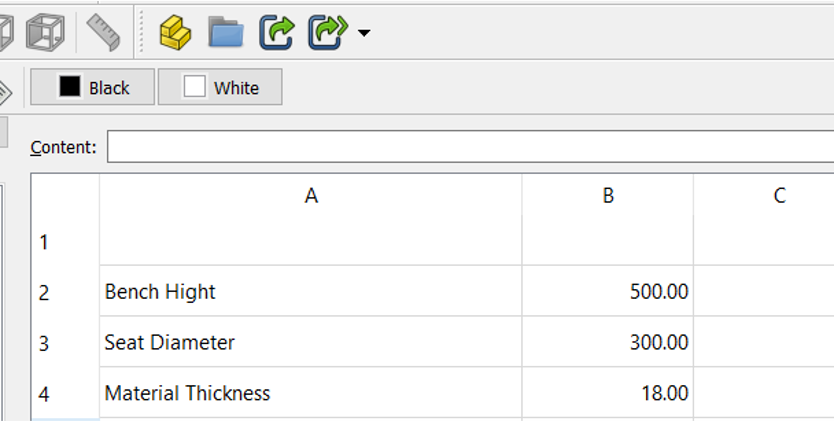
Create Variables
Now we are going to specify variable that we will use it in the design later, we are using variable to make it easy to modify later on in the design Name your variable and specify its value, we are going to use mm as drawing reference
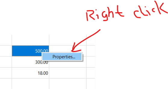
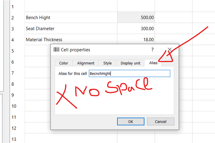
Alias Variable
Now right click on the value, and open properties From the top bar menu click Alias , and make allice for the sell you cant use spaces here so it either by capital letter ex ( BenchHight ) or ( bench_hight ) or ( benchhight ) use the one you are most comfortable with
Then save the spread sheet in your project folder
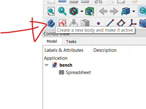
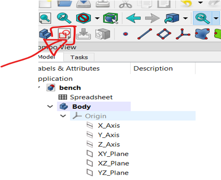
Create body
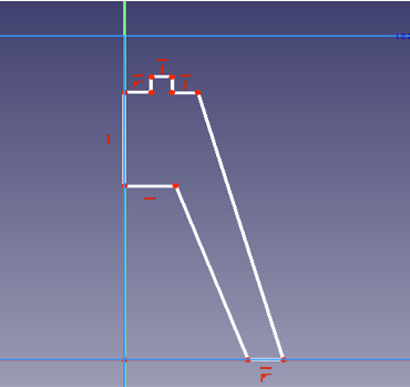
the first step in designing parts in FreeCad is to create a body, then create new sketch and choose the plane you want to draw on, we will use the ZX plane because we will start by drawing the base and we want to see it from front in order to extrude it later.
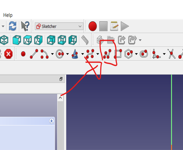
Sketch the shape first
now lets draw the base of the Table how we want it to be
Sketch the shape first
Now lets draw the base of the Table how we want it to be
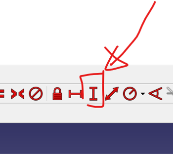
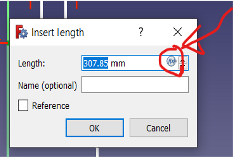
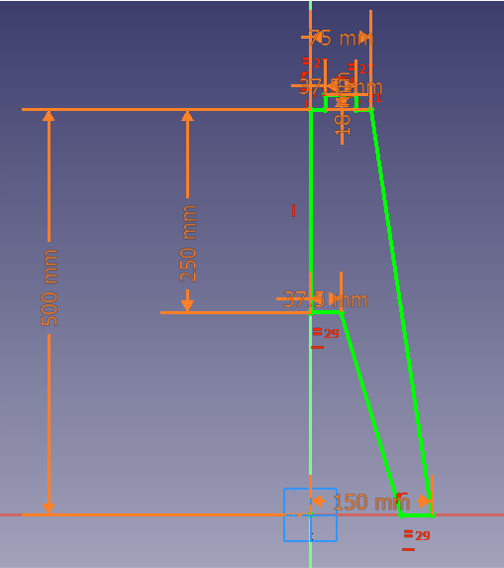
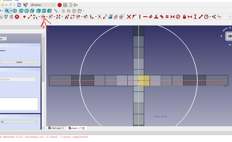
Adding Constrain
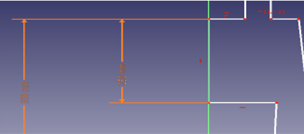
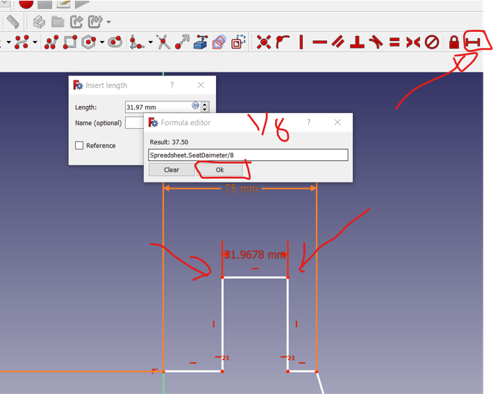
Next we used the dimension constrain, and then a window will show up asking for the exact value, click the blue icon next to the number , then type spreadsheet. Then a list will show up choose the variable that you specified earlier
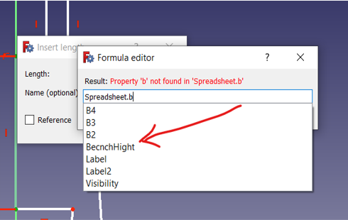

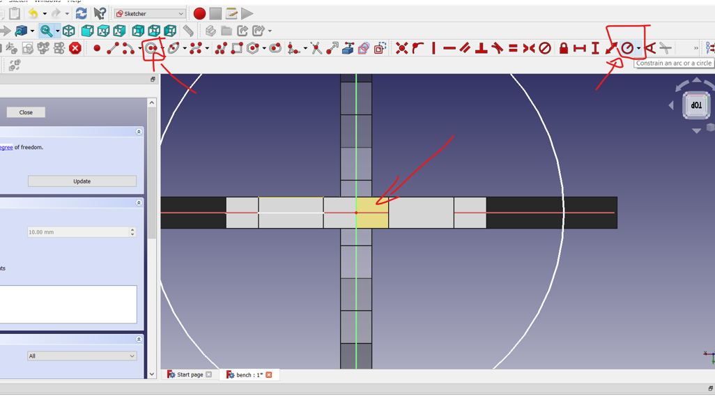
Next we add another constrain for the Hight of the center of the base, we did the same steps but now we divided the Hight by 2 to take the half of the dimension
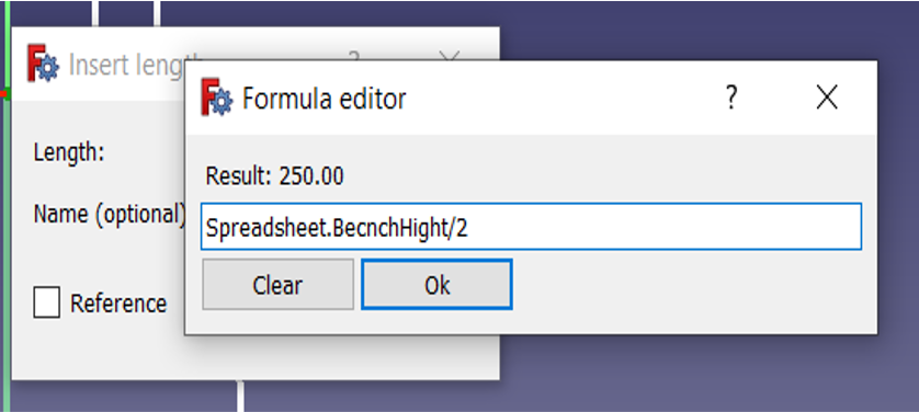
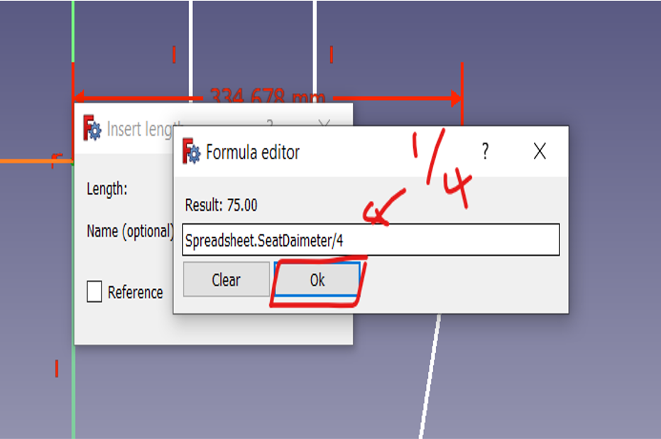
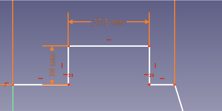
Now lets make another dimension constrain, this time is for the top of the base It should be ¼ of the full dimeter because we are already drawing the half of it and then half of the half
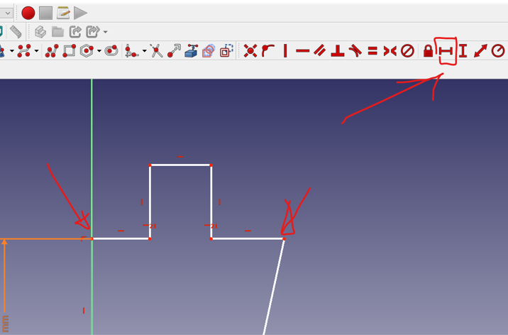
Now for the joint lets make it 1/8 of the full dimeter
And the height of it will be the material thickness
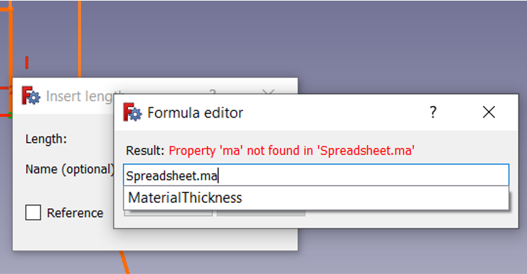
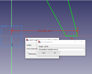
as i wanted every Dimension to be constrained i made the legs also to be related to the dimeter by dividing it by 2
and here is the first part of the sketch is done
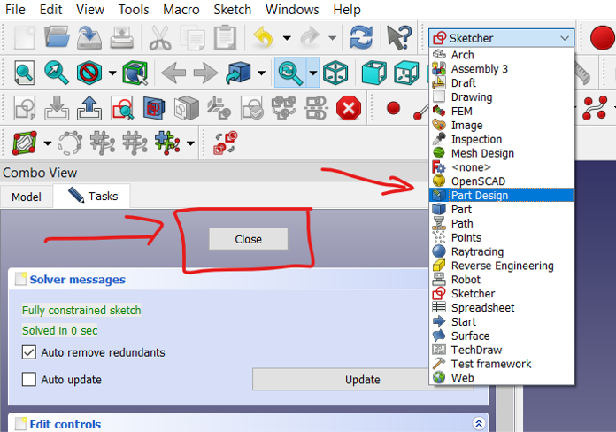
Next is to close the sketcher and go back to part design to continue other steps
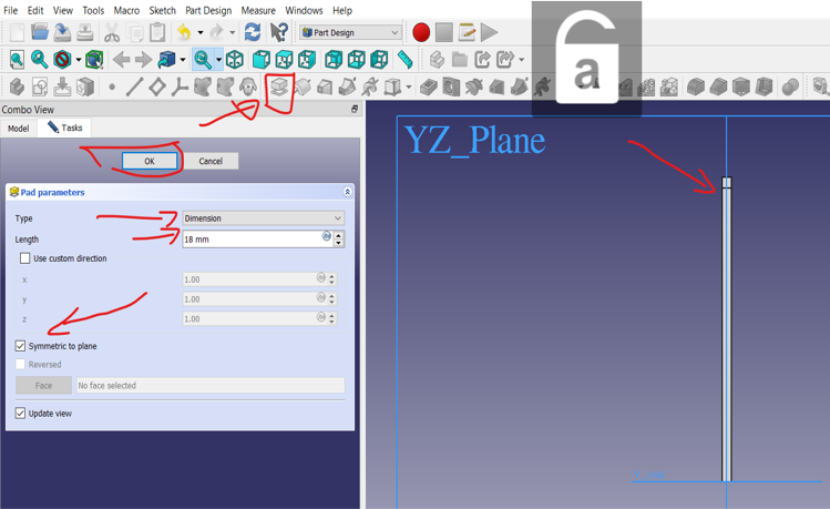
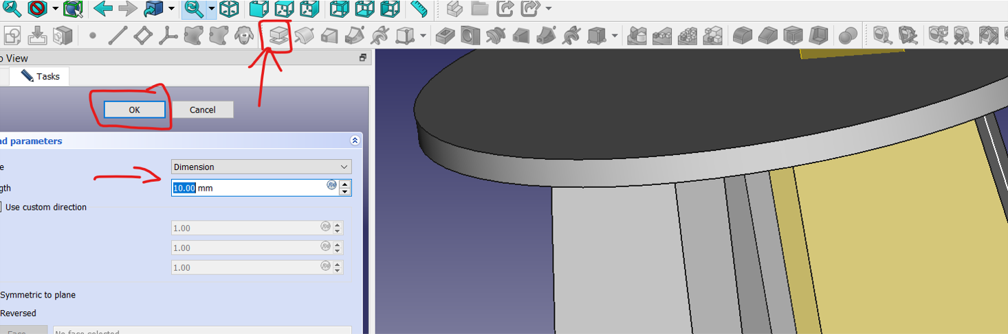
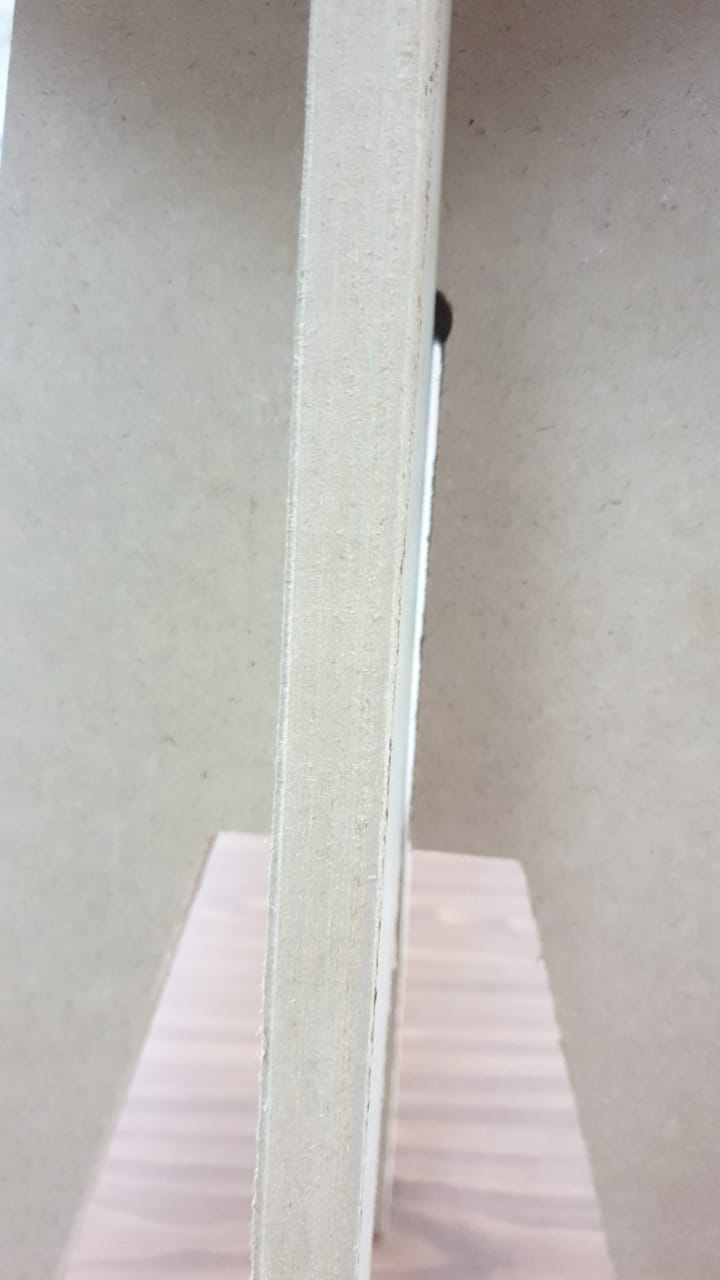
Next is to extrude the design and make sure to use the correct dimension of the sheet, We are using MDF and the thickness is 18 mmm and we will make it symmetric
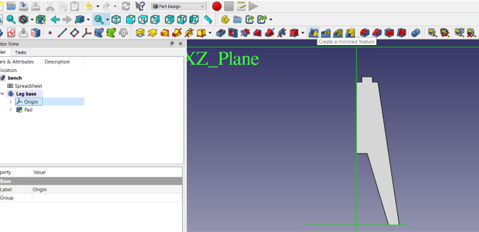
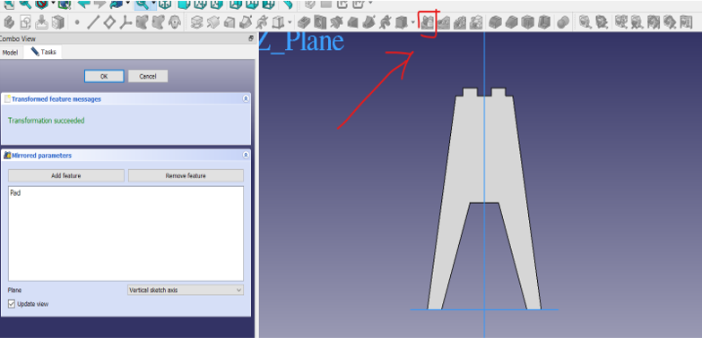
Now lets mirror the object and by click the mirrir button it will mirror the active object to the othe r side and we can notice here that its automaticly choose the yz plane
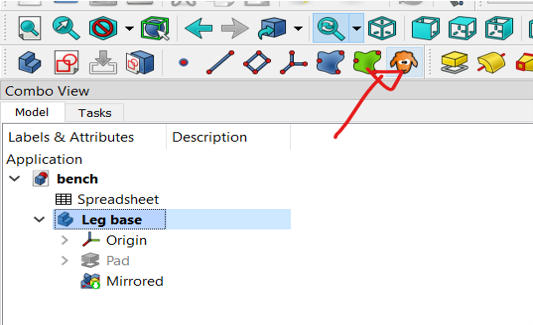
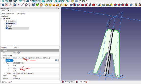
next clone the object in order to have it similar Then rotate it around the z axis 90 degree
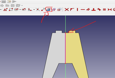
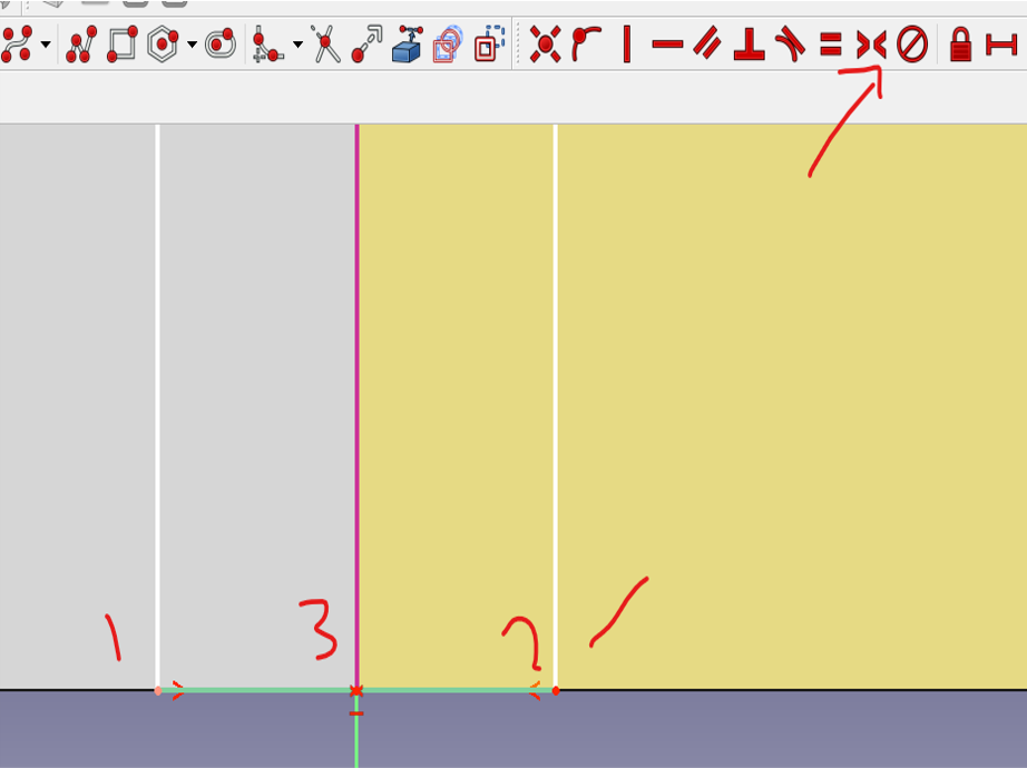
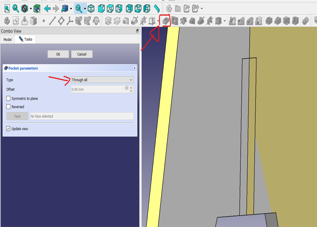
now we need to make a hall for the tow side to be fit together
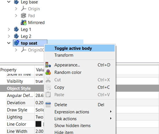
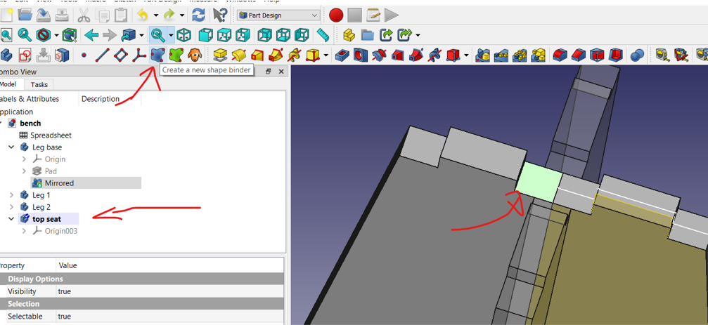
Now lets make the top part of the table, you need first to toggle the body to make it active, then create a new shape binder on the top of the table as showing below
Create a new sketch and make the shape binder you created as your plane , and draw the top shape you want on top of legs, and make sure to use constrain that connect it with the sheet we made before, use the dimeter constrain
then extrude it using pad tool with the same as material thickness
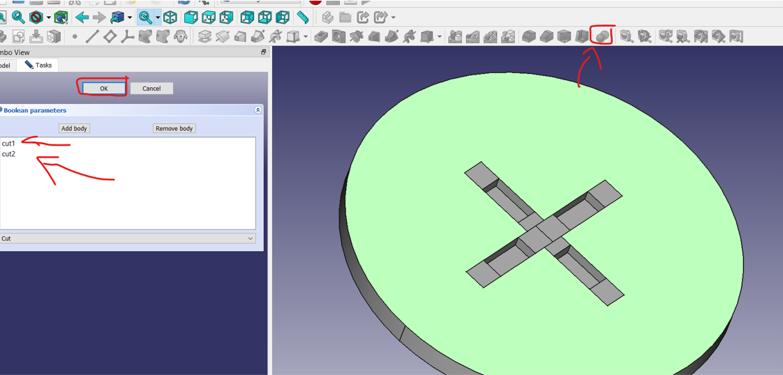
and use the boolean operation to cut through the top part of the table
last step is to export the file to svg or pdf depending of the other software you will use to generate a toolpath
prepare the Design and generate the toolpath
for doing this job i will be using VCarve pro

before importing the file make sure to convert it to its actual size
when i exported the file from FreeCad i made the reference size 1:10 then i used inkscape to converting it to its actual size

Start new project
start by creating a new project and open it to a location in your local device
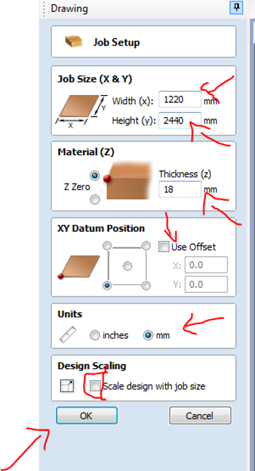
set the sheet dimension
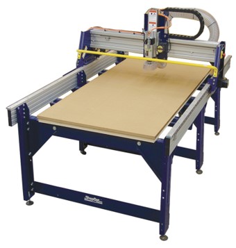
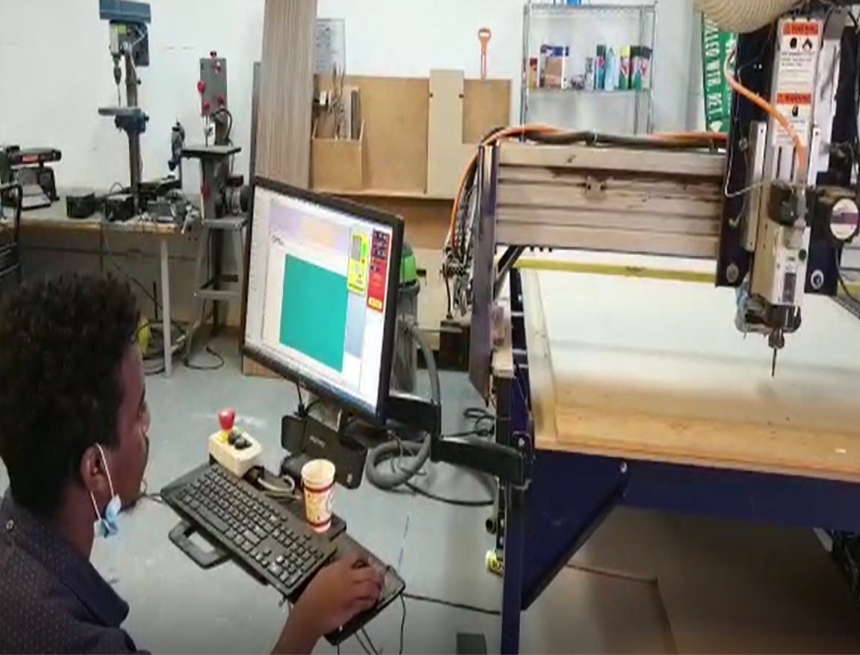
i am using Shopbot alpha 96*48 so its important to know first you machine dimension
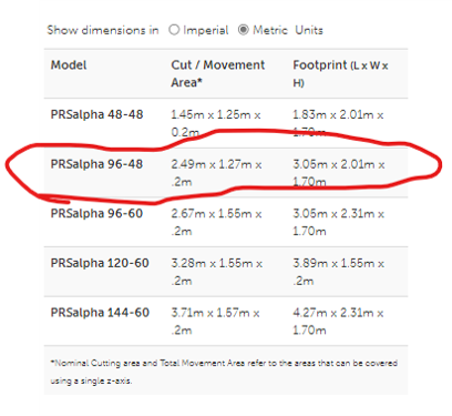
- once you know your machine dimension set the sheet dimension on v carve
- and set the thickness of the sheet
- use Offset to make the machine start on its origin and choose which corner you are referring to
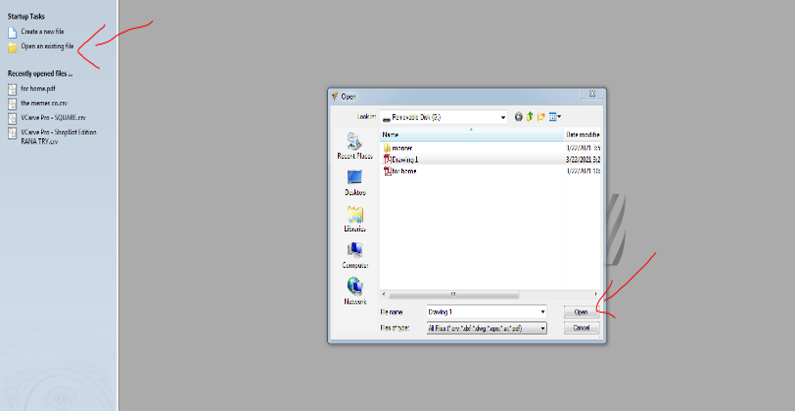
import the design
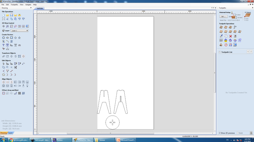
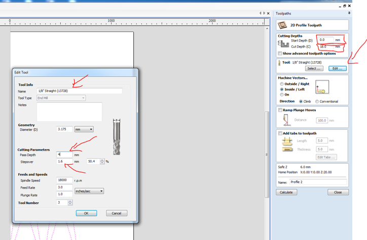
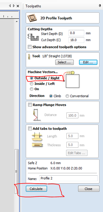
type of cut
- profile : this will cut the vectors depending on the cutdepth you will choose
- poket : this is used for engraving
- drilling : is used to fix the object
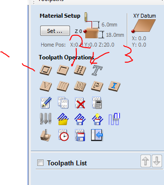
- i will choose profile as iam just cutting my design now
- next make sure thet the tool setting is the same as the bit on the machine
- if not you can select the same as the one in the machine
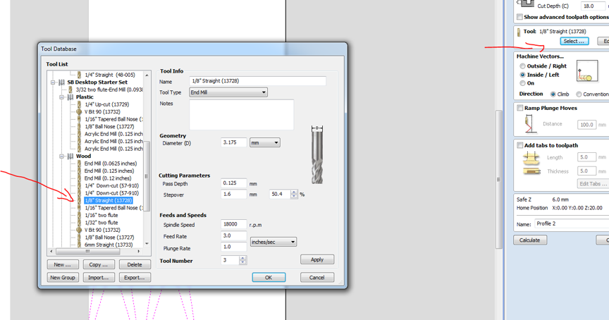
- then cheese the start cut and the max Depth you want to cut
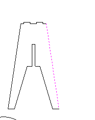
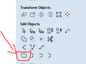
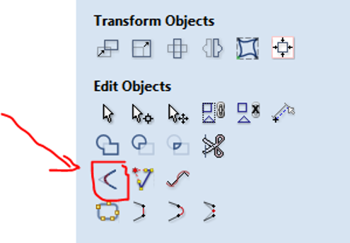
join the vectors
when i wanted to use the dog bone in my design an error accured that the vector is not connected so i used the join function to make them close as one body
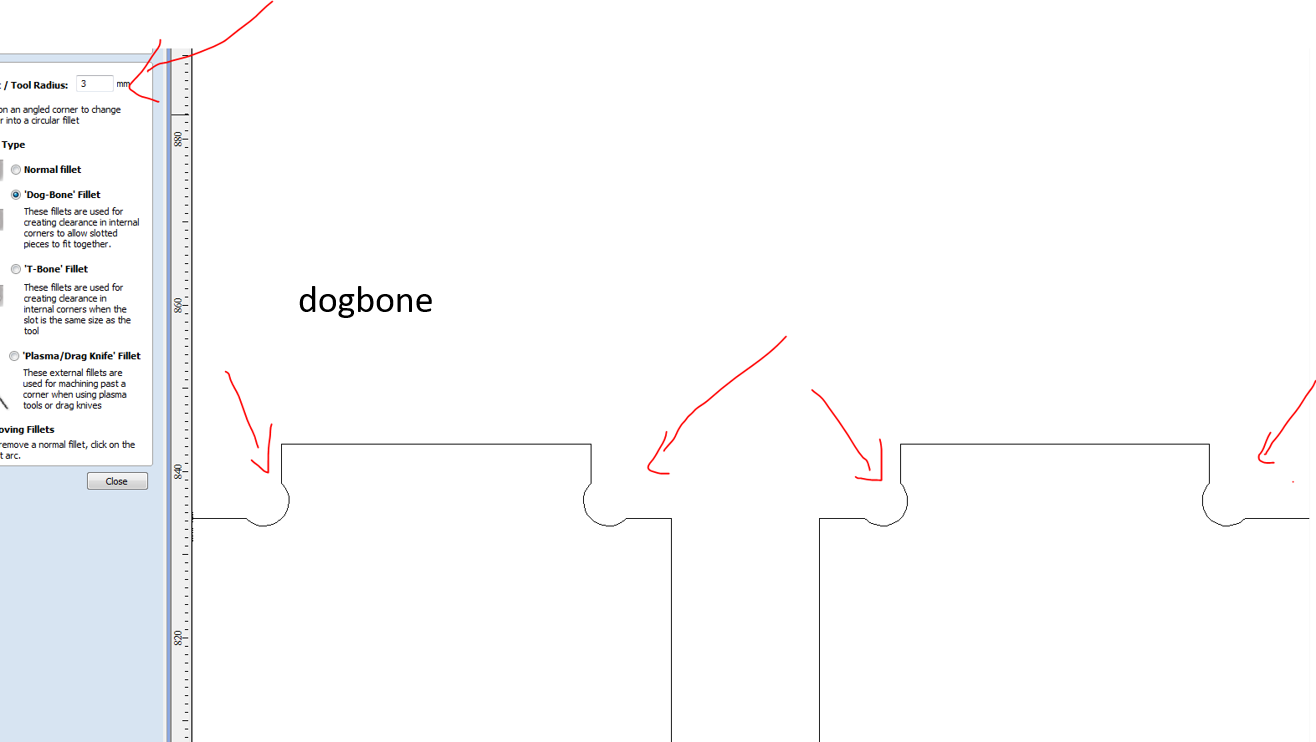
Dog bone
Dog bone corners are a jargon-y way to describe the shape of a corner that is extended outside the cut area to create a perfect 90º corner that looks like the cartoon shape of a canine chew toy
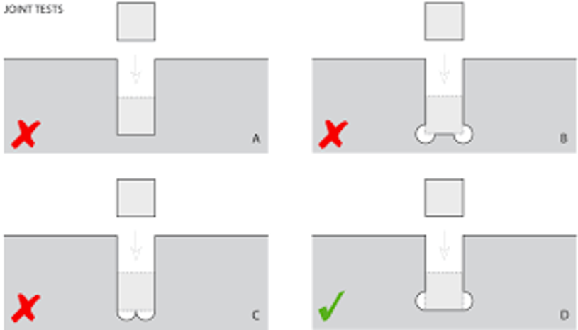 image from here
If you want to make joints you have to be carefull of the cnc kerf and design with T-bones or DogBones
Vcarve has this function ready in the software
i applied it to each corner of the joint
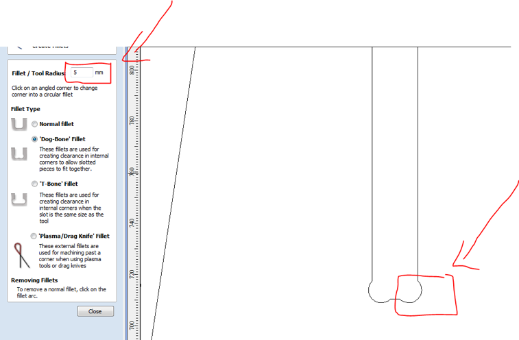
then choose you want the cut to be from inside the vector or from out side, them click calculate
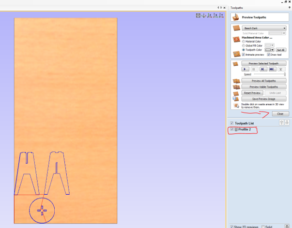
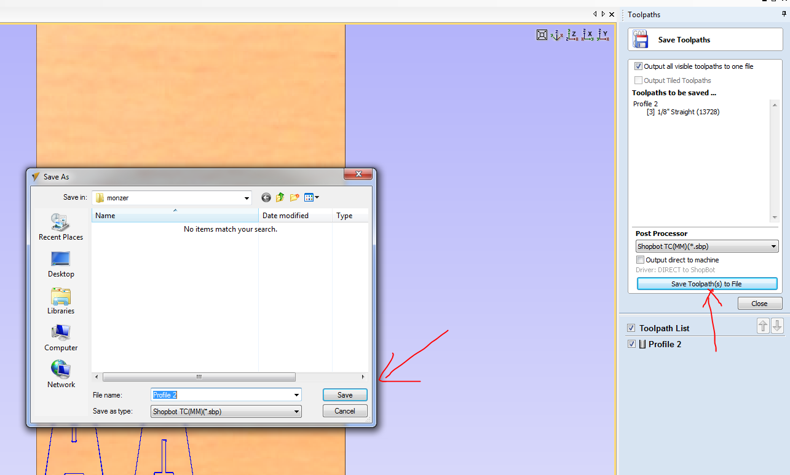
save the tool path and go to machine now we are done here
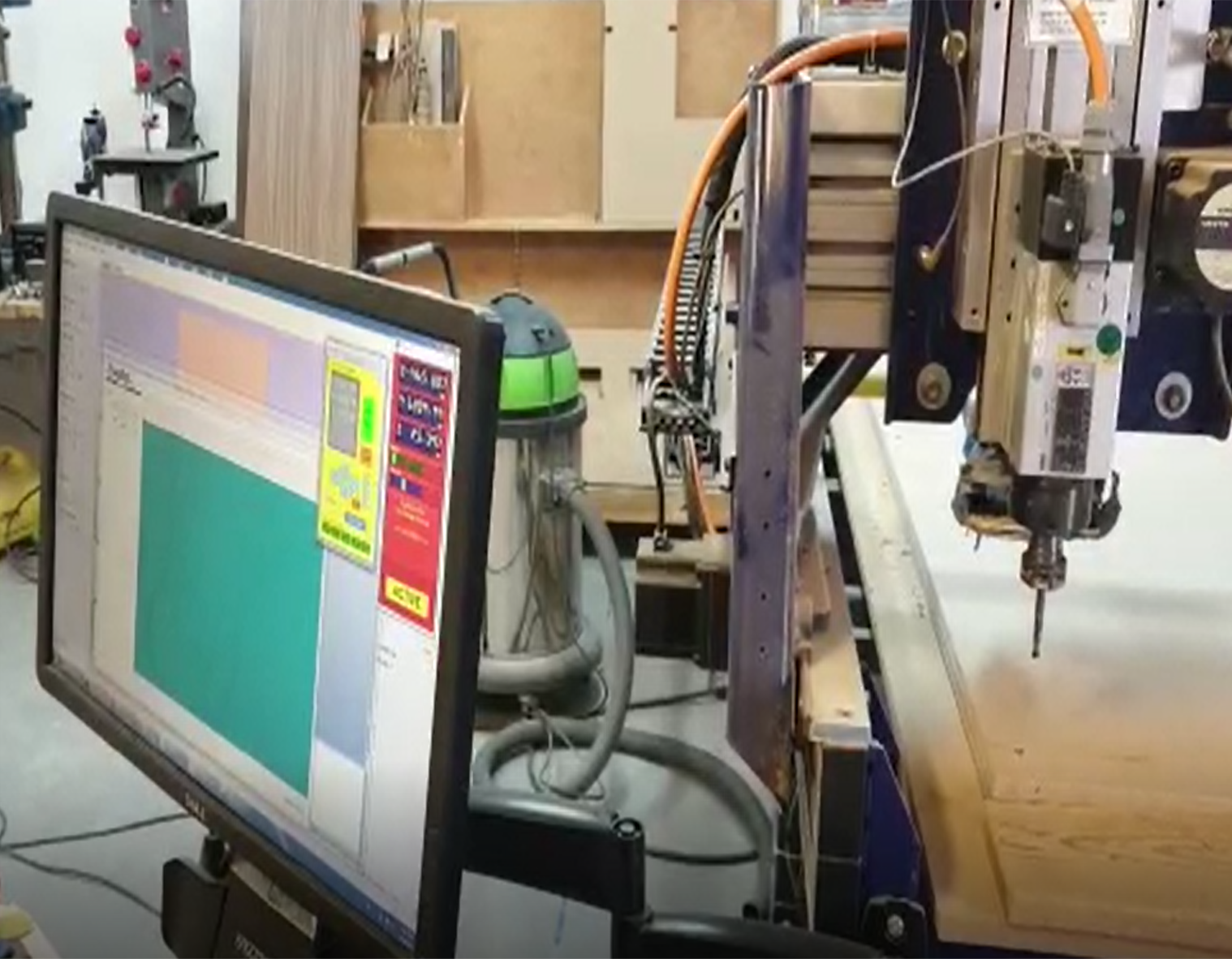
Shopbot
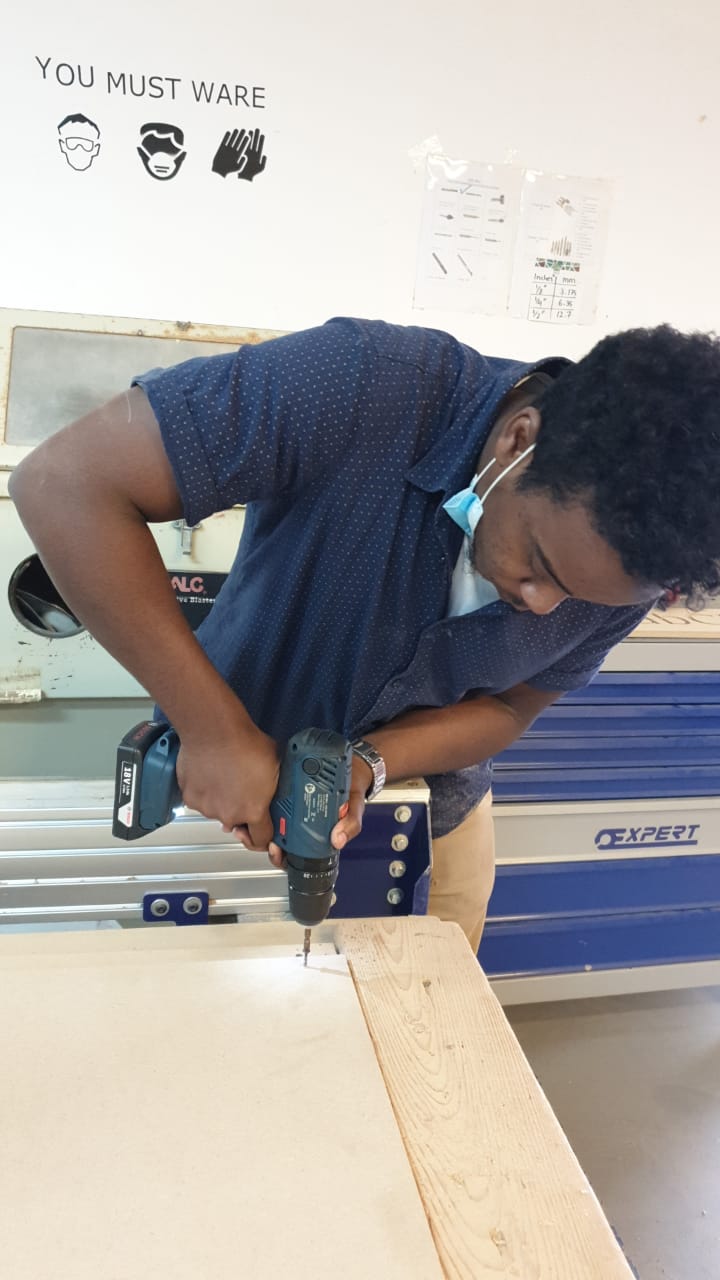
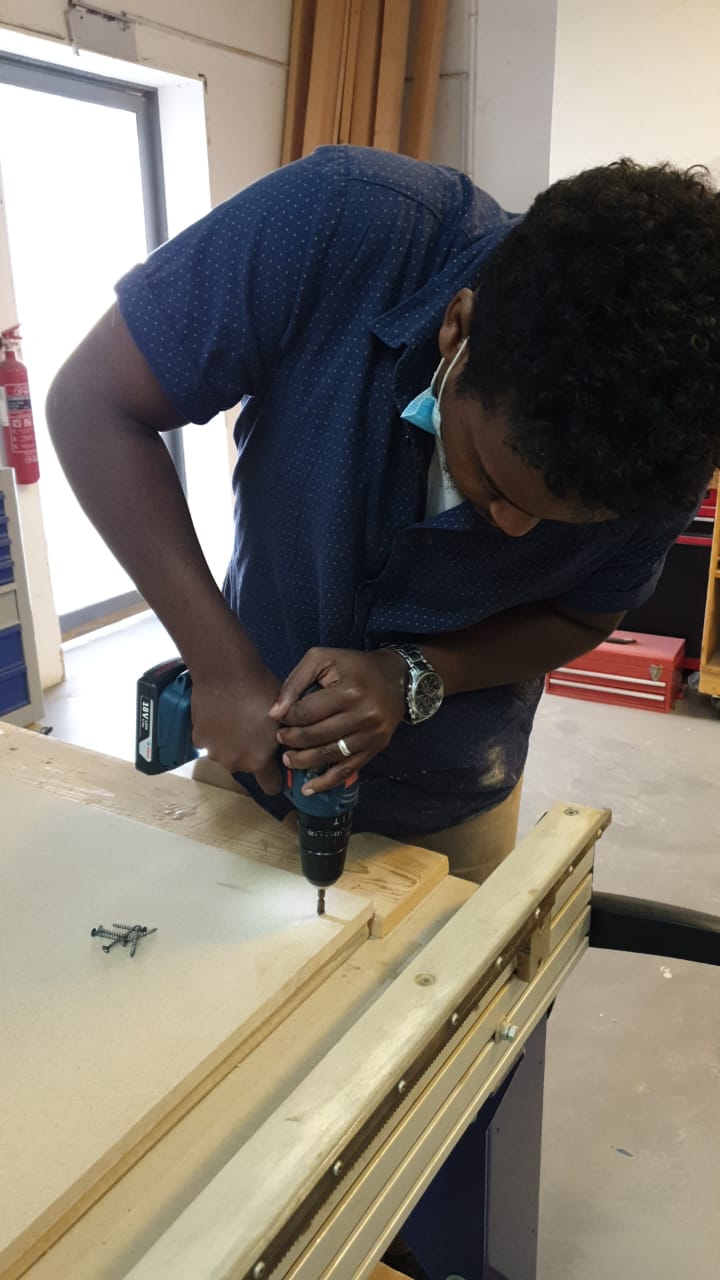
- fix the MDF sheet on the machine with wood scrow to make it stable during the cut
Set the Origin for X and Y
- now open shopbot 3 software
- move the bet across the x and y axis till it reach to the place you want it to be your origin
- then make it zero for X and Y
Set the Origin for z
for z axis it has another instruction and step you have to follow
- first place the metal plate on top of your sheet and underneath the dril bit
- connect the metal plate to a scrow that is touching the body of the machine for grounding , there is one on the motor of z axis
- then click ok for the machine to start doing the process automatically
Now you are good to go click START and let the magic happen
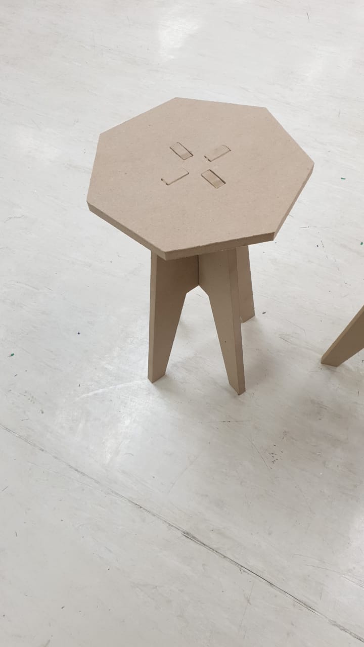
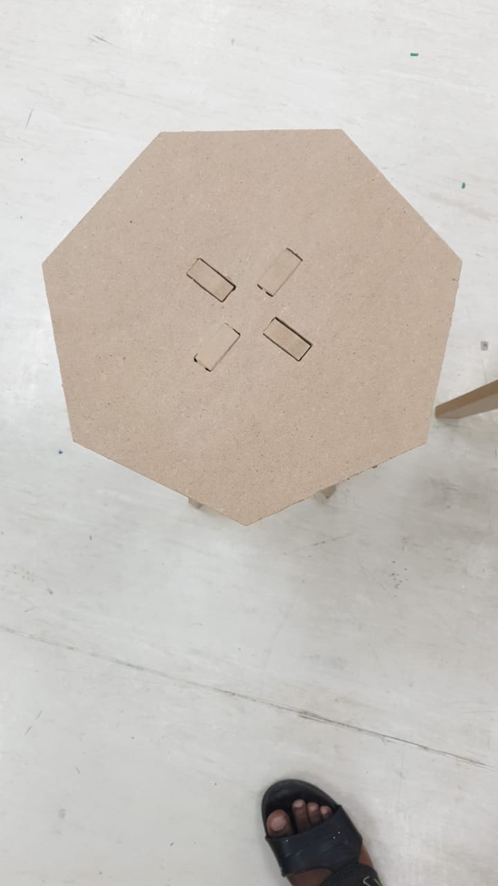
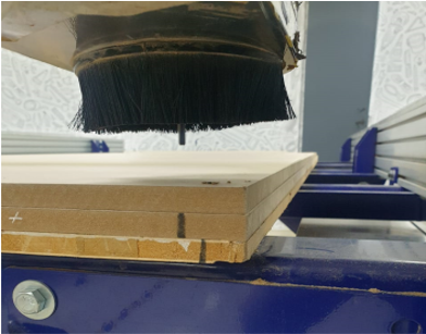
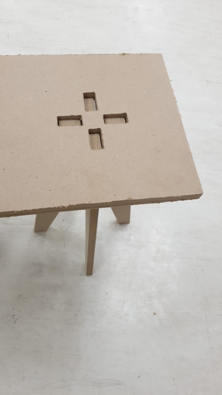
the Result
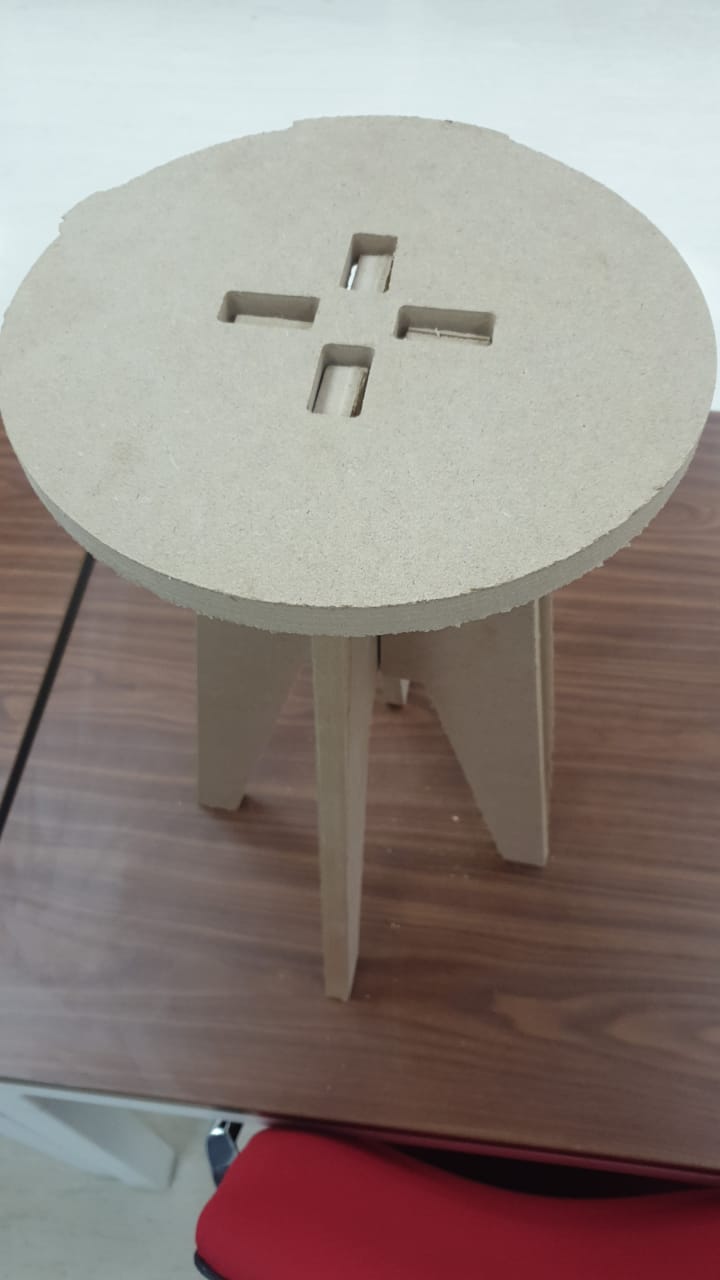
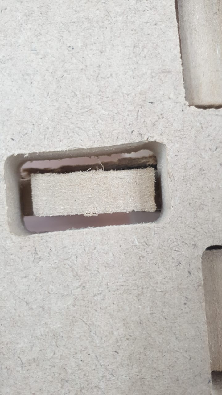
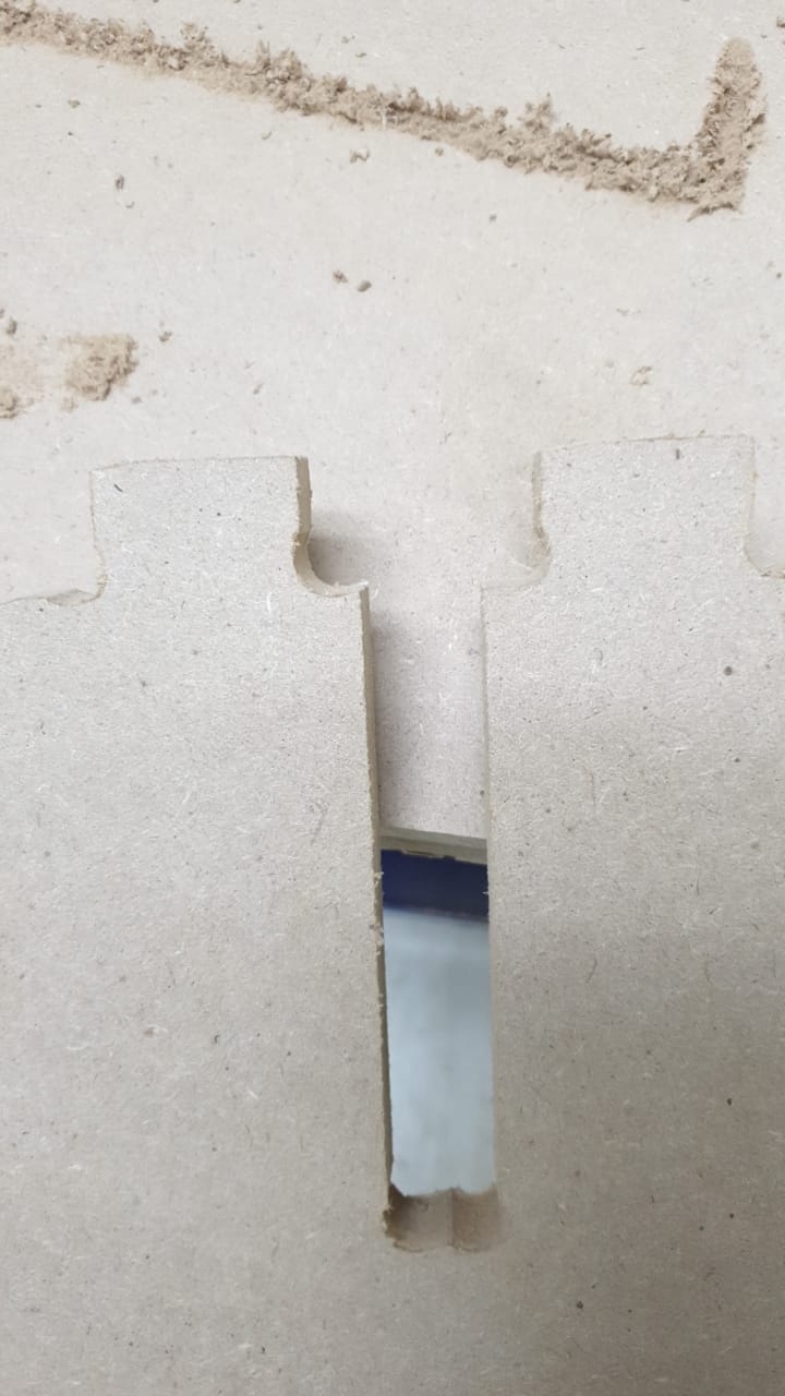
problems
there is a gap between the joints i will fix it in the next cut
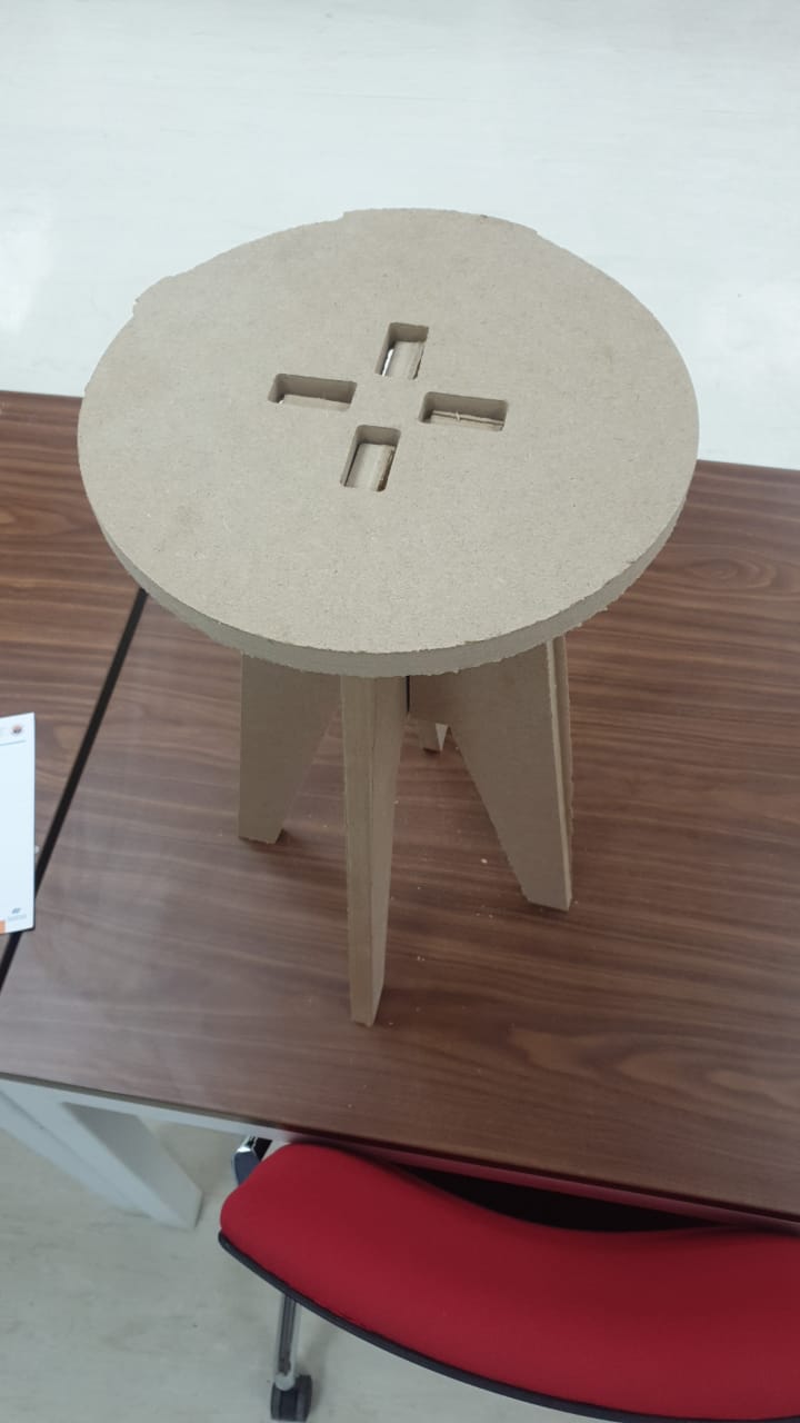
Second cut
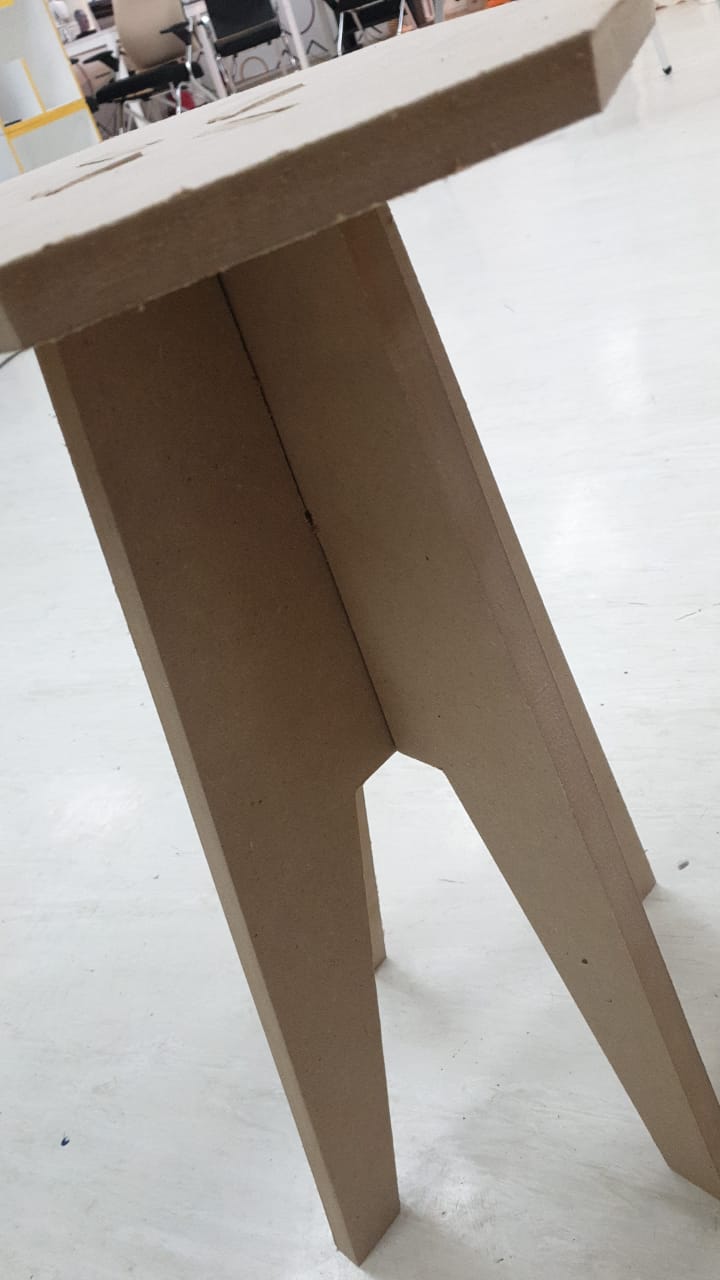
problems
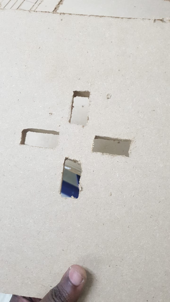
still there is a gap between the joints i will change the dimension according to joint fit setting we did in the group assignment
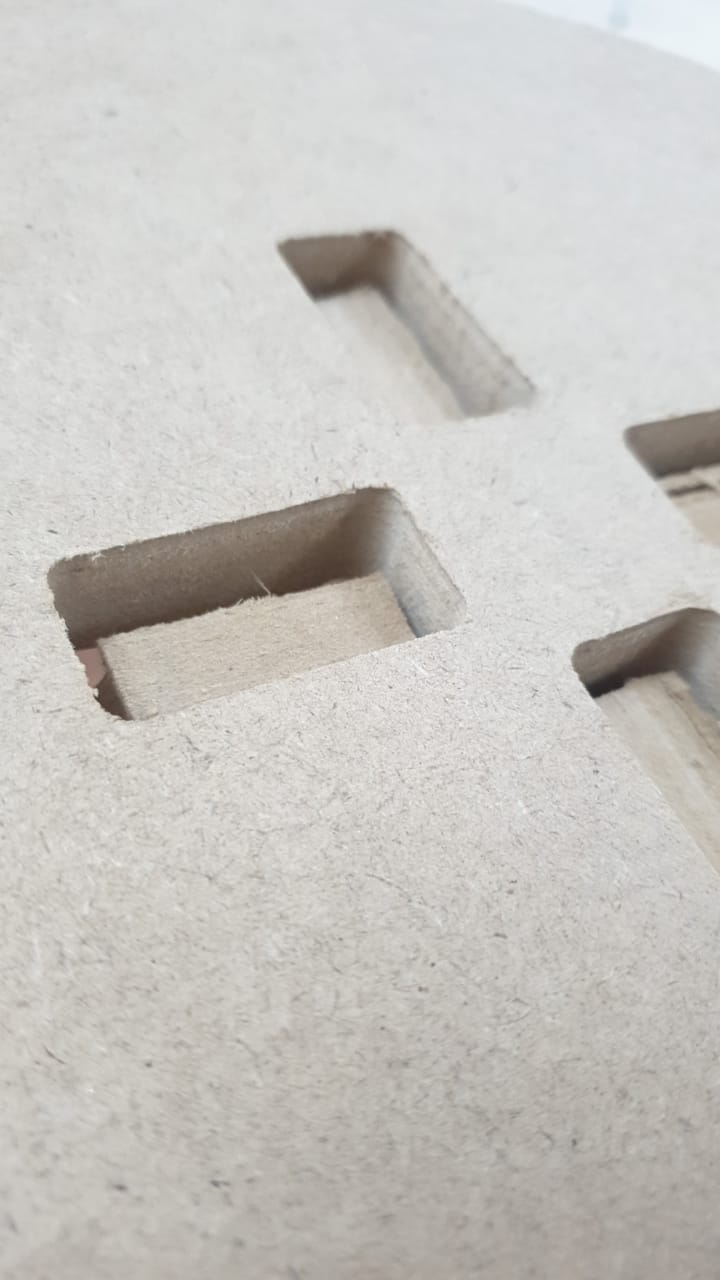
Solved
the problem was the size of the dogbone i just increased it to be 4
Third and Final cut