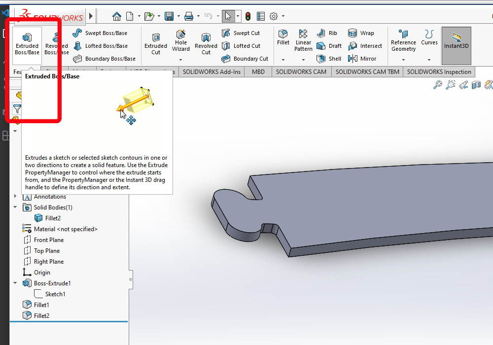
Starting design in Solid Works
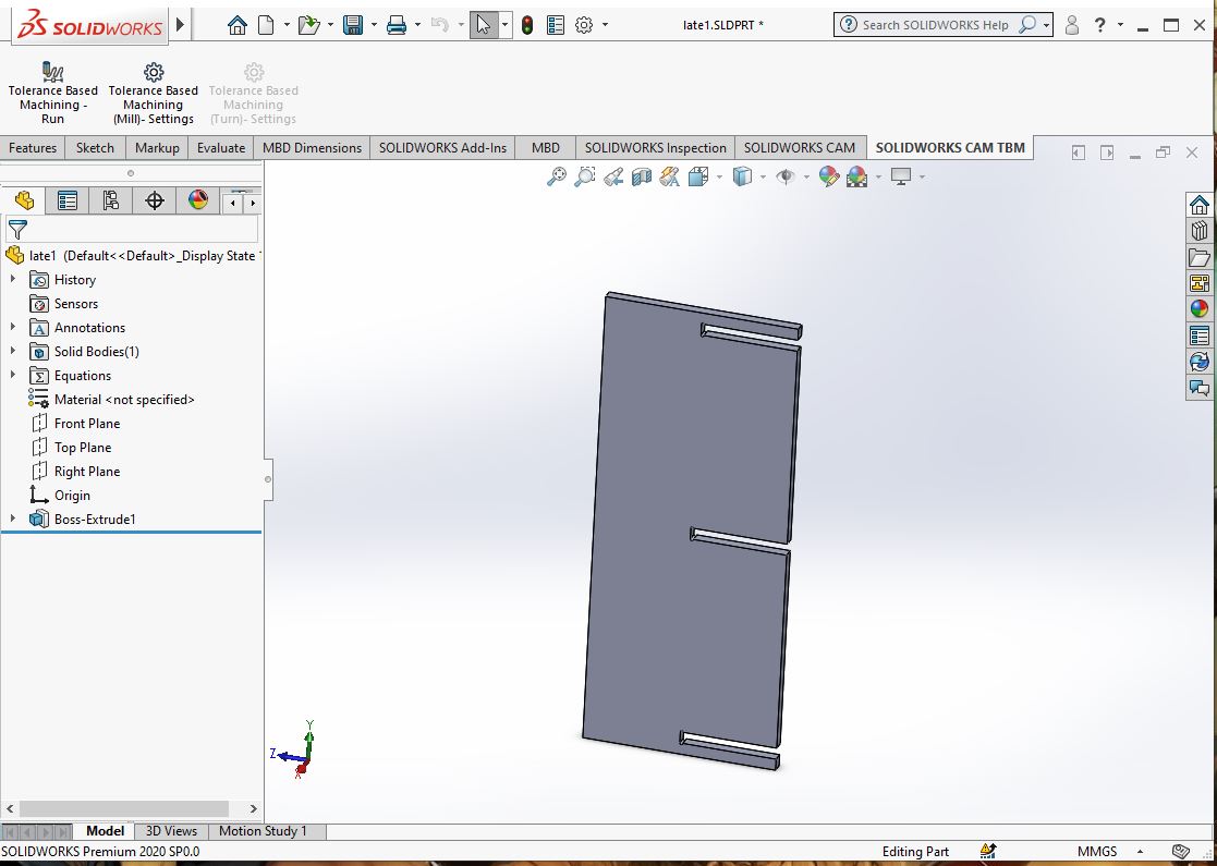
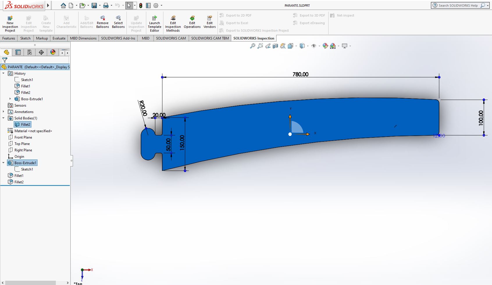
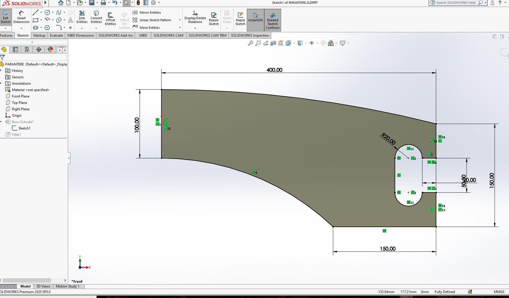
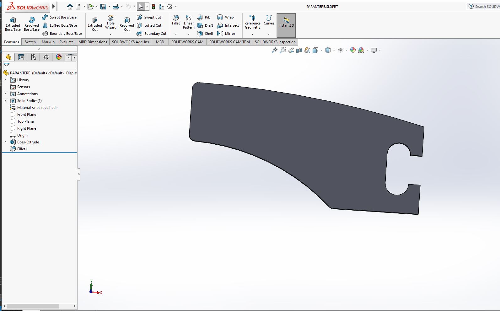
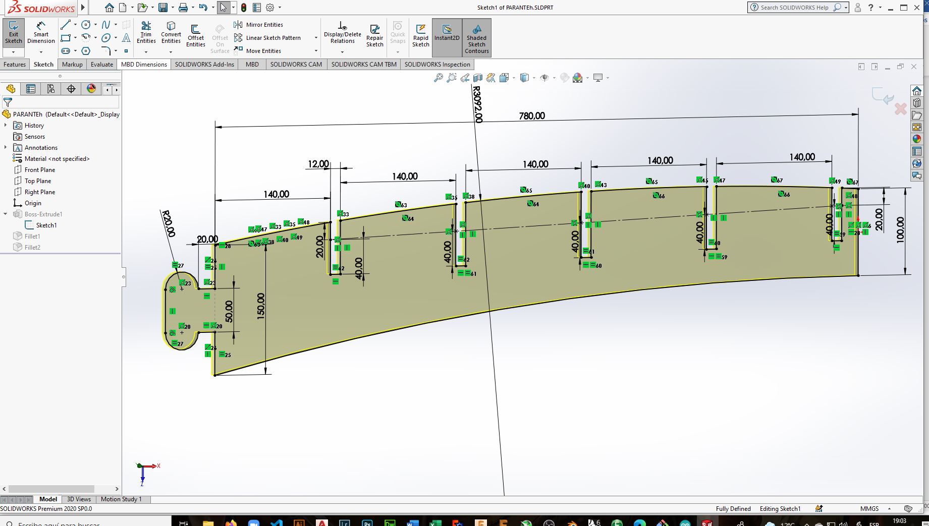
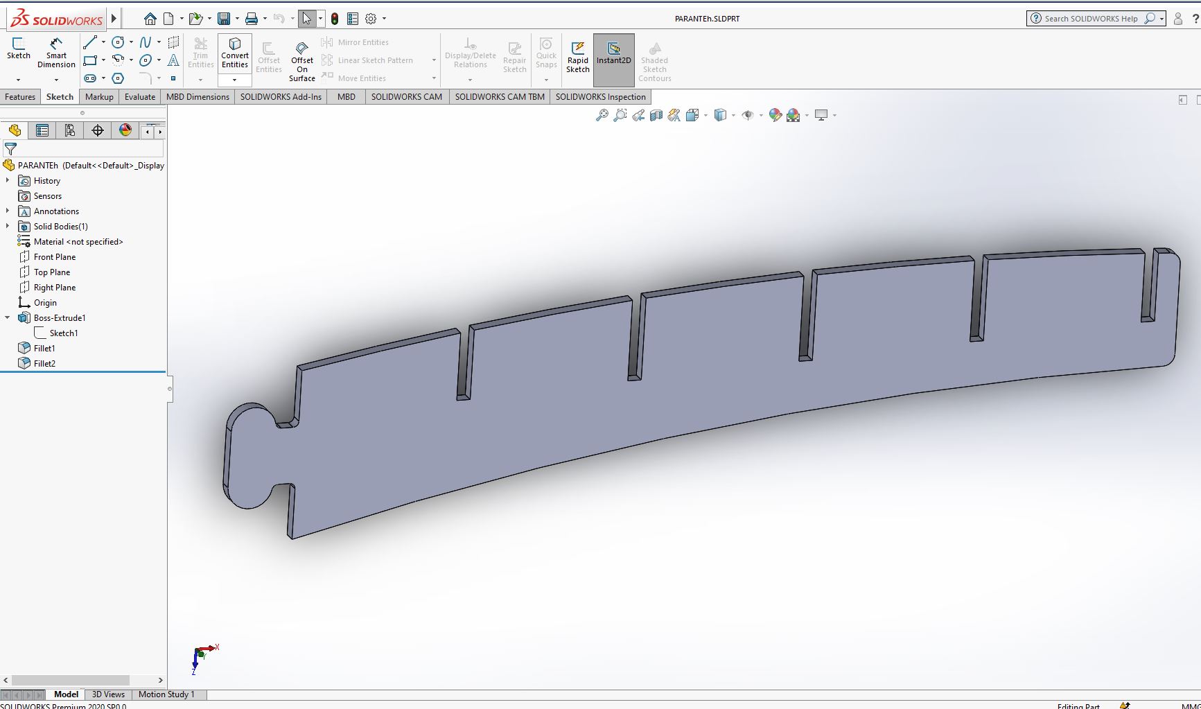
The design for the present task consists of a wall bookcase, the design was made in Solid Works, this to improve the ability to design in this tool, the design is parametric
to be able to change the thickness of the cutting material according to the need..
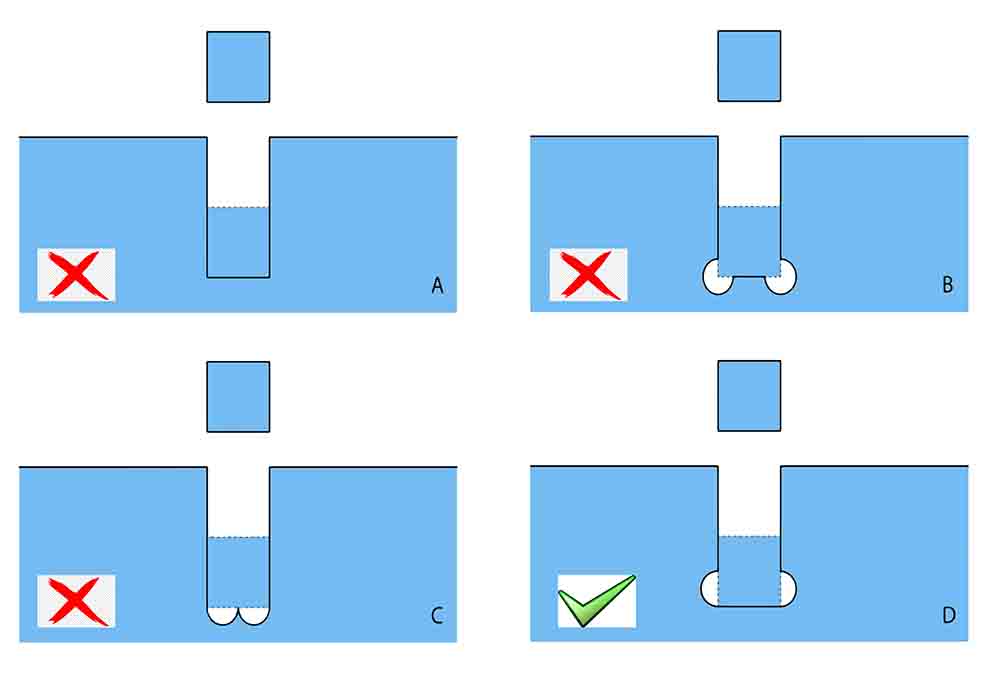
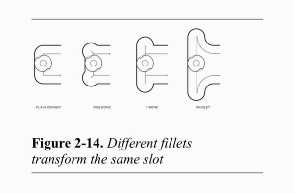
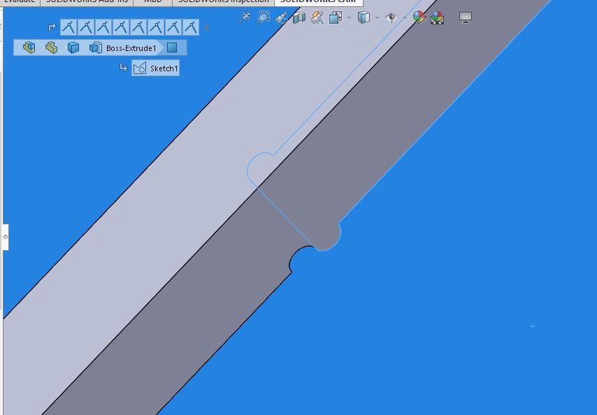
For joining the different parts of the wall bookcase
You need to understand the use of fillets on the inside corners. We have to understand that a round cutter will create a rounded corner and cannot make corners sharper
than its own diameter.
This peculiarity causes problems when assembling the pieces together, especially if it is used in a precision joint as a press fit.
You can find relevant information in the
following link
file download
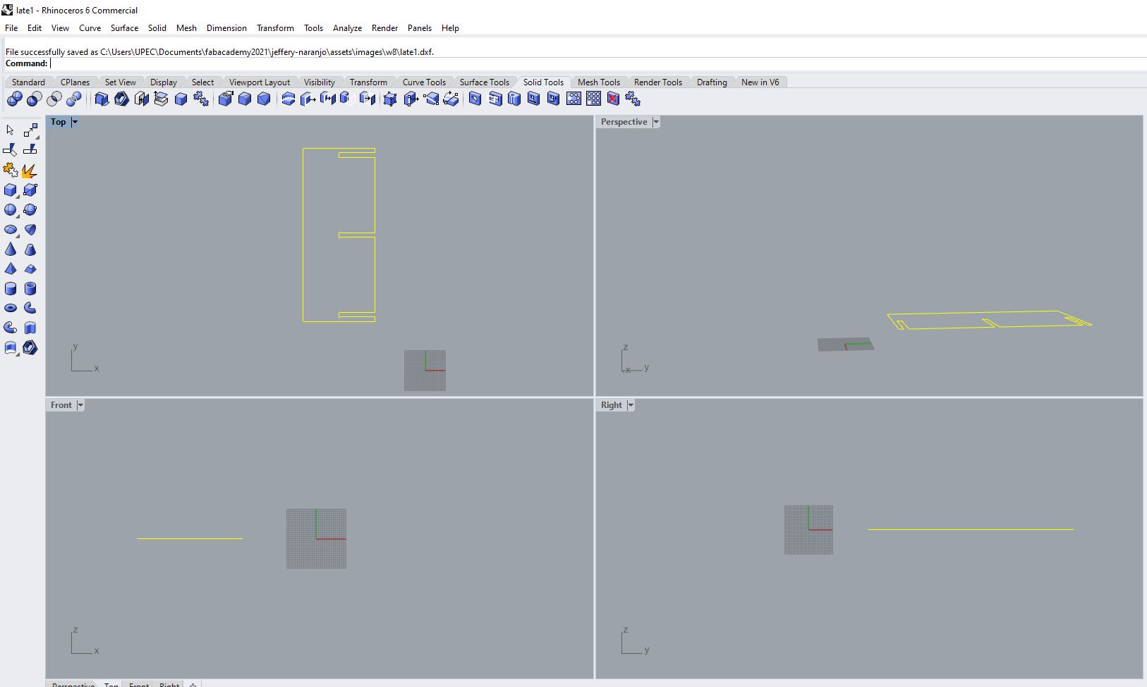
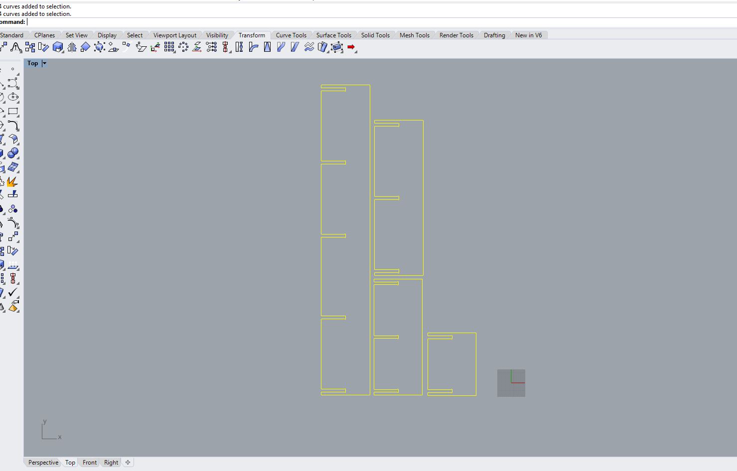
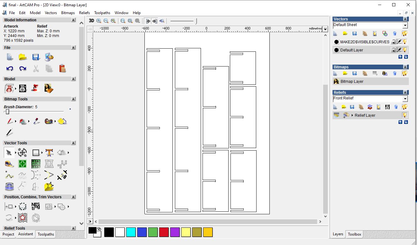
Importing the designs to rhino
The resulting designs made in Solid Works are a parametric image but in 3d. In order to generate the G-code we need these images in 2d, so they will be treated in Rhinoceros,
we will import the images and apply the Make2D command to them.
Make Something Big
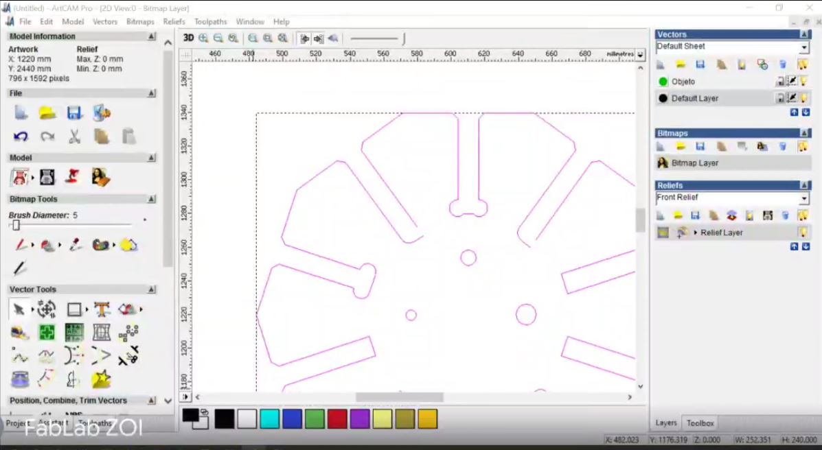
Preparing everything in the Artcam
ArtCAM is used in a variety of sectors from jewelry and coin minting, to the design and manufacture of architectural cornicing and facades. The common theme across
these sectors is the desire to produce intricate artistic forms with incredible detail that can then be quickly and easily machined or 3D printed.
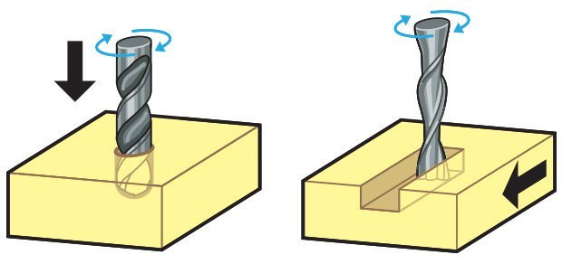
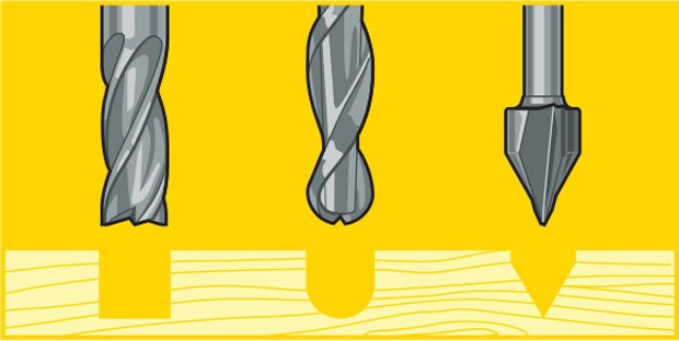
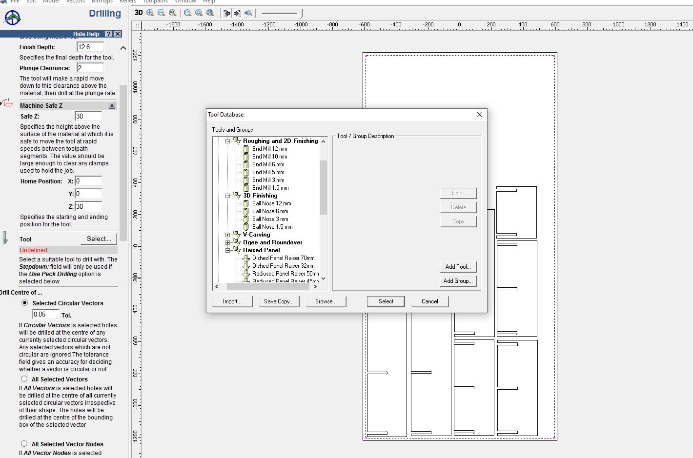
CNC Bits (cutting tools)
There are different types of milling cutters that can be used for specific different machining jobs.
- Drill bits are designed to drill verticallyinto material, making cylindrical holes.
- End mill bits are designed to cut cut along paths not just plunge vertically.
Test
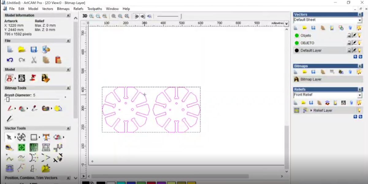
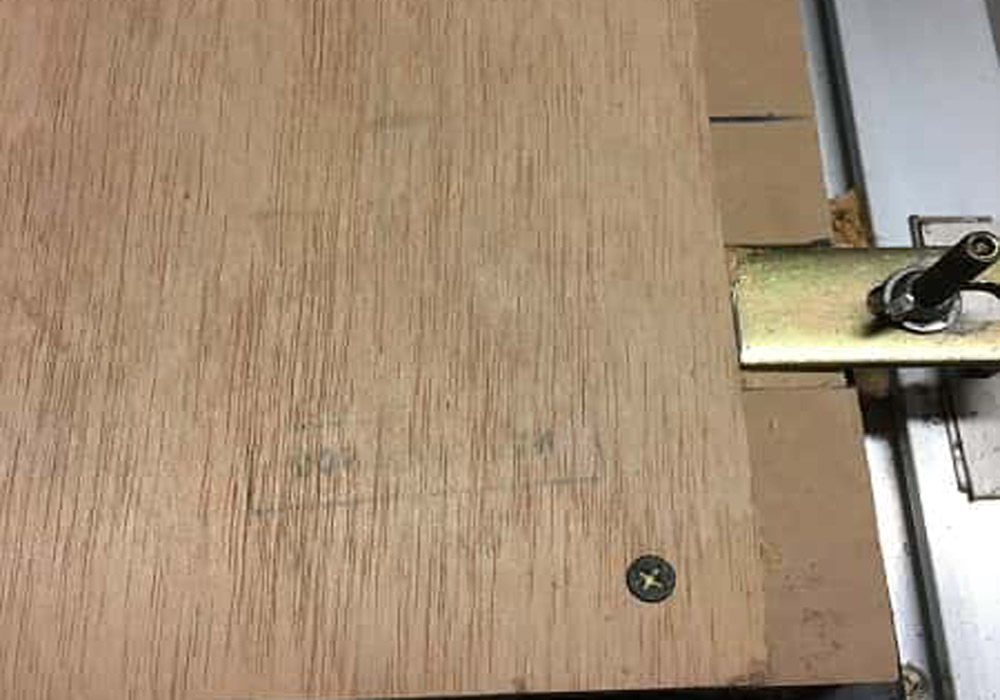
Before starting work, we are going to do a test with the material width and try to fit the pieces perpedicular together.
for this test Daniela download the file from Dani's repository (Dani is a former student) and edit it for 12mm plywood.
Measure the material (12mm plywood, 1200 x 2400 mm)
file download
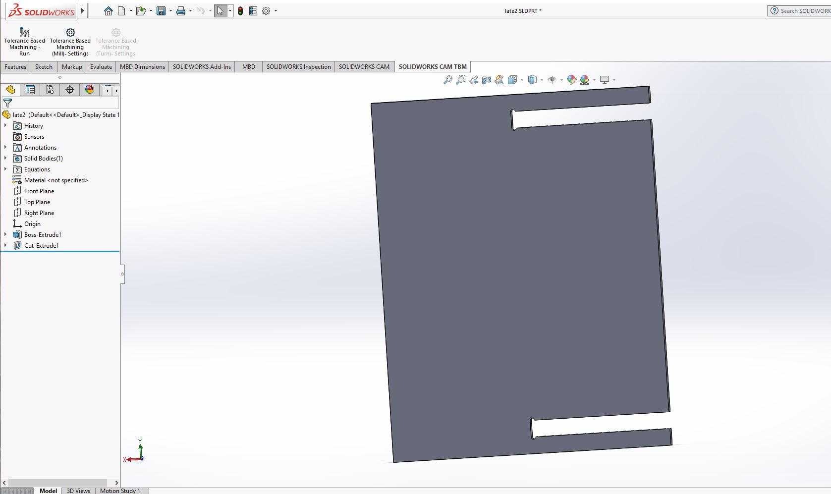
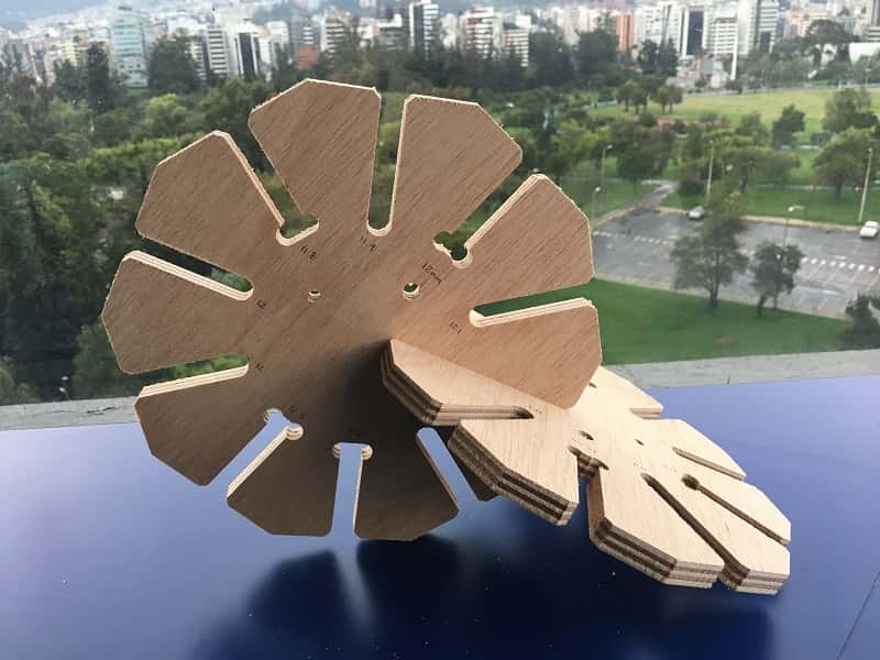
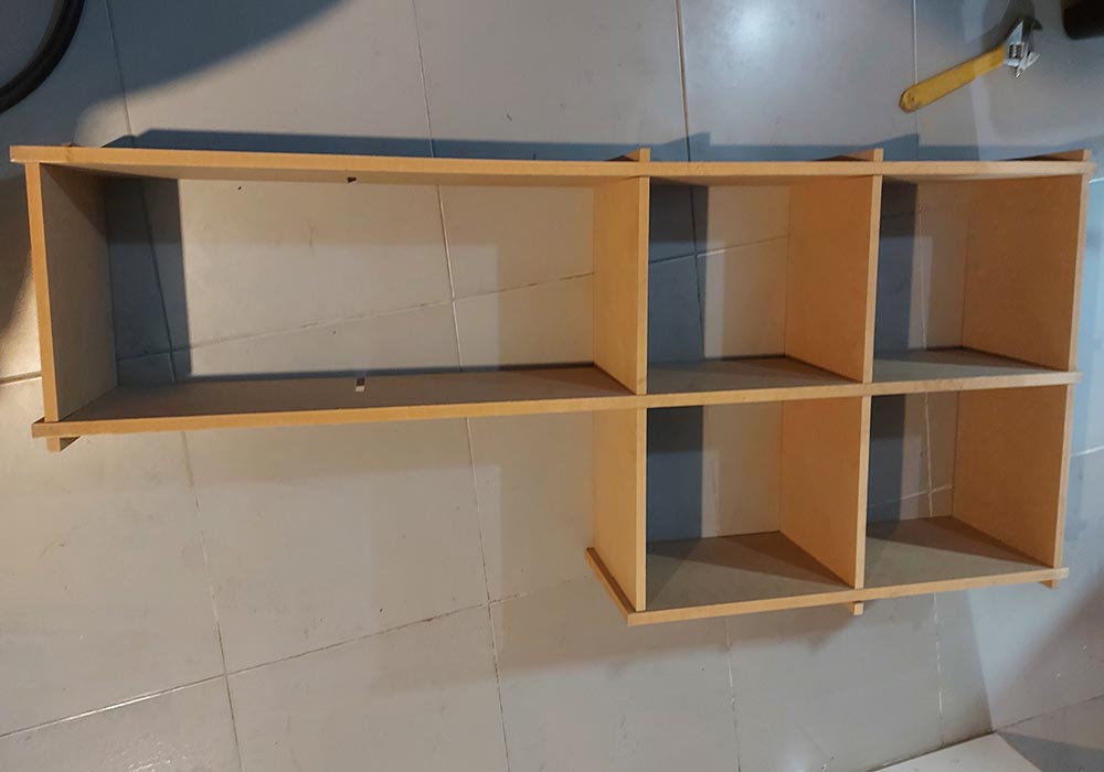
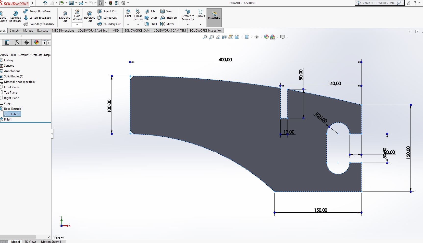
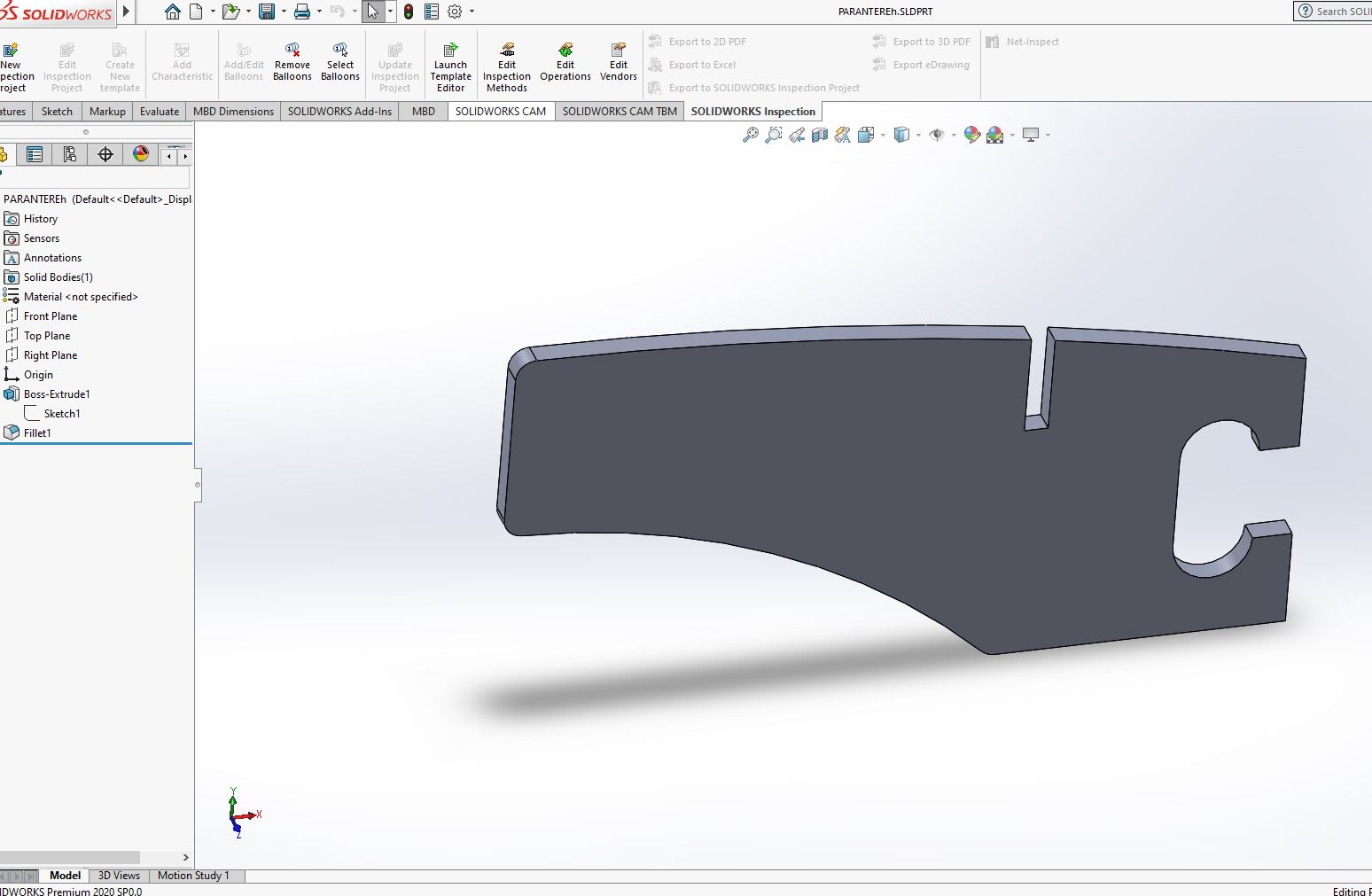
For the design of this week's assignment I design a wall cabinet, the truth is my very simple furniture,
since my specialty is not precisely design, I am a computer engineer
Preparing the cuts in the cnc
LAB's cnc machine
The machine avaliable at the lab was the following characteristics:
Model: 1325, 3 axes
Working area:1300x2500x200mm
Software:Artcam
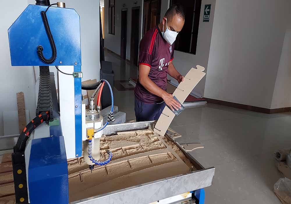
We locate the material in the CNC and proceed to secure the mdf on the sacrificial material, we place the end mill that we will use
in this case 1/8 ". Finally, it is necessary to verify that both the collet and the end mill are set to mm or inches. depending on the case
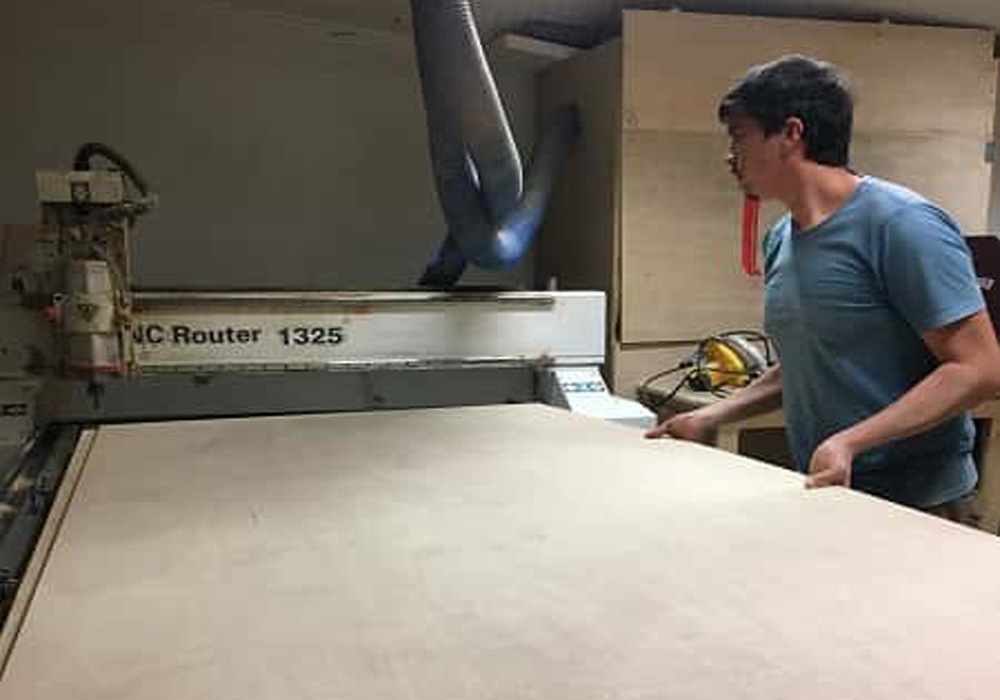
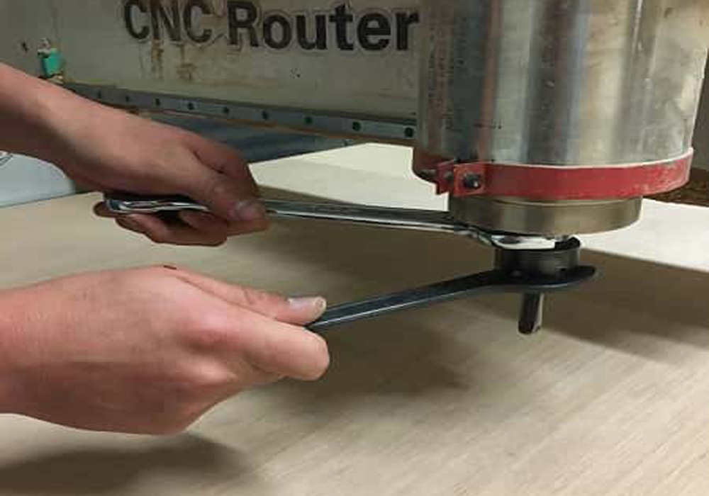
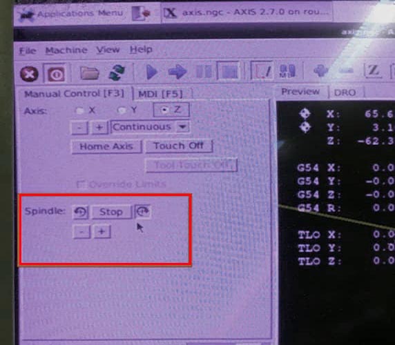
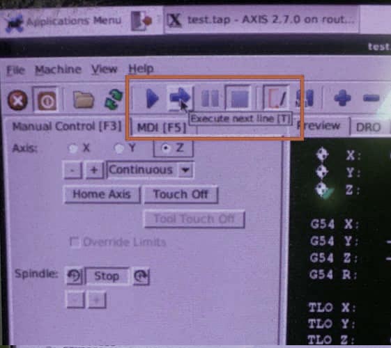
we load our file in the cnc program axisCnc, then through the keyboard we configure the zero point for both
x and y, finished the configuration of the origin point we turn on the spindle and finally we start the work with play
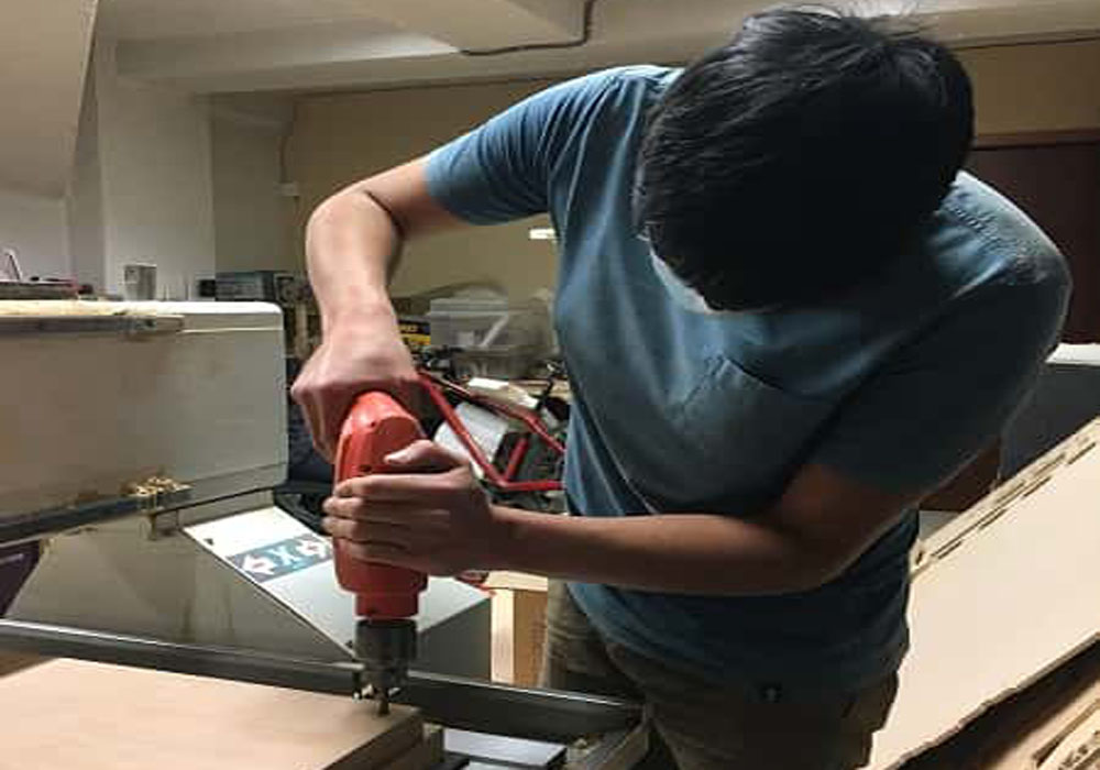
I open the file for the drilling, and we can use the keyboard to set 0 for x, y and z
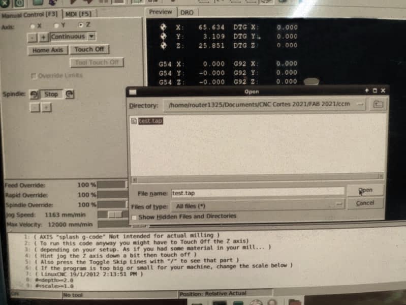
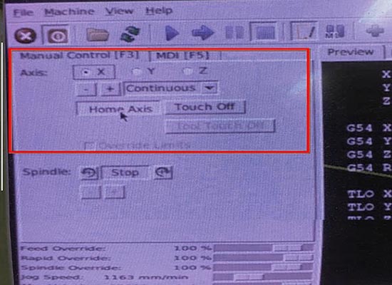
Turnon the spindle, and then run the code, to go step by step you can press "T" and to do it non stop press "S"
We can find the entire trial cutting process and the CNC workflow on the group page at the following link
Computer controlled machining
Make something big
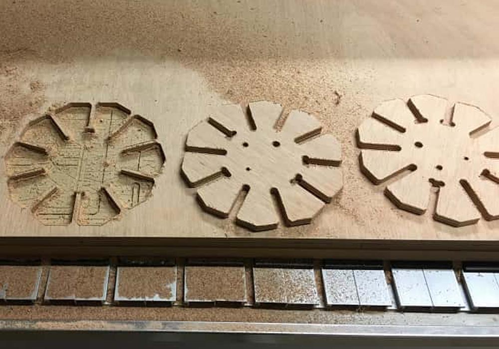
For this week's assignment, I sent my files to the laboratory in Quito, since I am doing the course remotely, virtual, ZOI sent me the
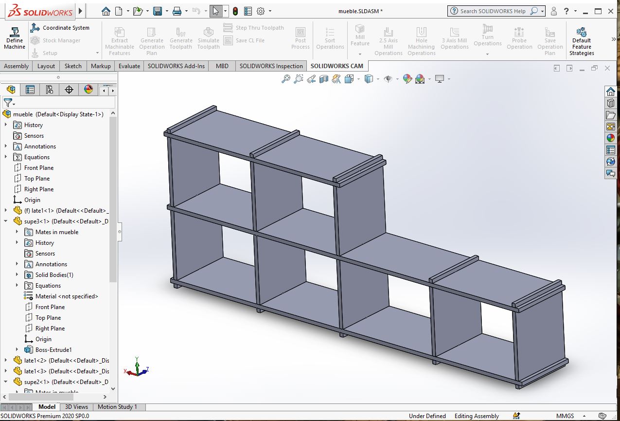
cuts to the city where I live, only up to this moment I could check if the parameters sent and the Measures configured in the material, as we
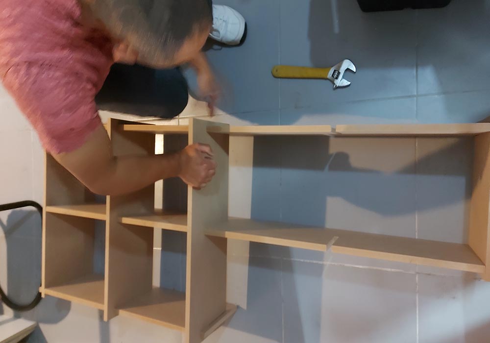
the dog bones worked correctly, in the end the furniture, although with a little difficulty, was assembled correctly, although as you
can see in the photo I did not get a piece
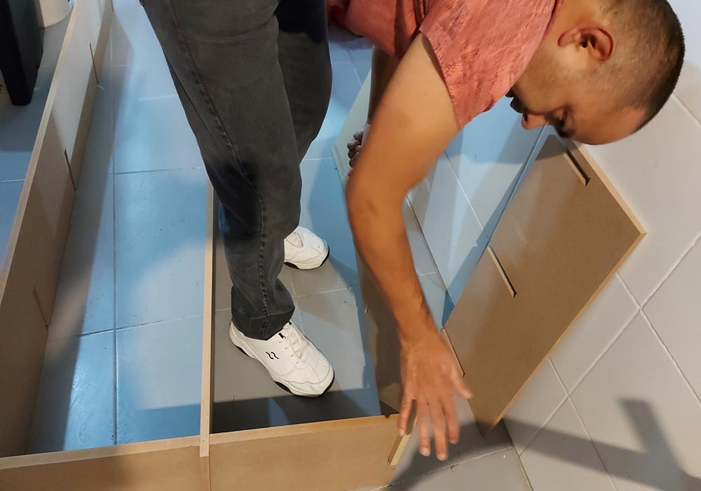
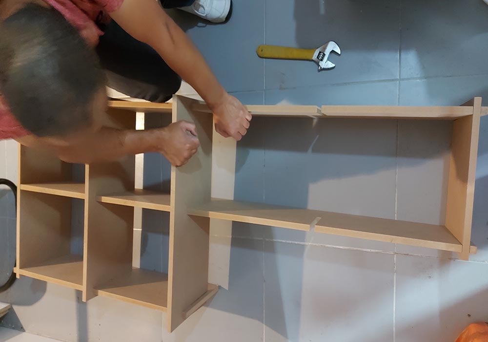
assembly is easy and the dog bones help the pieces fit together better
You can download the files in the next links
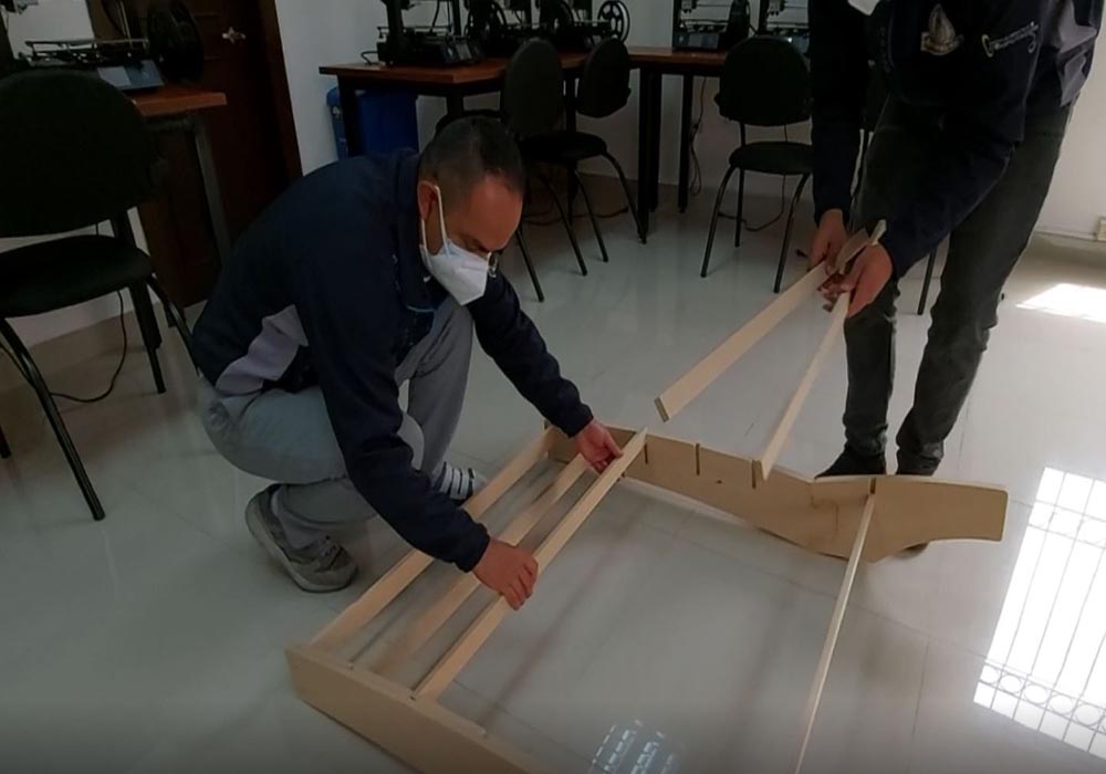
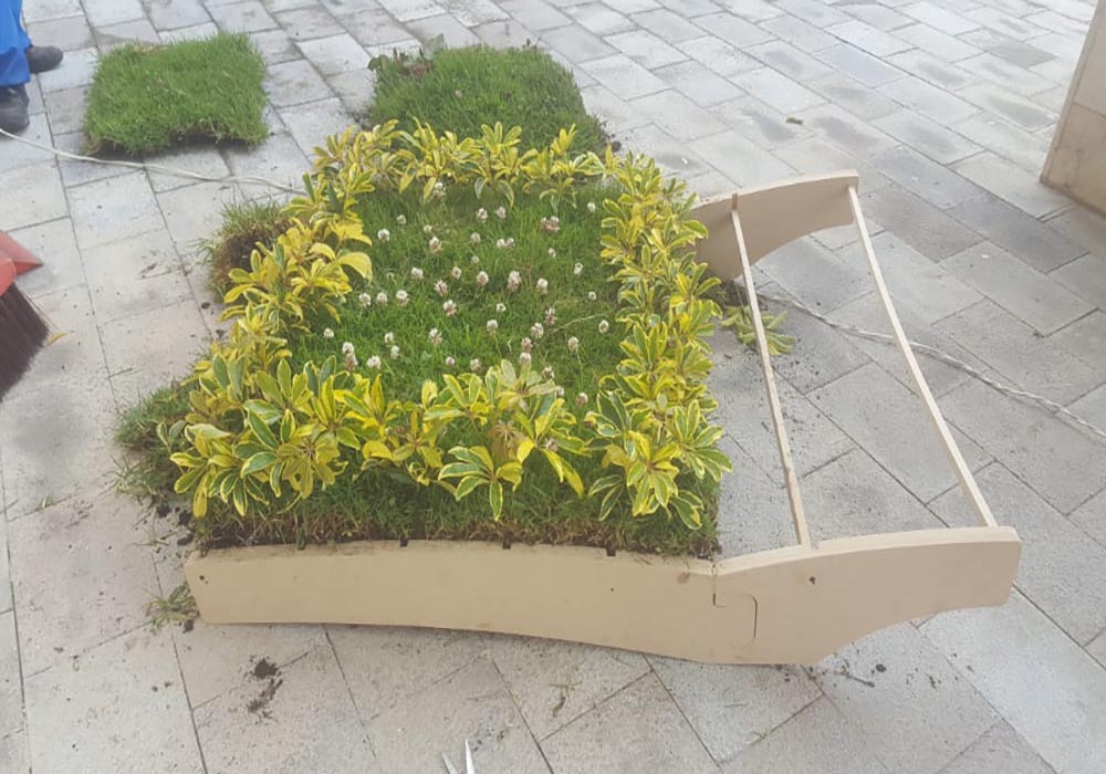
Designing and building the structure of the final project
For the design of the roof structure of the sustainable bus stop, the Solid Works tool was used.
Due to limitations in the cnc work area, the design of the structure was carried out as two separate elements, in the same way,
having only 12mm mdf material, it was decided to join two pieces to have structural resistance due to the weight of the substrate and the plants
To support all the elements of the roof, a few pieces were designed and manufactured in the internal arms
of the stop to place the pergolas that will support the substrate and the plants.
You can download the files in SolidWorks in the following link
SolidWorks files
finally finished the design work, the pieces were exported in stl and dxf format in order
to then be able to generate the G-code files to be manufactured with the Cnc 6090
You can download the files STL in the following link
STL Files
You can download the files DXF in the following link
DXF Files
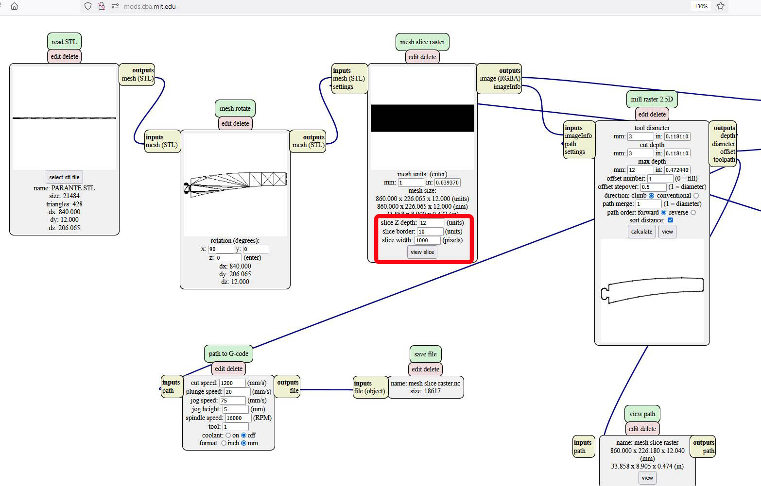
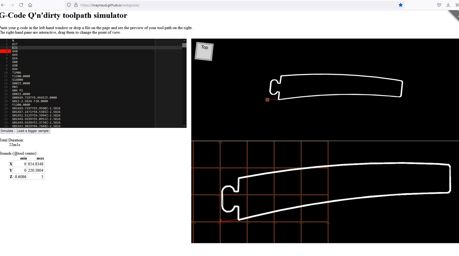
once we have the stl files we proceed to generate our files with the Mods tool, for this we will use a 3mm cnc milling cutter
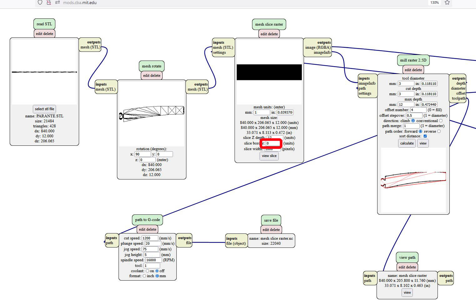
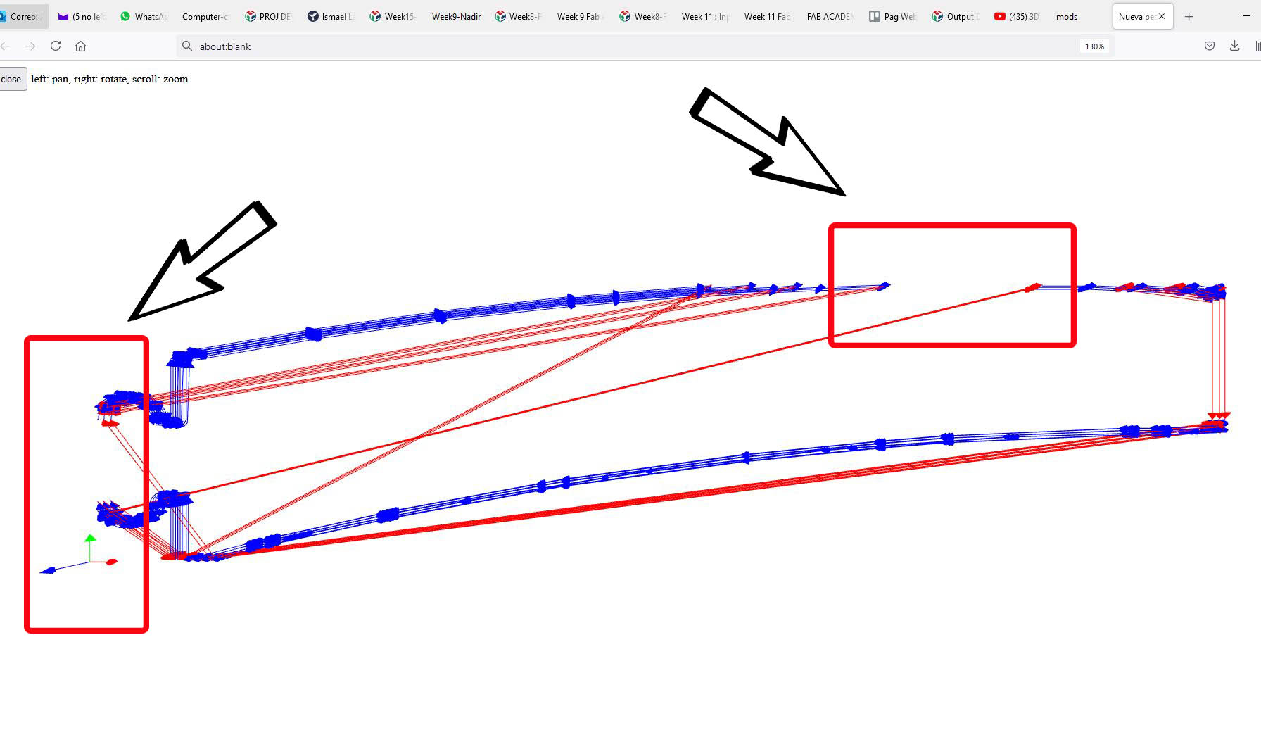
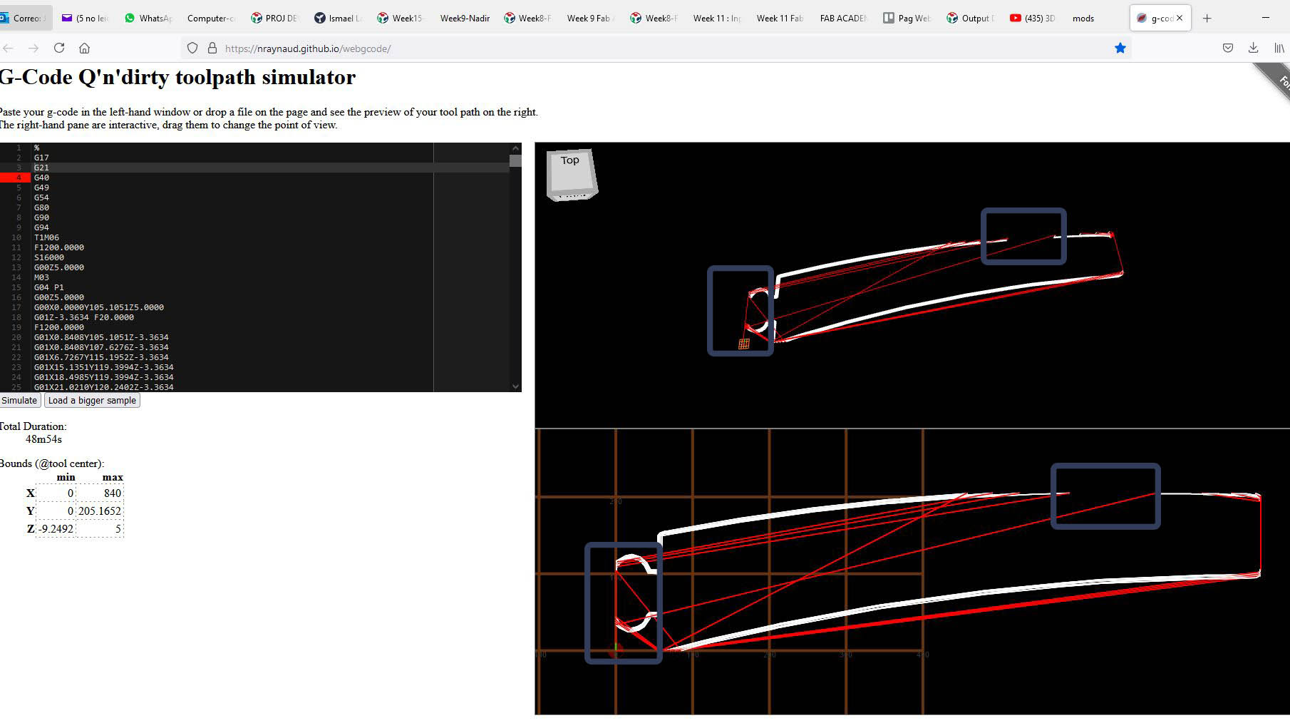
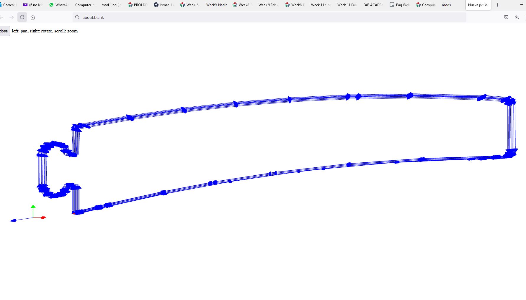
As we can see in the first generated file there are errors in the G-code, we have incomplete sections, this is solved when configuring in the MODS
in the third box giving a parameter in the slice border, in my case I have set 12mm to the edge
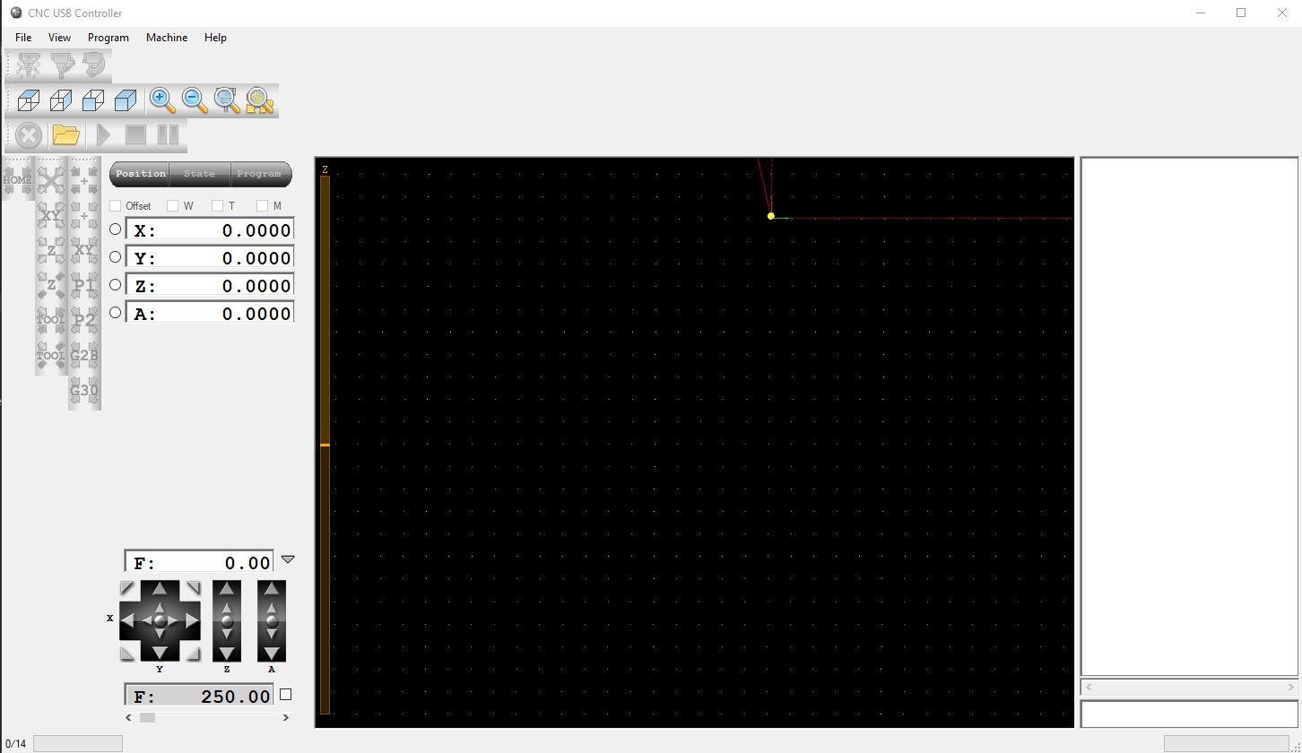
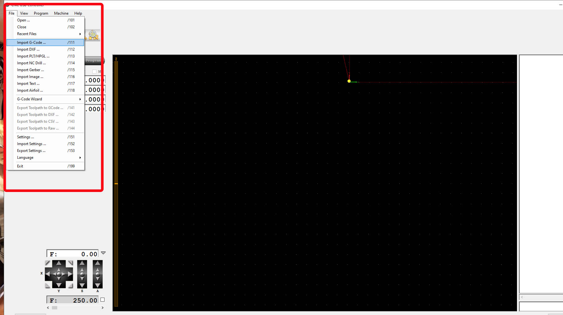
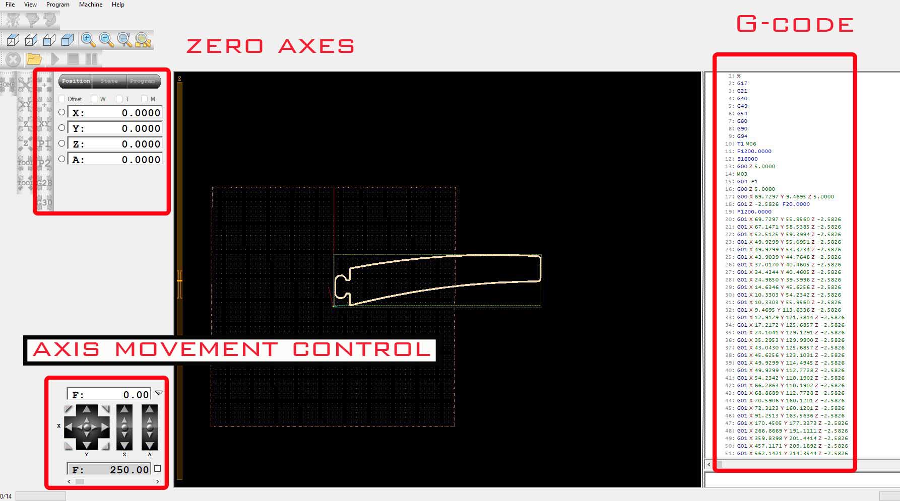
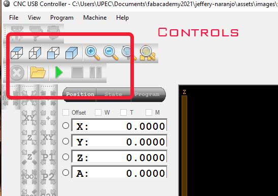
Finally, we send our file containing the G-code codes to the CNC software, in our case we will use the CNC USB Controller software,
a program that is very easy and intuitive to use.
here we import our G code, we place the tool at the zero point by using the axis movement control and finally we press play to start the job
below we can see the final result and some videos of the routing process of the material
 |
|
|
Hero photo