Assignment
GROUP PROJECT:
Test runout, alignment, speeds, feeds, and toolpaths for your machine
INDIVIDUAL PROJECT:
Make something big
What I did
- Designed furniture in fusion360
- Cut the dsign in Shopbot and assembled it.
- Tested various parameters of machine
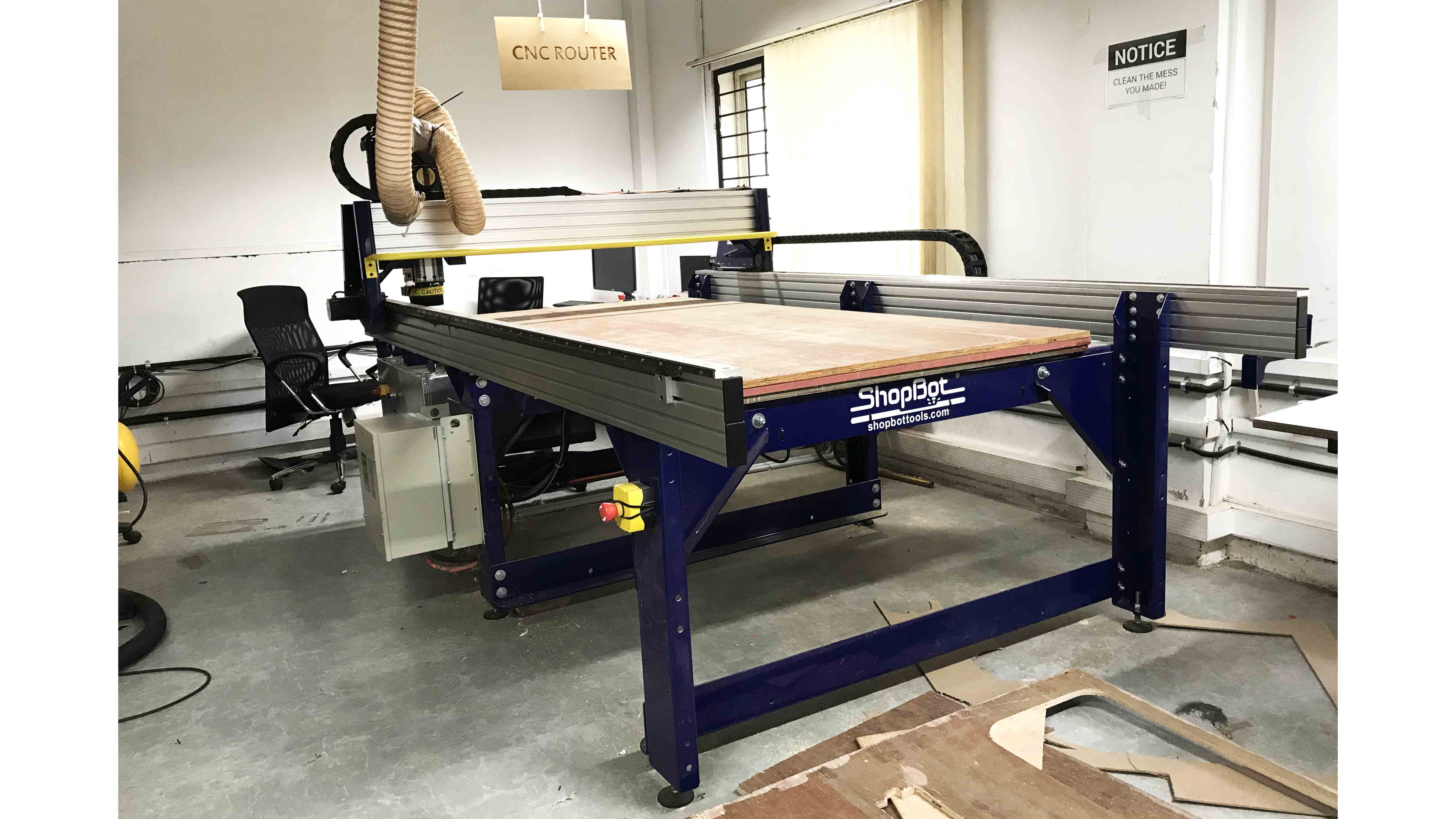
SHOPBOAT
CNC stands for Computer Numeric Control it is a process used in the manufacturing sector that involves the use of computers to control machine tools. Tools that can be controlled in this manner include lathes, mills, routers and grinders.
Different Bits
Drill Bits vs End Mills
CNC machining is a subtractive process that uses rotational cutting tools called “end mills” to remove material. An end mill, while similar in appearance to a drill bit, is far more versatile. However, in practice the terms “bit” and “end mill” are often used interchangeably.
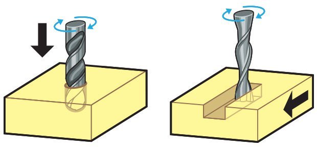
Here’s the key difference. Drill bits are designed to plunge directly into material, cutting axially and creating cylindrical holes. End mills are typically used for horizontal carving and cut laterally. Additionally, most mills are “center-cutting,” meaning they are able to cut both axially and laterally. This is due to cutting flutes that extend to — and protrude from — the end face and enable plunge cutting. To minimize tool breakage and stress on the material being cut, most CNC software will “ramp” the end mill slowly into lateral cuts.
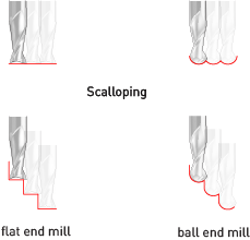
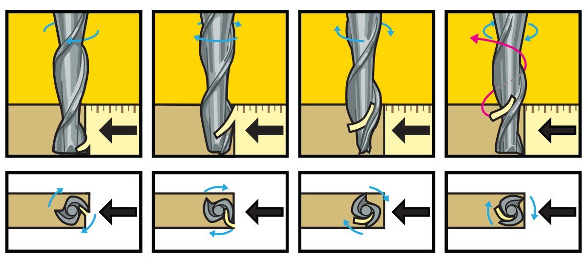
Tip Shapes and Applications Choosing flat end mill vs. a ball end mill will determine the characteristics of the tooling marks (or lack thereof) on your model. Most jobs will benefit from strategic use of multiple size and shape tools for milling different features. End Mills are often used for roughing and 2D cutting and V-Bit and Ball Nose cutters are often used for finishing operations. Up-cut, down-cut and compression cut determine the way the chips (cut material) are ejected and the smoothness of the surface. With an up-cut end mill, the chips will be ejected upward and the bottom of the material will be smooth. The down-cut end mill is the reverse by puching the chips downward and the top of the material is smooth. The compression end mill creates a smooth surface on top and bottom, which is perfect for pre-laminated woods.
There are up-cut, down-cut, compression cut end mills with varying numbers of flutes. End mills are intended to cut horizontally. Up-cut, down-cut and compression cut determine the way the chips (cut material) are ejected and the smoothness of the surface. With an up-cut end mill, the chips will be ejected upward and the bottom of the material will be smooth. The down-cut end mill is the reverse by puching the chips downward and the top of the material is smooth. The compression end mill creates a smooth surface on top and bottom, which is perfect for pre-laminated woods. End mills come in a variety of shapes. The most common are flat end mills and ball end mills. Flat end mills will cut flat areas with no scallops. However, they leave a terrace-like scallop on non-flat surfaces. Ball end mills will leave smaller scallops for the same stepover value on sloped surfaces, but they will also leave scallops on flat areas. Flat end mills can be Center Cutting and Non Center Cutting: Center cutting square endmills are essential for plunge milling.
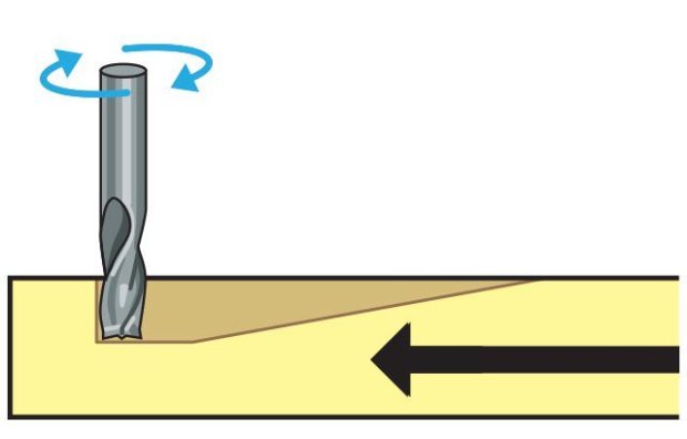
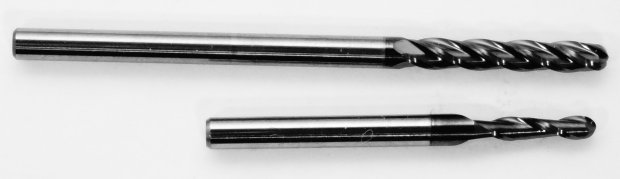
Each end mill tip shape is designed for a particular purpose. Some common cutter shapes are ballnose, fish tail, surface planing, v-carving, and straight.Ballnose mills produce a rounded pass and are ideal for 3D contour work, while fish tail cutters will produce a flat surface. V-bits produce a “V” shaped pass and are used for engraving, particularly for making signs.
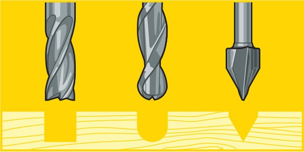
The diagram above shows the difference in clearing path shape between a fish tail, ball nose and V tools. Ball nose mills are often selected when doing 3D contouring because their rounded edge reduces jagged steps when cutting several stepped layers. Ball nose mills can also be used to cut wide paths with rounded edges by reducing the step over amount (overlapping distance between) between passes. By overlapping steps, the central scallop shown in the diagram is eliminated.
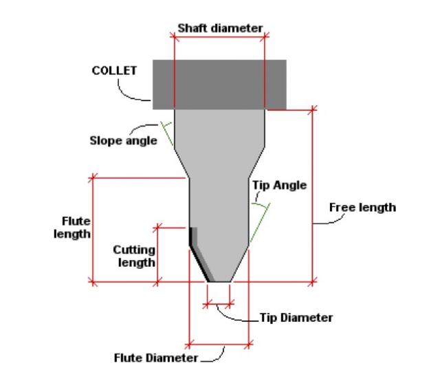
Flutes and Chipload
Flutes and Chipload
Flutes are the helical grooves that wrap around the sides of the end mill. Each flute has a single tooth with a sharp cutting edge (although there can be more than one) that runs along the edge of the flute.
As the tooth cuts into the wood, each flute whisks away a small section or “chip”. The fewer the flutes, the more material that is ejected with each tool rotation. The overall cutting depth should never exceed the length of the flutes on an end mill. If cutting deeper than the length of the flutes, the tops of the flutes will be blocked and chips won’t clear, building up heat and reducing tool life
Group Assignment
In this week group assignement is, We need to test cut a design to understand about the test runout, alignment, speeds, feeds, and toolpaths for our machine. everyone is involved in designing and cuting out the design. Here is the screenshot of the design below.
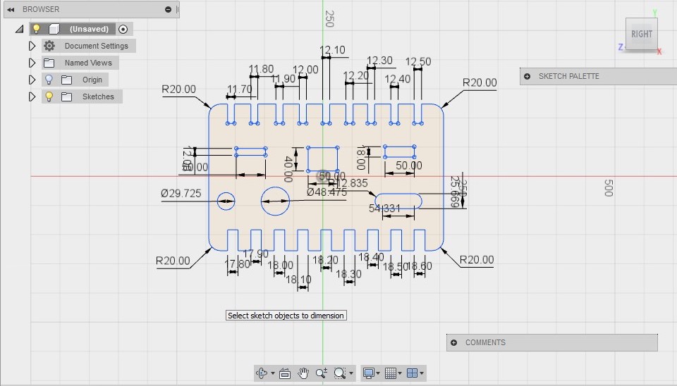
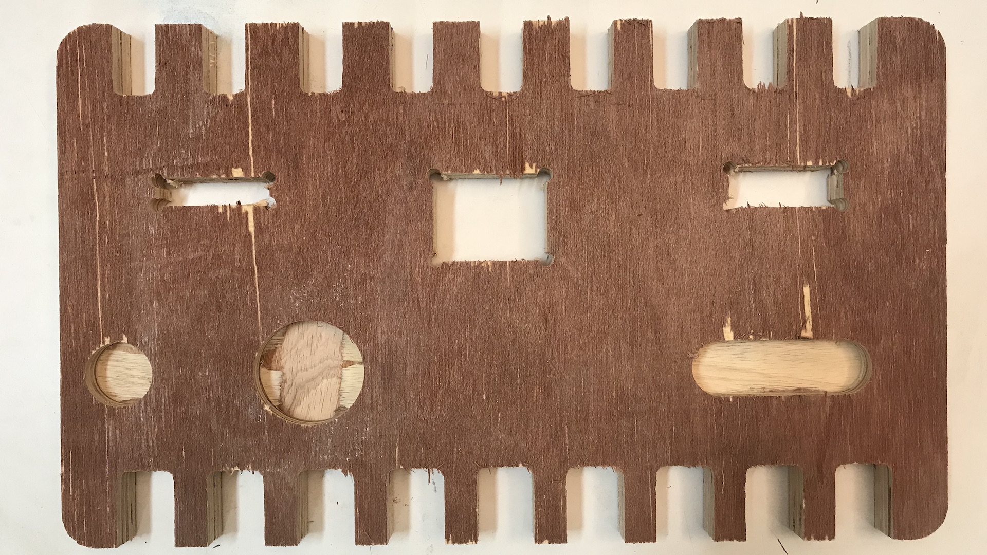
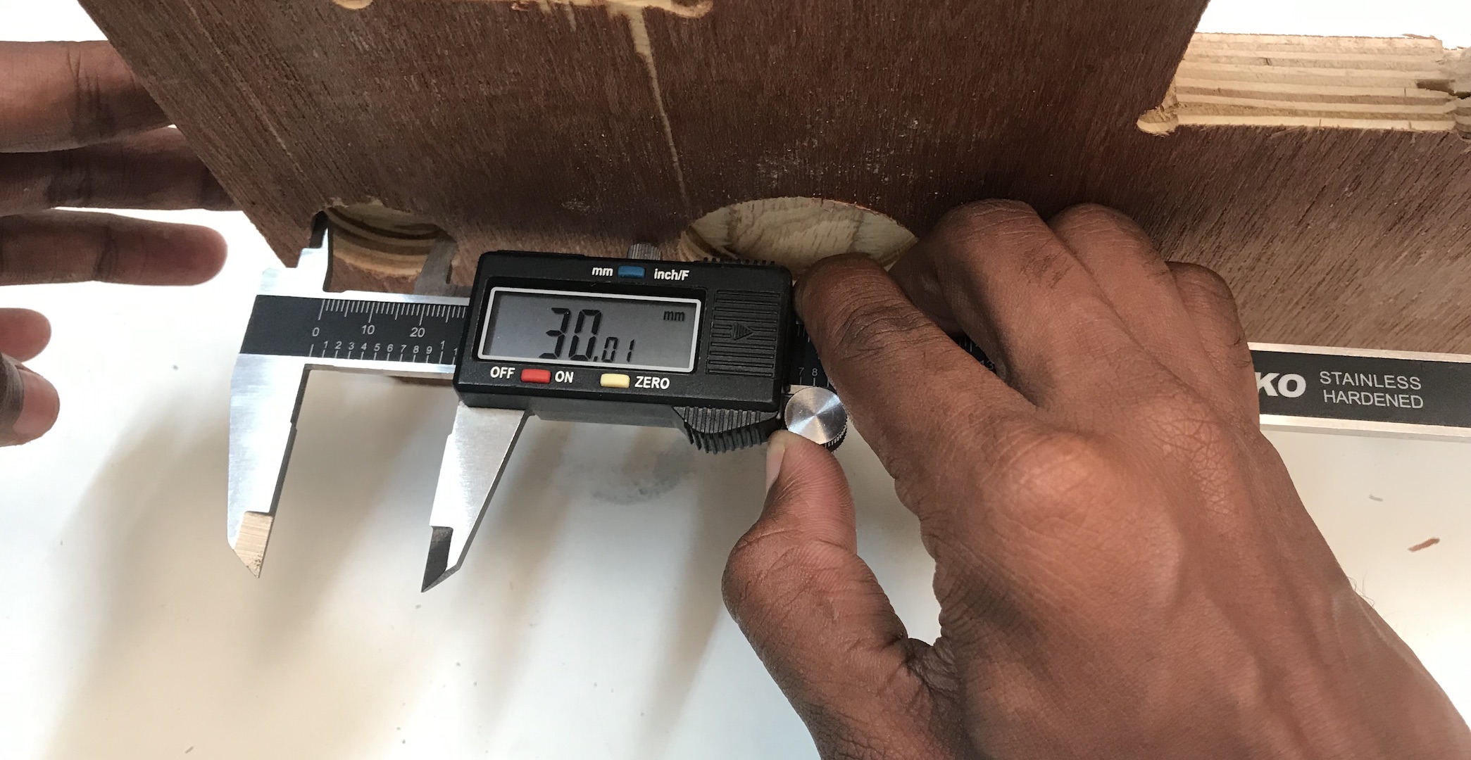
This was our group assignment to find the press fit dimension for the 12mm and 18 mm plywood .So we cut slots from 18.90 to 17.80 in steps of 0.1mm and for 12mm from 11.70 to 12.50 in steeps of 0.1 mm. We found out that the right fits comes somewhere near 18 mm and 11.7 mm. The material thickness does vary a bit with temperature ,moisture etc.
Plywood Stool
I have decided to make a stool with 1 meter height. I started designing in fusion 360. 18mm plwood is ideal for my use. and that is the strongest available plywood in our lab.
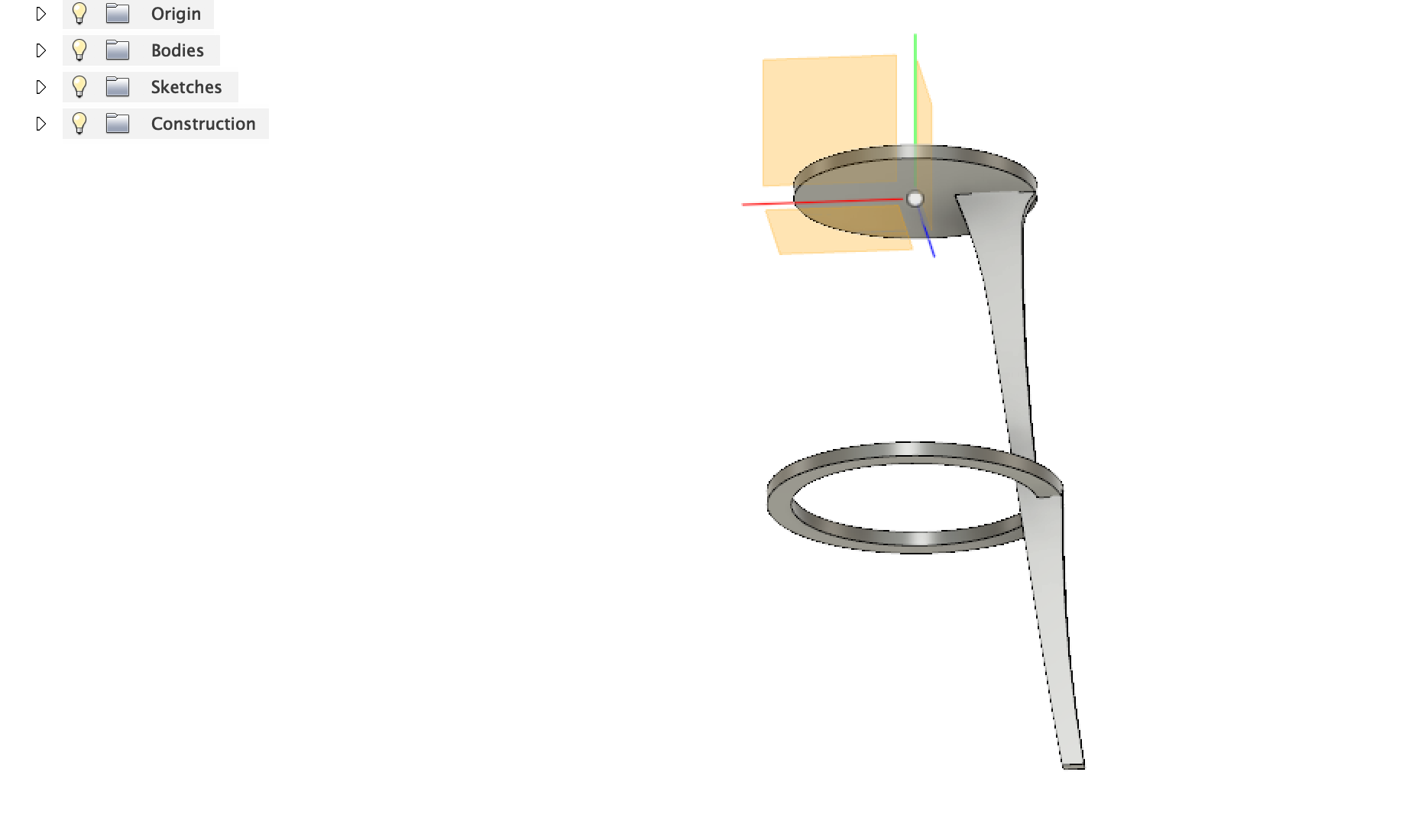
First I have extruded circular disk, and projected a plane from the surface of the disk and again drawn a ring.
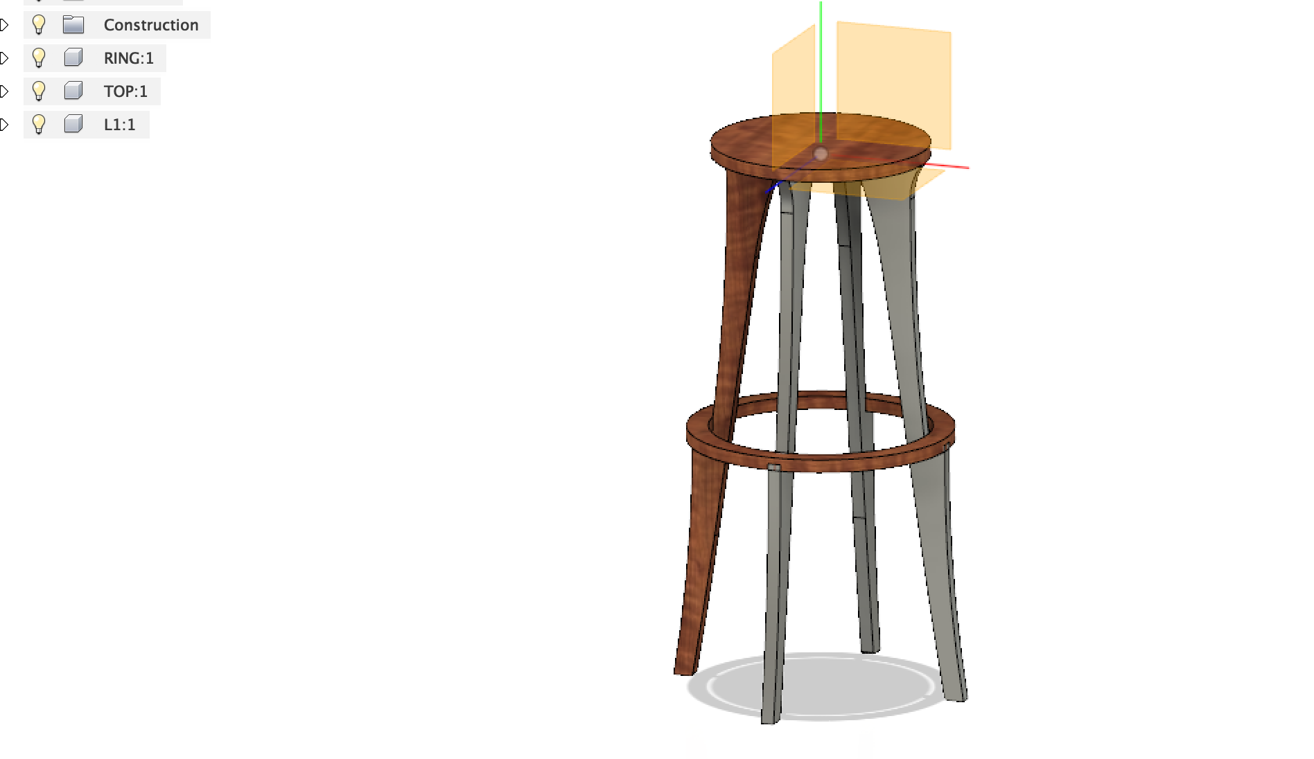
I wanted the legs as thin as possible for the minimalist look. After the design is done, changed the texture to wooden finish.
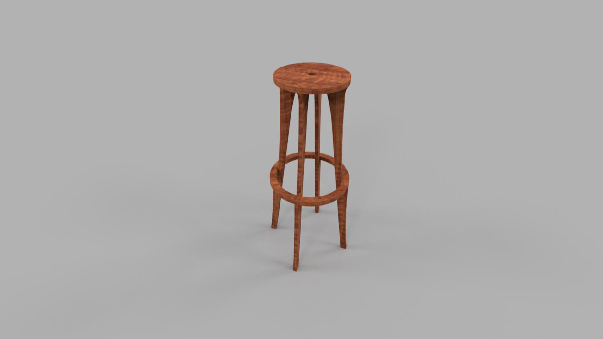
This is the rendered model after the final design.
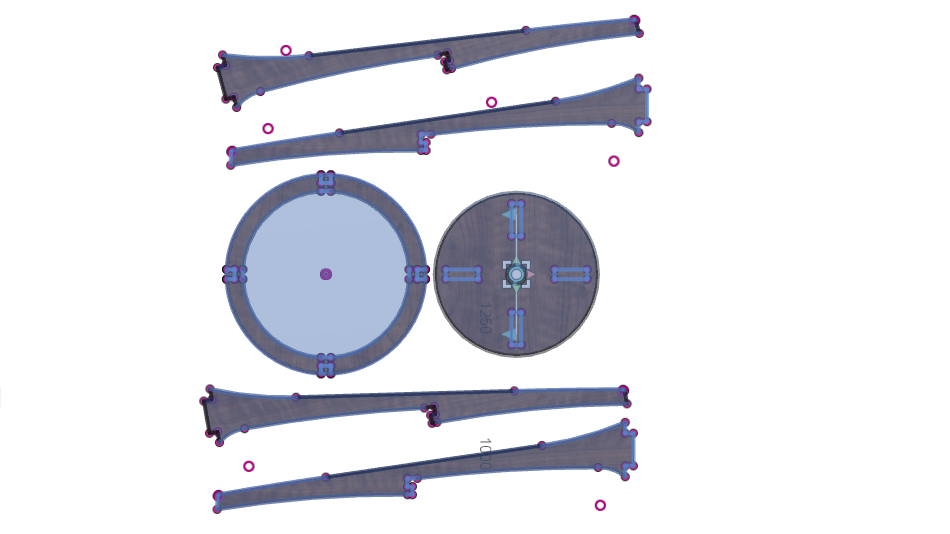
Next step is to dismantle the parts and make the DXF format for milling.
Cutting using shopboat
Safety first
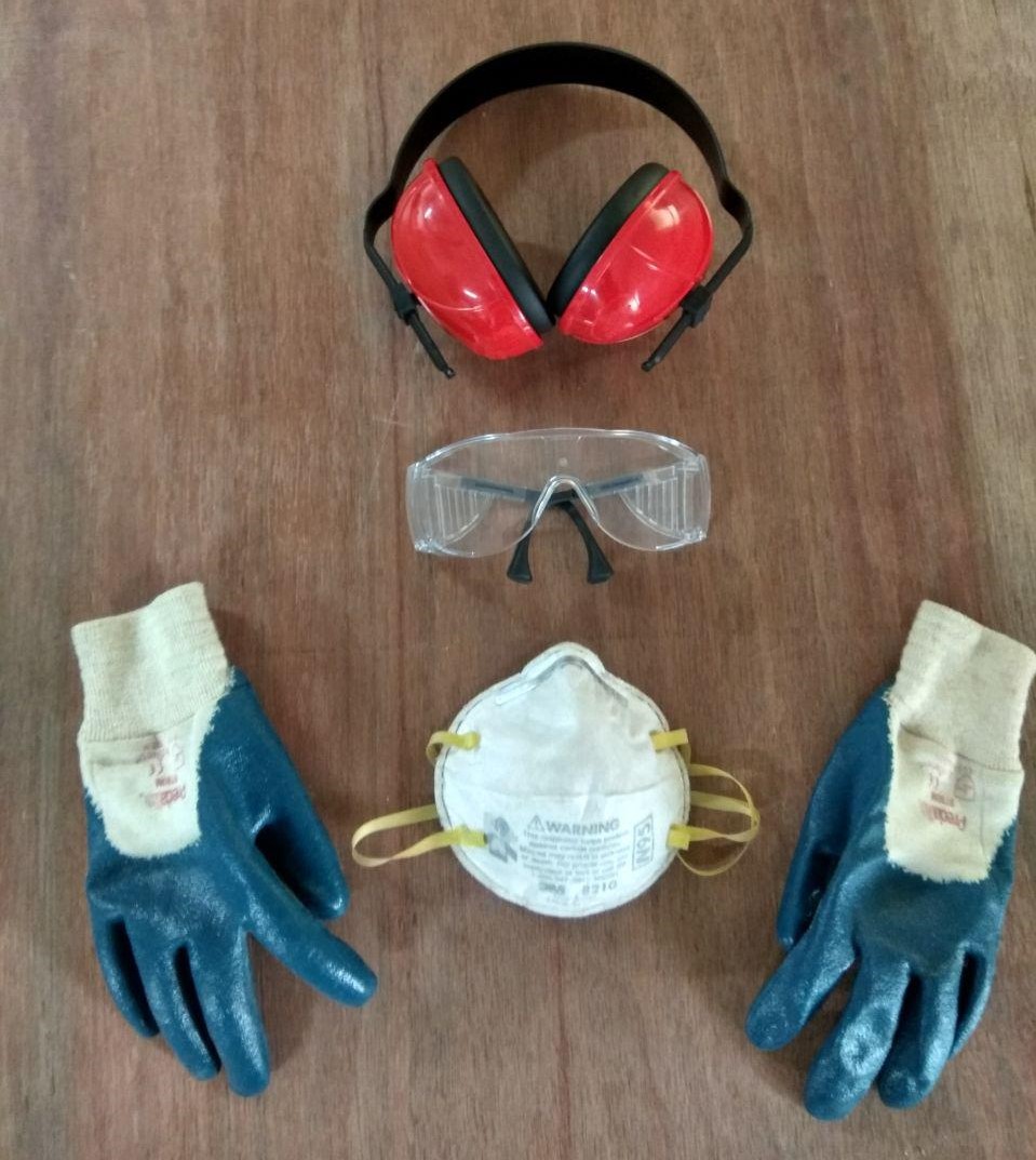
Make sure to use all safety equipments before operating such a huge machine.
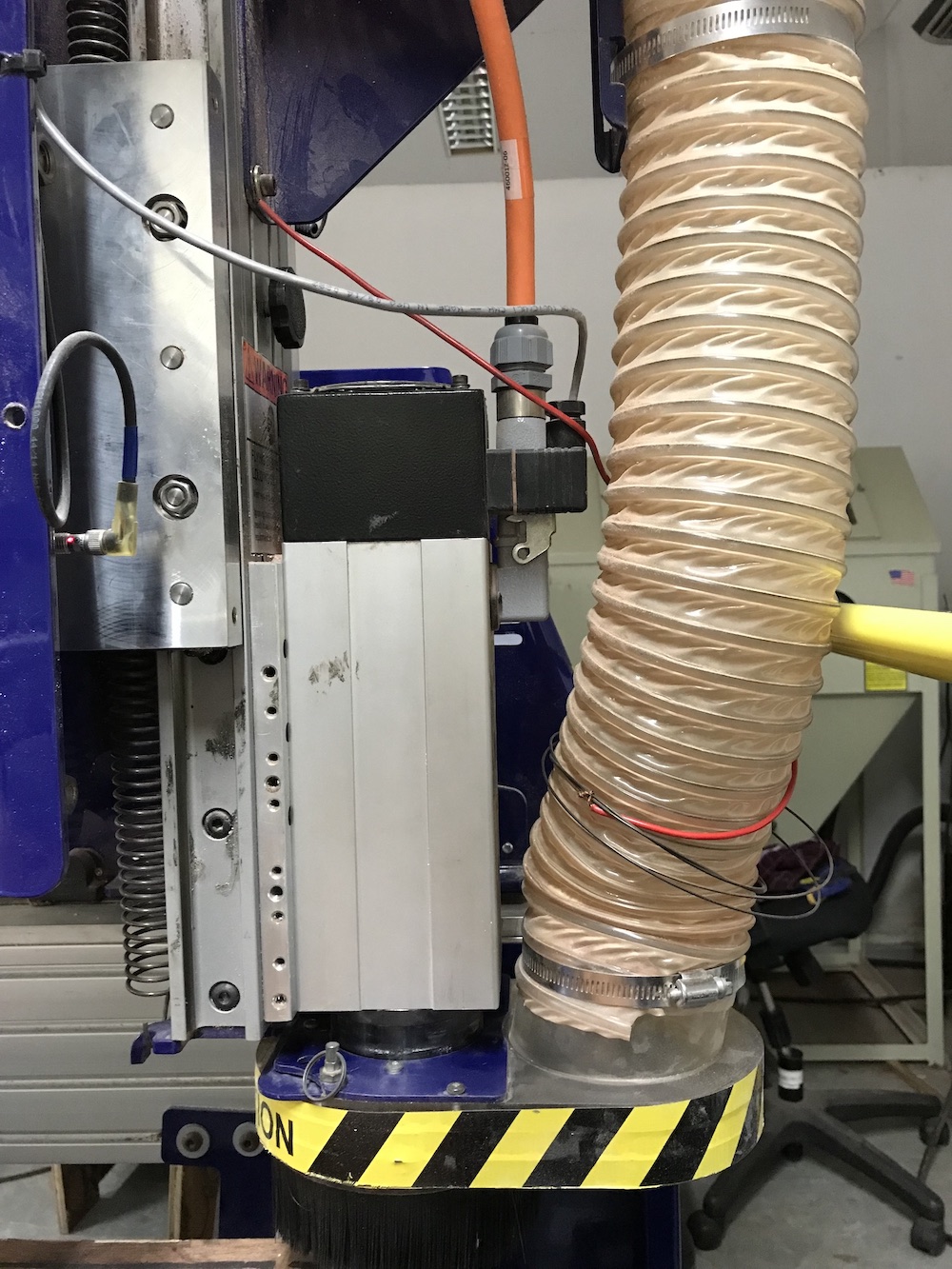
Collets and Cover Nuts
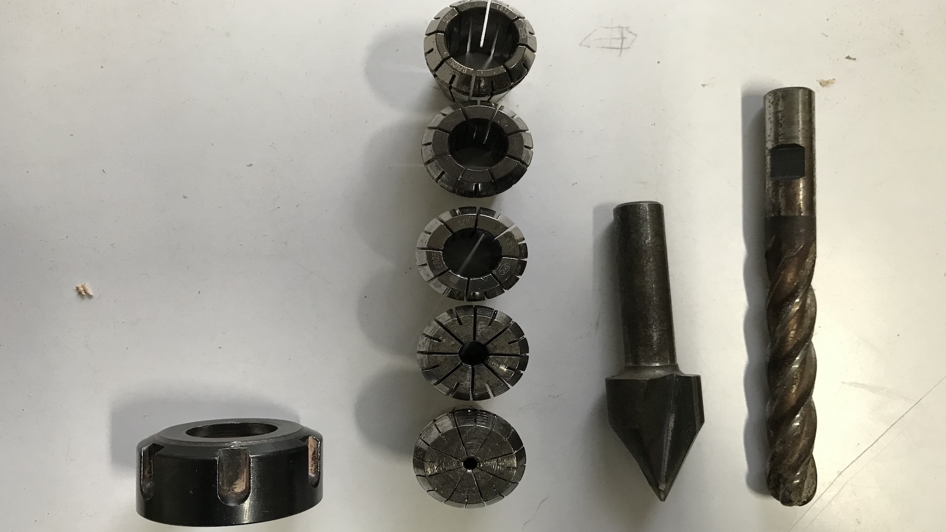
A collet is a subtype of chuck that forms a collar around an object to be held and exerts a strong clamping force on the object when it is tightened. It may be used to hold a workpiece or a tool. We are using ER25 collets, ER collets are slotted (alternately) from both ends and therefore compress onto the cutter along the whole length of the collet when tightened. This not only provides a better grip on the cutter shank but also allows some variation (typically 1mm) in shank sizes that may be used in a single collet. The smaller size collets are best used to hold cutters no more than 0.5mm below the nominal size. Collets are inserted into the covernut.
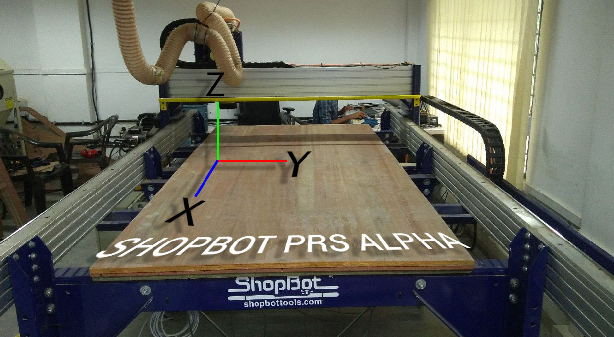
Shopbot is a 3 axis machine the Z axis is perpendicular to the bed .The X and Y axisis are the length and the breadth of the machine respectively.To have a riggid supporting layer on the bottom of the workpiece we will place an additional piece of plywood above the bed called sacrificing layer .The sacrificing layer also protect the millig bit from damage by avoiding unwanted intereference with the metal body.
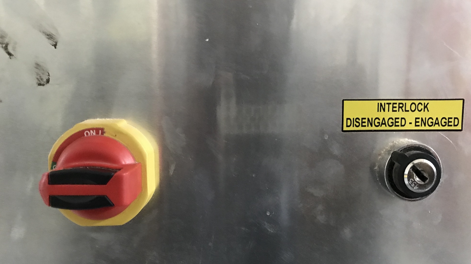
Every machines does have a ON/OFF switch. You can find the ON/OFF Knob in the right side of the shobot. Just turn the red color knob to ON or OFF the machine
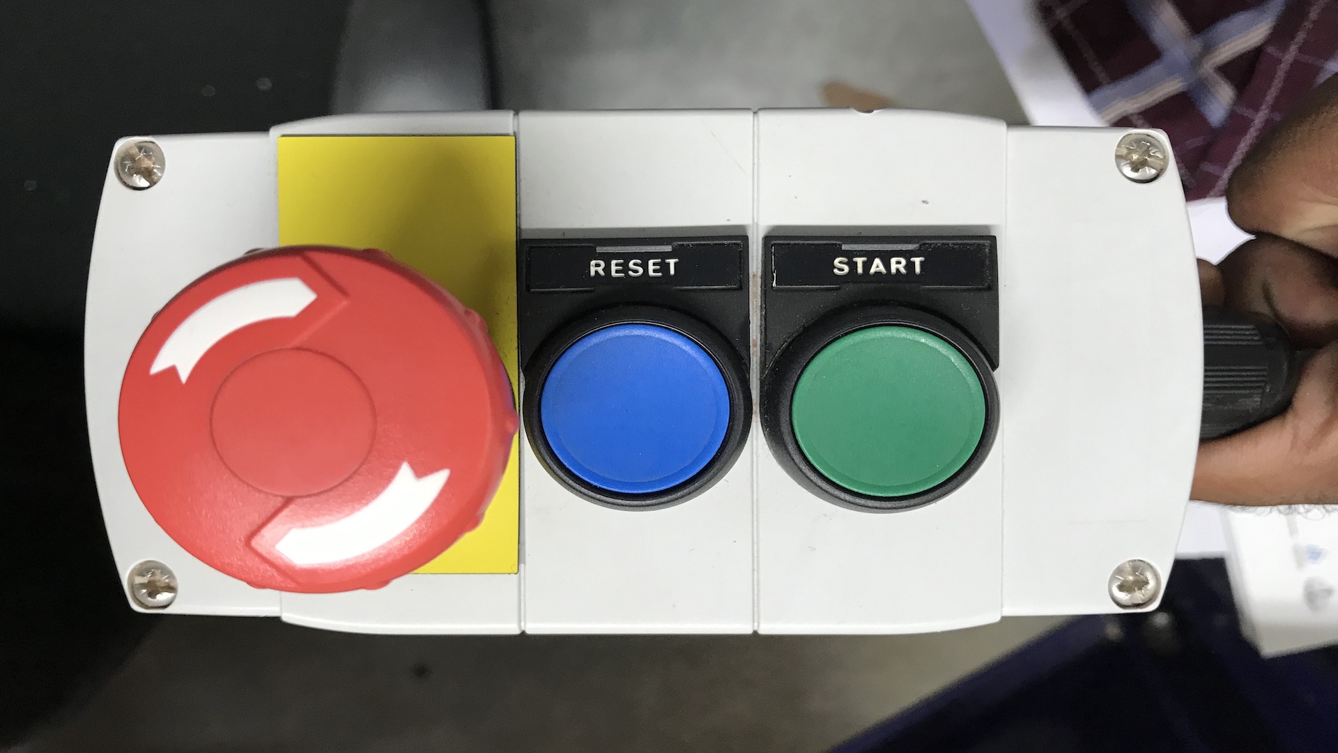
Shopbot has a wired remote which consist of an emergency button,A reset switch and a spindle start button.
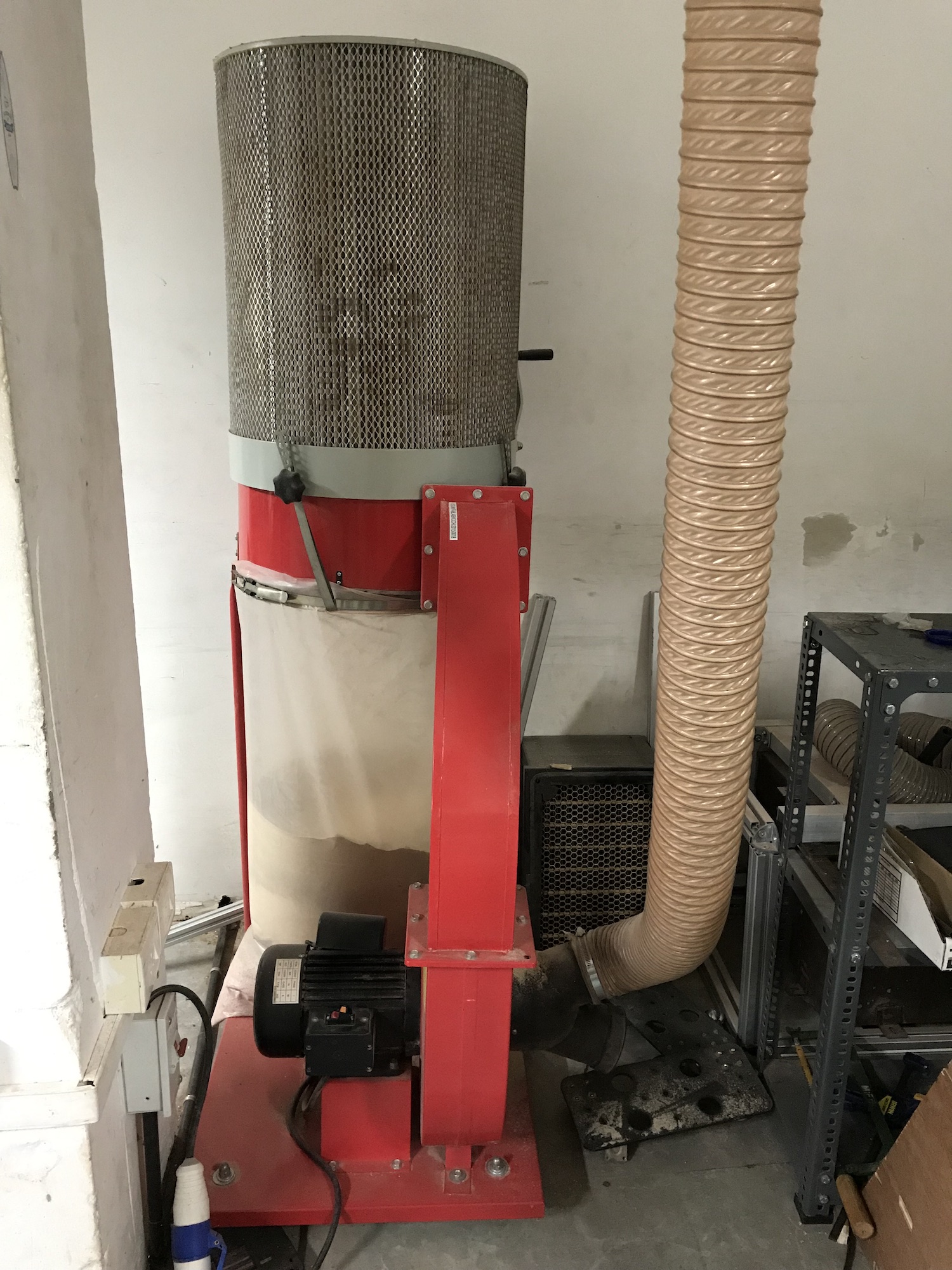
Since cnc machines are working close to human enviournment. We need to have proper arrangements to keep the place habitable to tha person also . Shopbot depends on these huge vaccum cleaner to suckout residues created during milling.
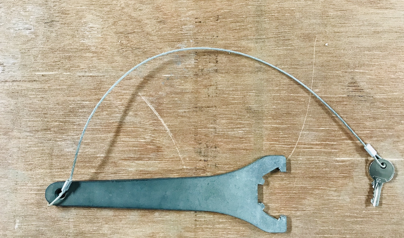
To prevent accidently turning on the spindle while we working on the chuck . The key for the spindle is attacked to the chuck releasing tool.
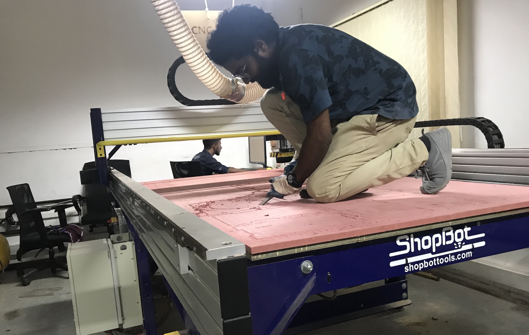
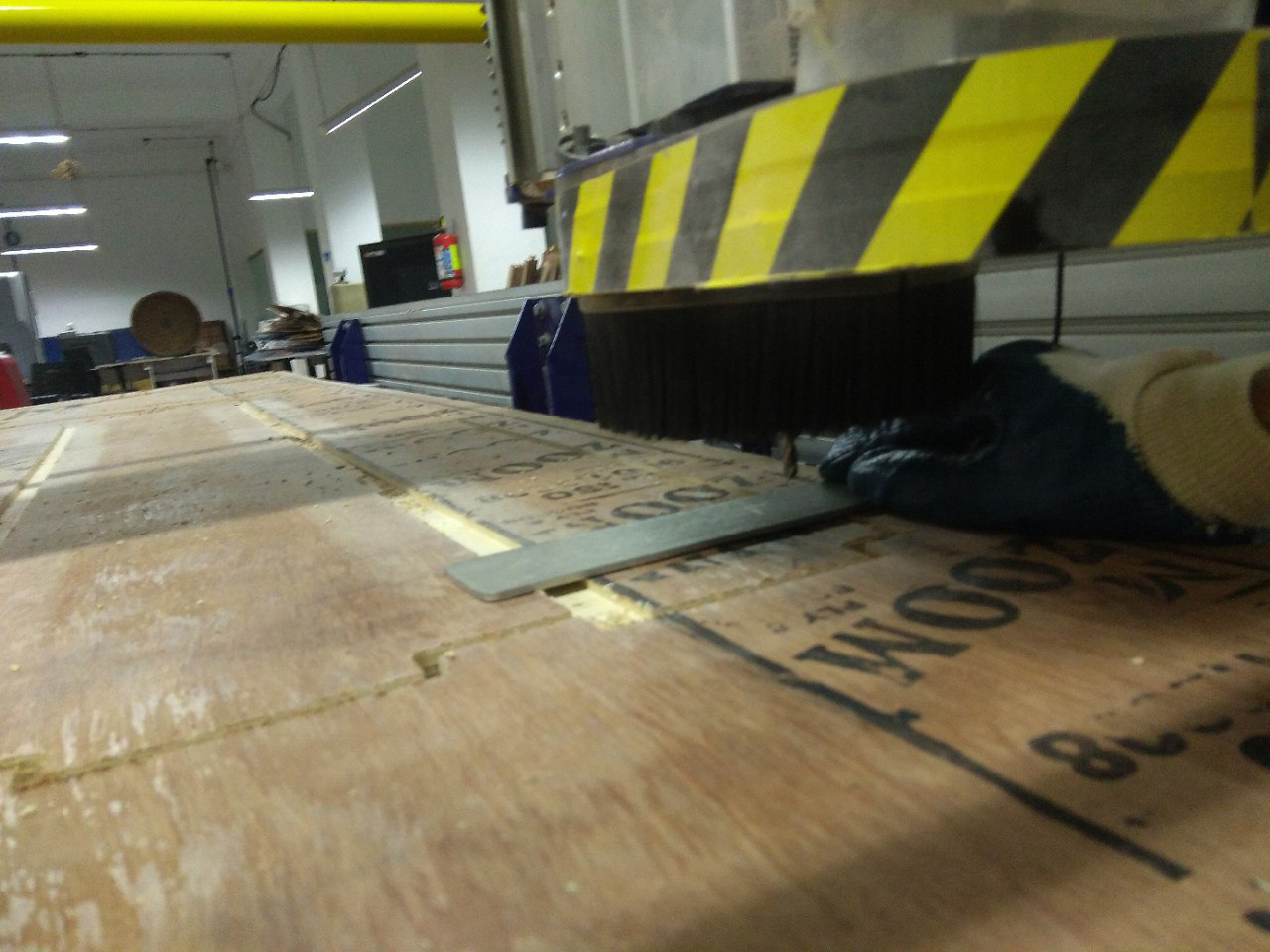
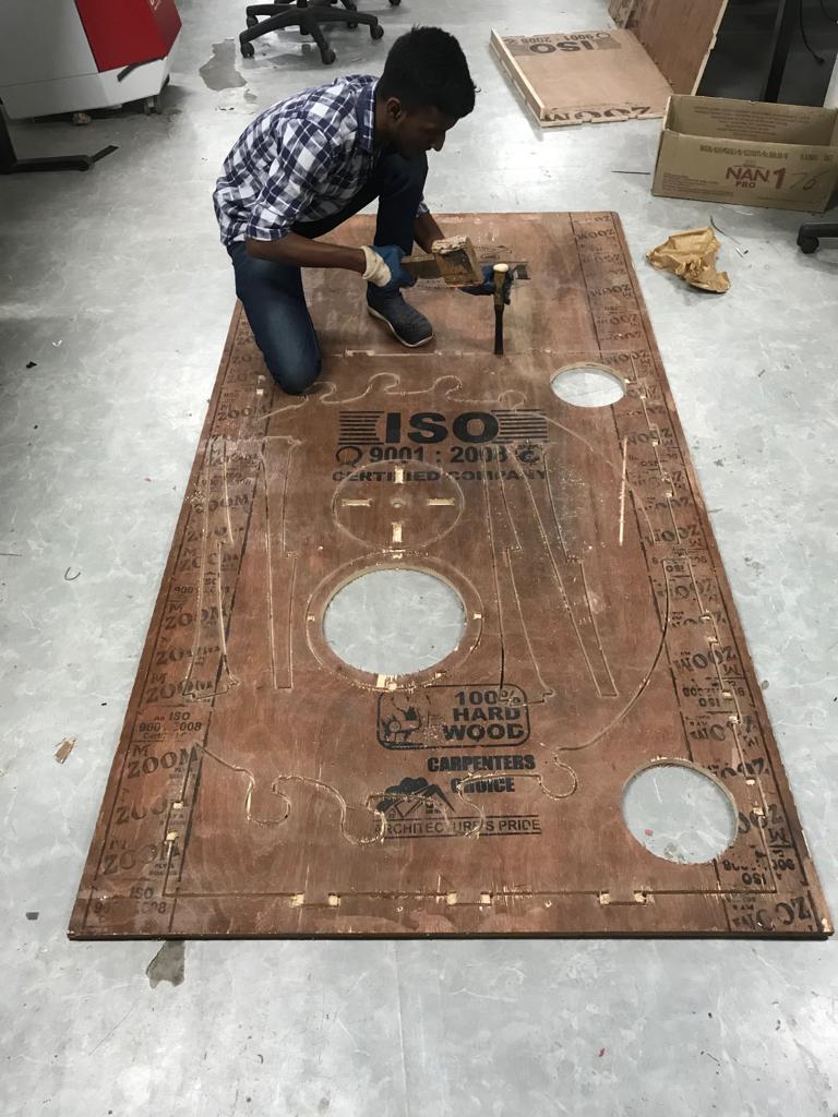
There are two 18mm plywoods stacked on the top of shopbot for the protection. It acts as a sacrificial layer and prevent the drill bit from hitting the metel structure of the machine. Due to the previous use of the machine the are so many irregular line on the the surface of the sacrificial layer. I manually removed the irregularities using the chisel.
Cutting The Design In Shobot CNC Milling Machine
Now I have to cutout the design in a 18-inch plywood using the Shobot. Turn on machine first, open the controller software for the Shobot called SHOBOT 3. I opened the X & Y position option in Shopbot 3 software to set the X&Y origin. To set the origin, first Open the X&Y positioning window in Shopbot 3.
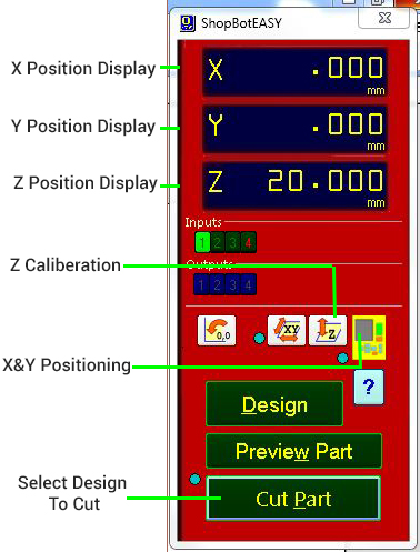
Then bring Tool head of the CNC machine by positioning the X & Y position using the D-PAD in the Window.
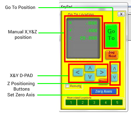
After bringing the Tool Head to desired position, click on ther Set Zero button. Then you will get a new window. check the X & Y options and then clik ZERO button. Now you successfully set the origin.
Next is to set the Z- axis. In order to do that, select the Z-positioning option Then You will get a message to place the Z Axis Caliberation Plate. Place the Caliberator plate in the material top surface and it should be below the toolhead. Then conect the aligator clip on the tool head & click Ok. the Z axis start to caliberate. Make sure your hands have a clear space from the bit. The Caliberation happens twice then click OK. We successfully caliberated the Z-axis.
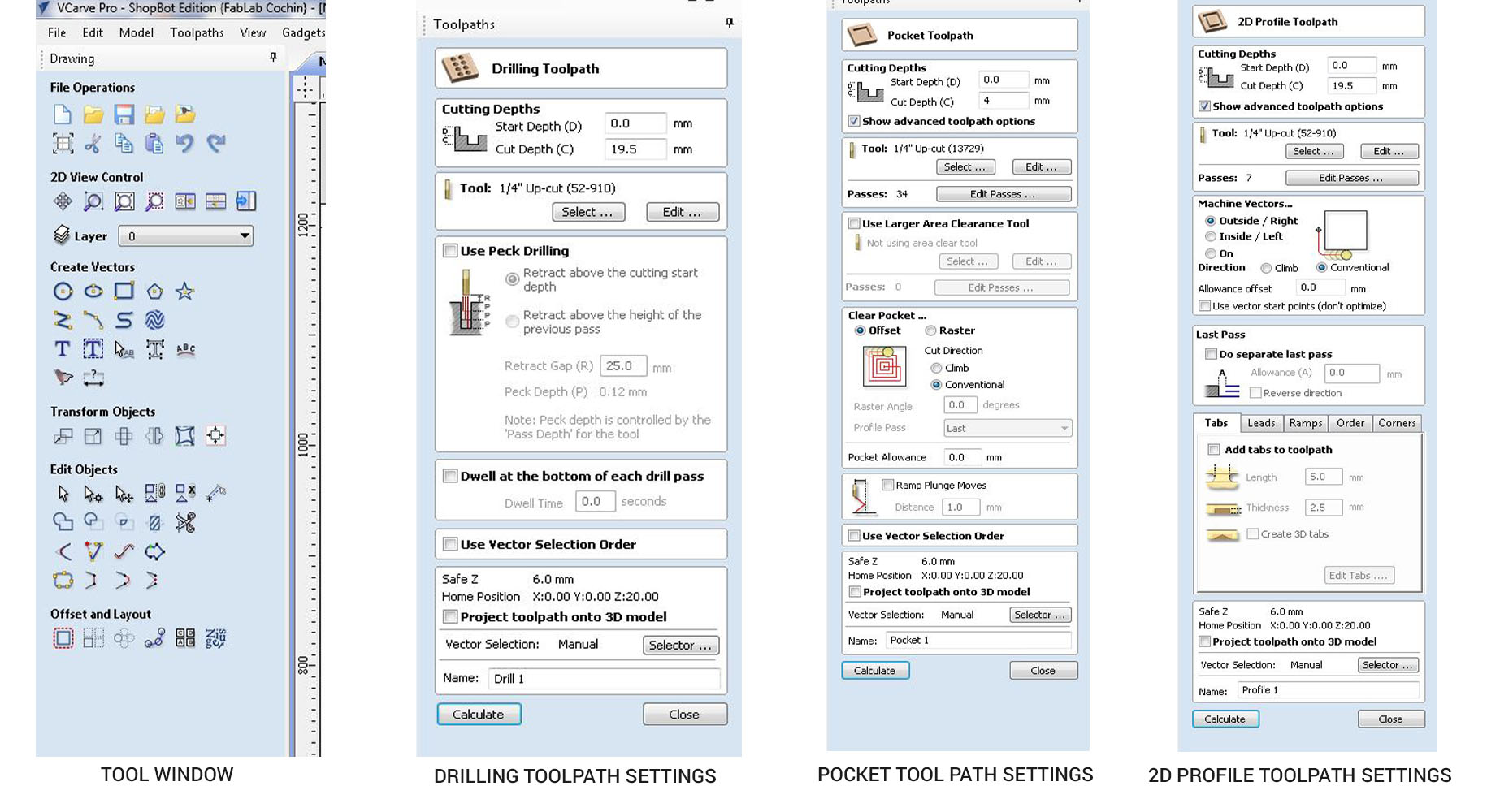
Now chose the Designfiles to the machine. We are using Vcarve software to do this. First import DXF files to the Vcarve Software then give the setting to cut out the Designs then save them all. the steps are briefly explained below.
Generating .SPB file Using Vcarve Pro
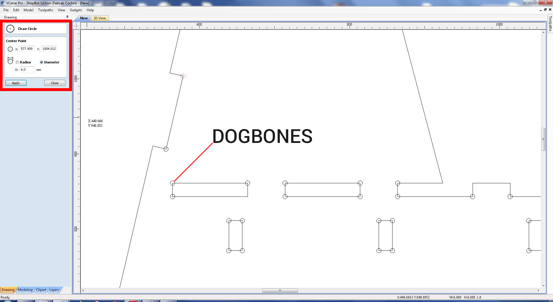
First open a new project with your bed size, mine was 8 X 4 Feet Size. I was using a 8 X 4 Feet Plywood. Then Drag and drop your DXF files into Vcarve Pro. Then after align your files as close enough, but not too close. Allign the, now we need to make the files that we need to cut and pockets. Follow the steps. After drag and drop the files then add DOGBONES in the corners of your pressfits. If you do not do this, the press fit won't fit well. Its important to do DOGBONES.
Then make the cutting settings. I used Profile cuttings, Drilling and pockets to complete my designs. I used profile cutting for cutting the outsides and used profile cutting with inside cutting option to make press fit holes in them. I used drill option to make the Dogbones in the corners of the press fits. Then used pockets with a 4mm depth for making the chanels in the workbench main sheet to give the supports. After saving them in appropriate names.
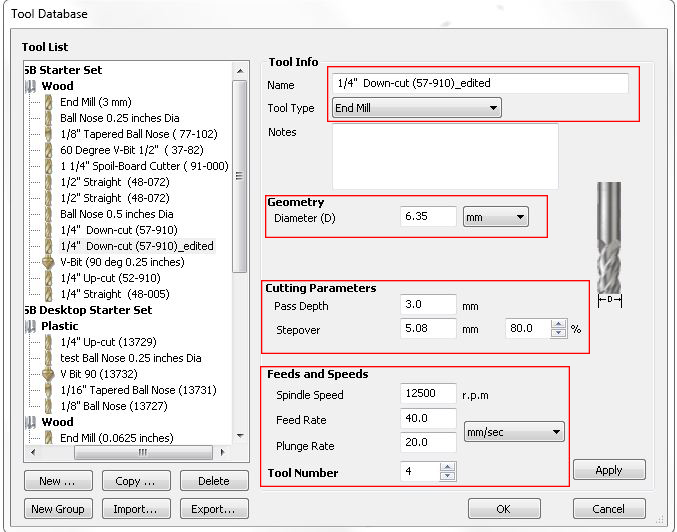
Feed rate and RPM
I used a 1/4(6.35mm) Downcut and end mill to machine all the parts using shopbot. I set the pass depth to 3mm. Then set the spindle speed to the maximum 12500RPM and the feed rate to 40.mm per second.
Now we are set, open the Shopbot software and then open the cut file by selecting the Cut button. Then focus on the machine, activate the interlock key to activate the spindle. Then click on the Start button, you will get pop message to turn on the spindle by pressing the start button on the ESTOP button control. The spindle starts rotating, you are good to go. Click start buton in the software. The machine starts to do the job. But youl'd ready to press the ESTOP button if anything went wrong. Sometimes there is high chances to break the bit or some injuries. Always recommend to to do CNC machining with a partner. After cutting out all the parts I need to assemble them . Here is a snapshot when i assempling the parts.
I took this timelapse video using my phone on the tripod.
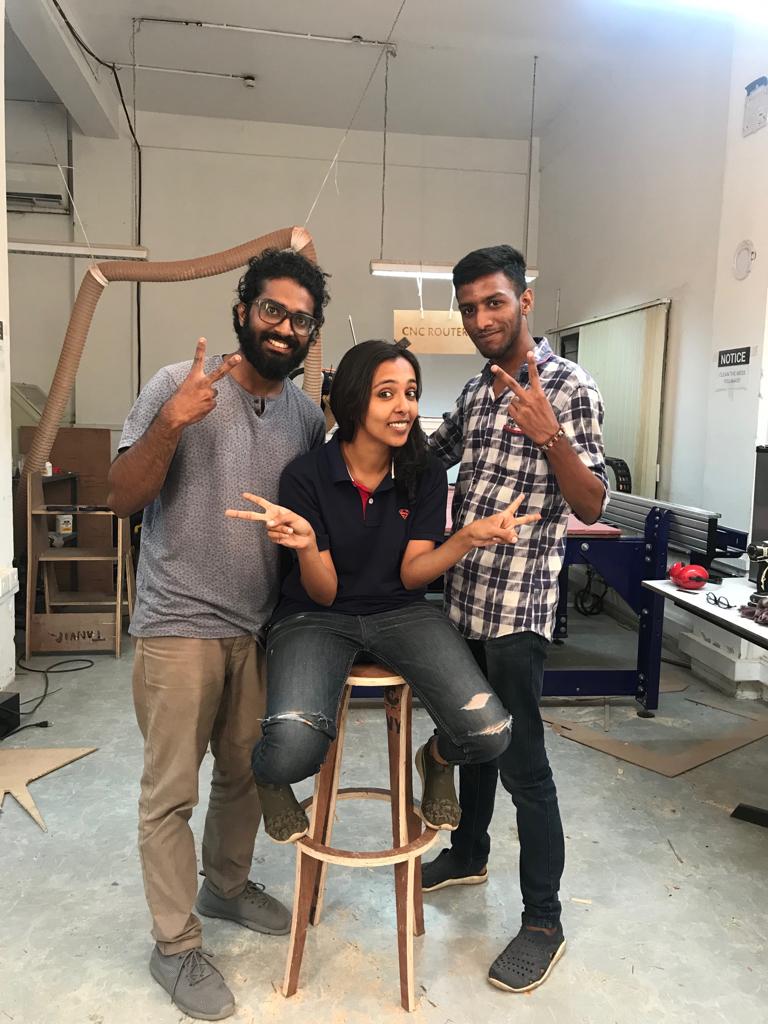
My friend Jofin helped removing removing parts and assemling them.
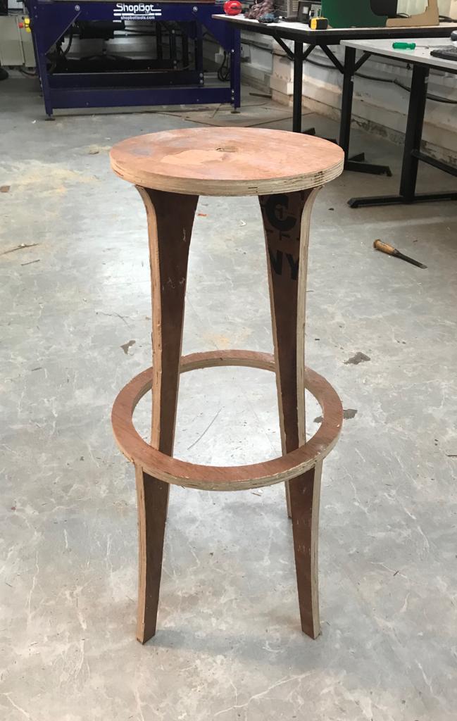
This the final image of the stool.
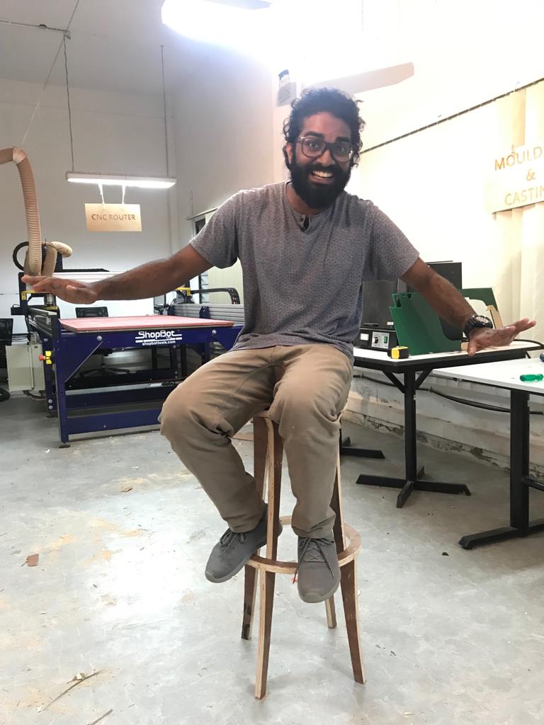
Hero shot...!!
Since I made the legs very thin, it is not strong enough for a heavy person.
Download the design file here