From testing the arch, the cap falling which helped in designing the back board and then overall design of the project I was ready to get started in making my final game.
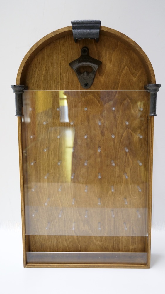
The first stage was to see how I was going to get the neopixels to attach to the back board with the dowel infront of it and then the side glow as close to the neopixels so it would light up correctly. I knew the distance of the dowel but haven't done the joining the whole of them up.
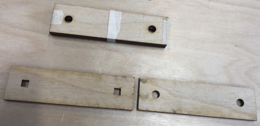
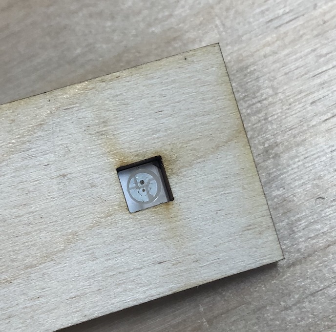
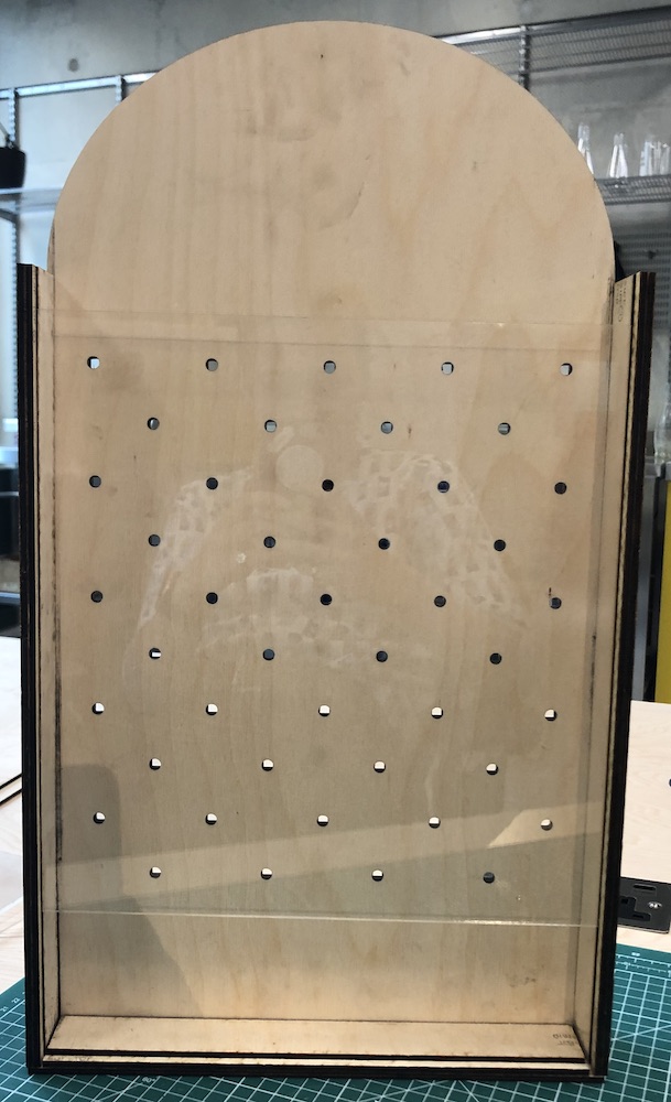
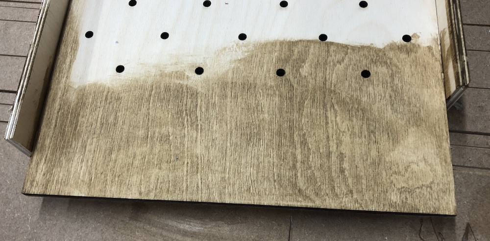
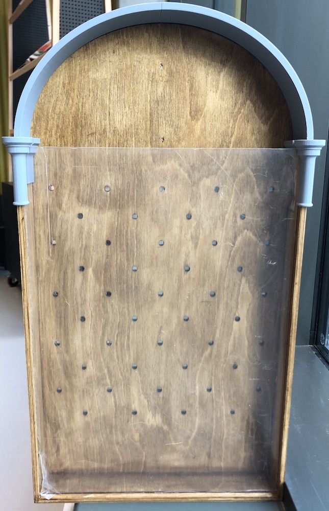
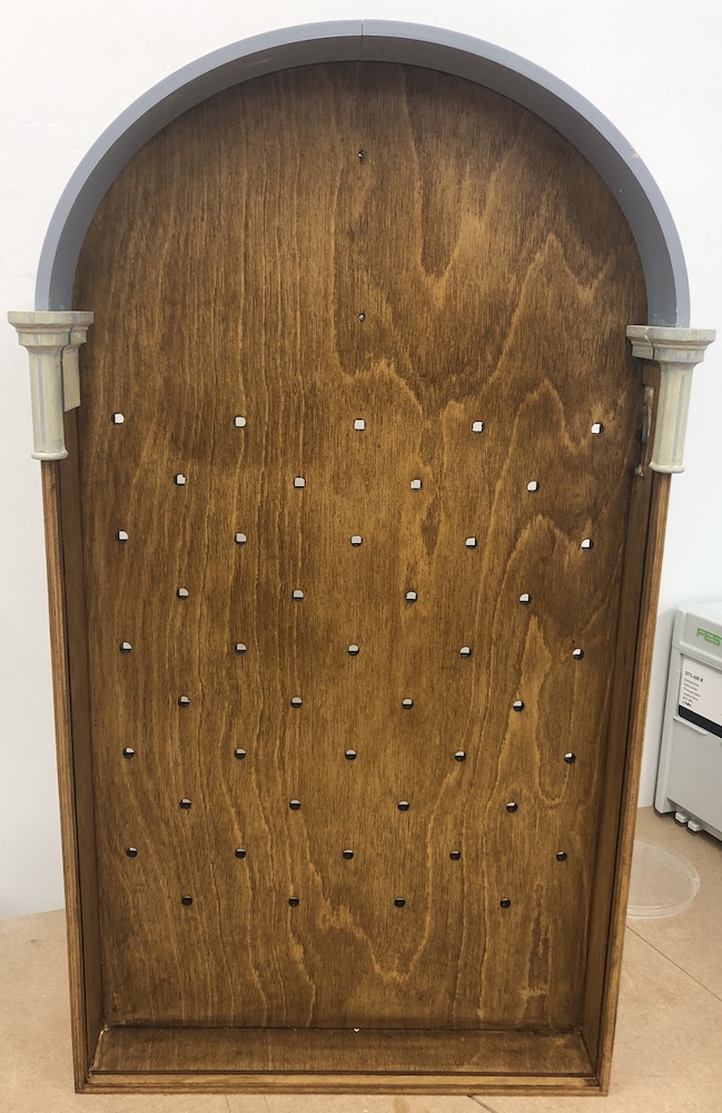
As I was laser cutting the whole of the back board and frame this meant I could do the wholes in there, I knew the dowels would need round wholes at the front to allow for them to hold in and then the neopixels needed something in the back. As they were square and where small I tried to make square wholes in the back board and then glued the two together. This meant that the dowel was as close to the neopixel as possible but also meant that the whole thing could slot together easily at the back without extra bulk.
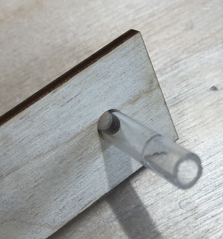
It worked well the neopixels fitted snug, I would have to glue them to secure them and then the dowel would just slot in as you can see below.
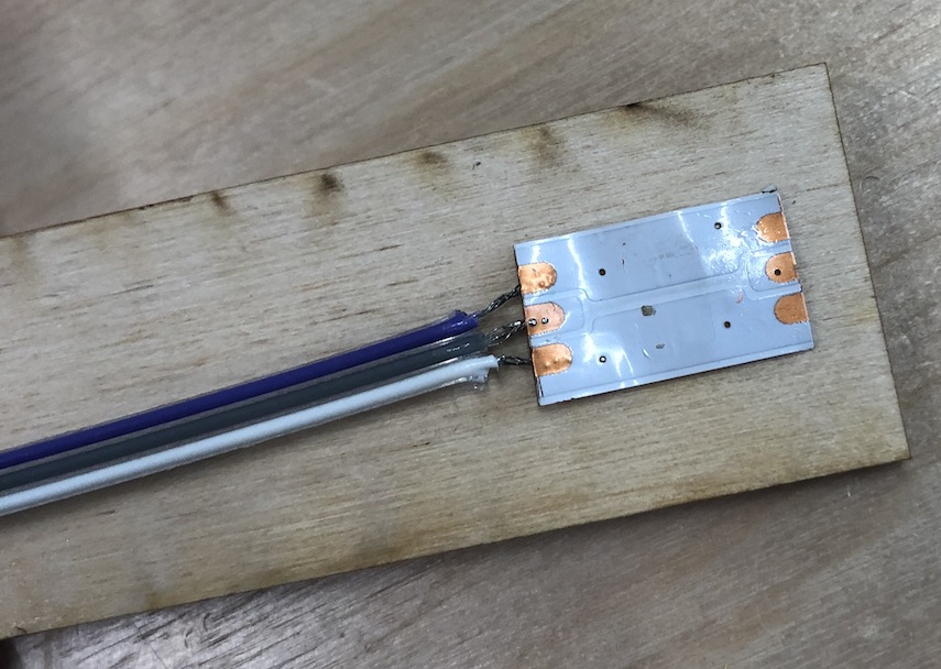
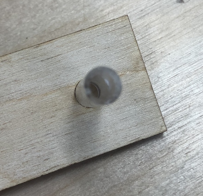
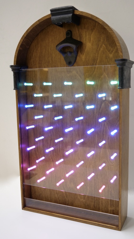
I also tested this with the neopixels light up behind to makesure this would all work well together in the future. The acrylic would also help the side glow to stay inside the tubing rather than having to glue it all together.
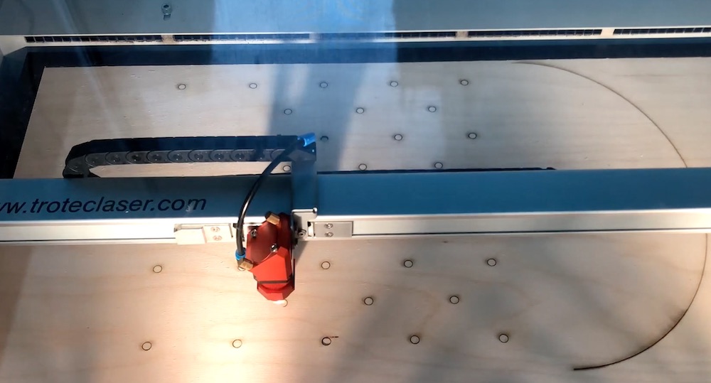
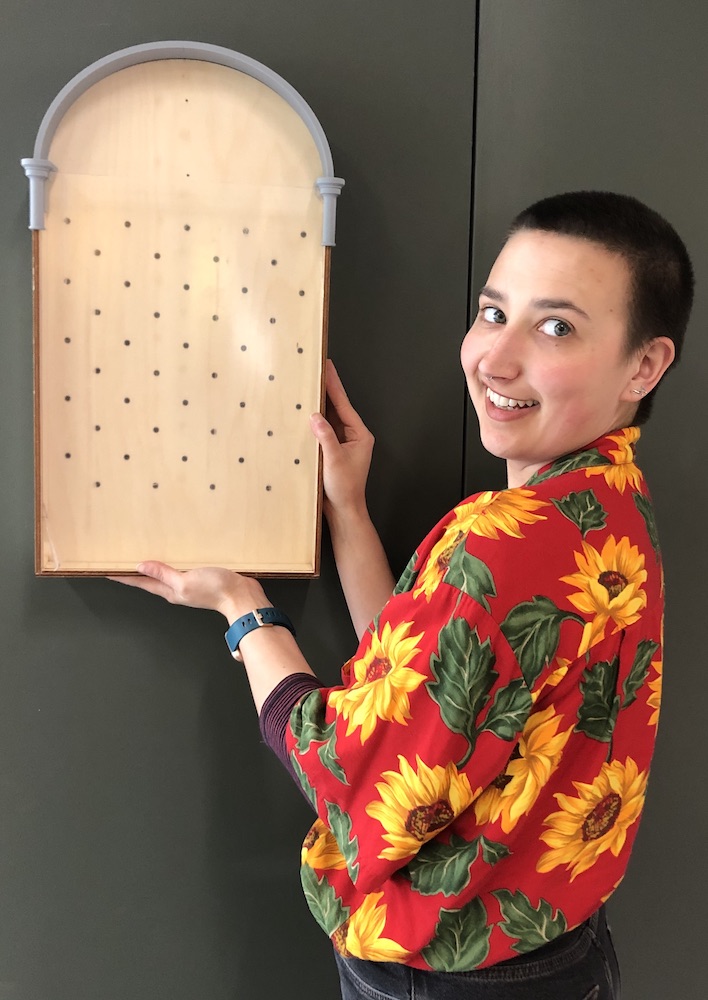
I got the fusion files and placed them into inkscape to then cut them out on our laser cutter. This was very exciting to watch as the final game had started, I then glued the whole back boards together to become one, avoiding to get any glue in the wholes otherwise this would ruin the neopixels and dowel filling in perfectly into the cut wholes.
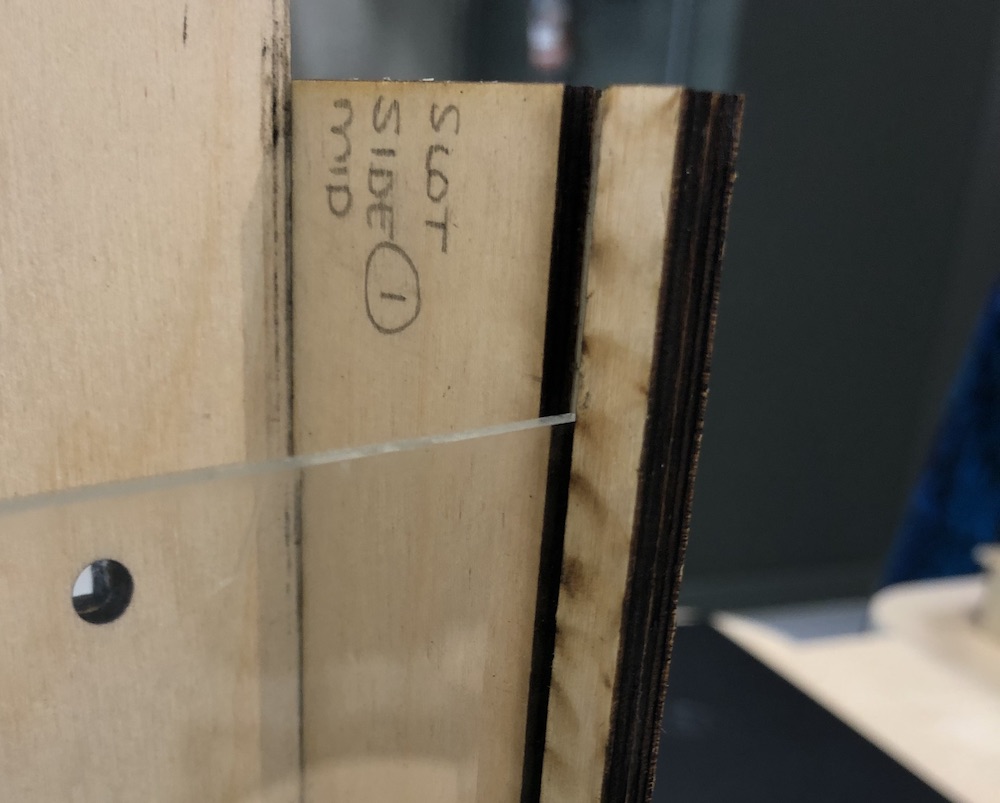
I then cut the frame of the game which was more complicated than I thought as there was a lot of parts and it was difficult to remember what went with what so I named them as they came out to not forget. The two side pieces were the same but the bottom piece was a little more complicated. I did have to cut this out twice as the first time I had made it a little too smalle therefore the side frame bits angled in which would not work with the acrylic in place.
I used super glue and wood glue to makesure it would stick quickly (the super glue only a small amount) and then the wood glue to get the best stick for the future. This was something I have learnt from watching people do fiddly wood glueing in the past.
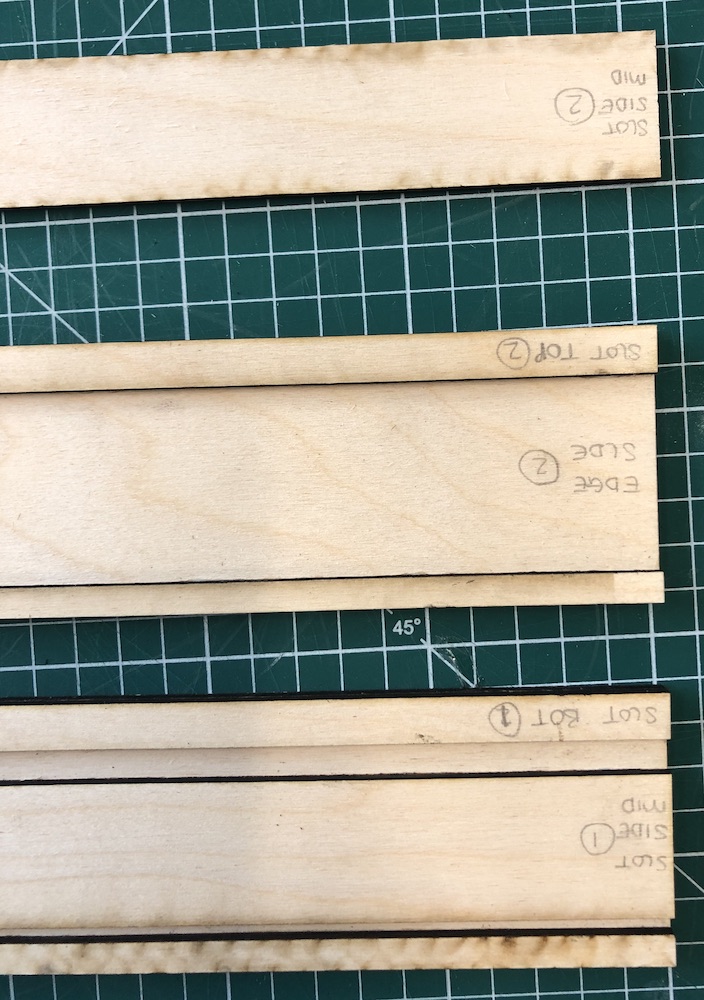
To makesure when I was glueing everything was lining up correctly I would place the acrylic sheet and teh back board into the slots on the side frame to double check when I was glueing it was lining up correctly.
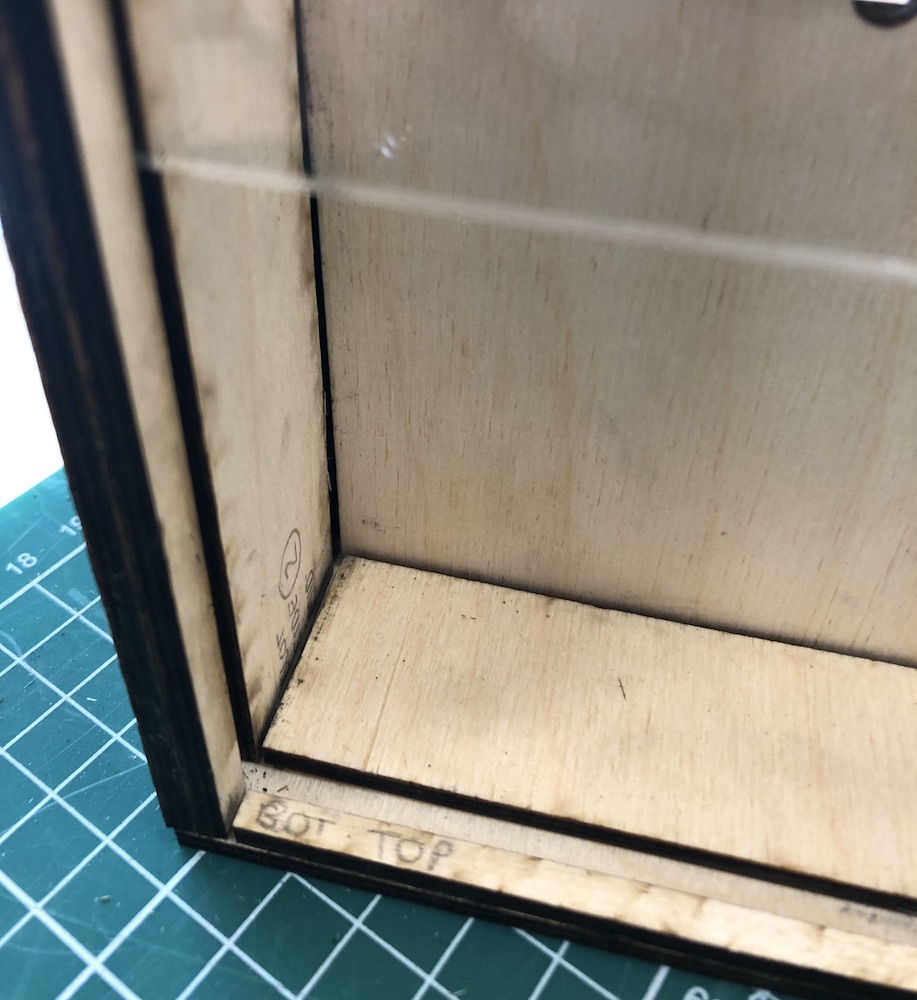
I then placed it all together to makesure it worked and then I realised I needed to make a whole for the sensor to go in the side so I cut out a new frame and did the same glueing technique. I also made the side pieces longer so that the back had more space for the board and electricals to hold it in place.
Overall it is looking good and can't wait to get this stained for the wood effect I am going for.
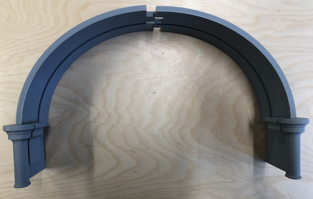
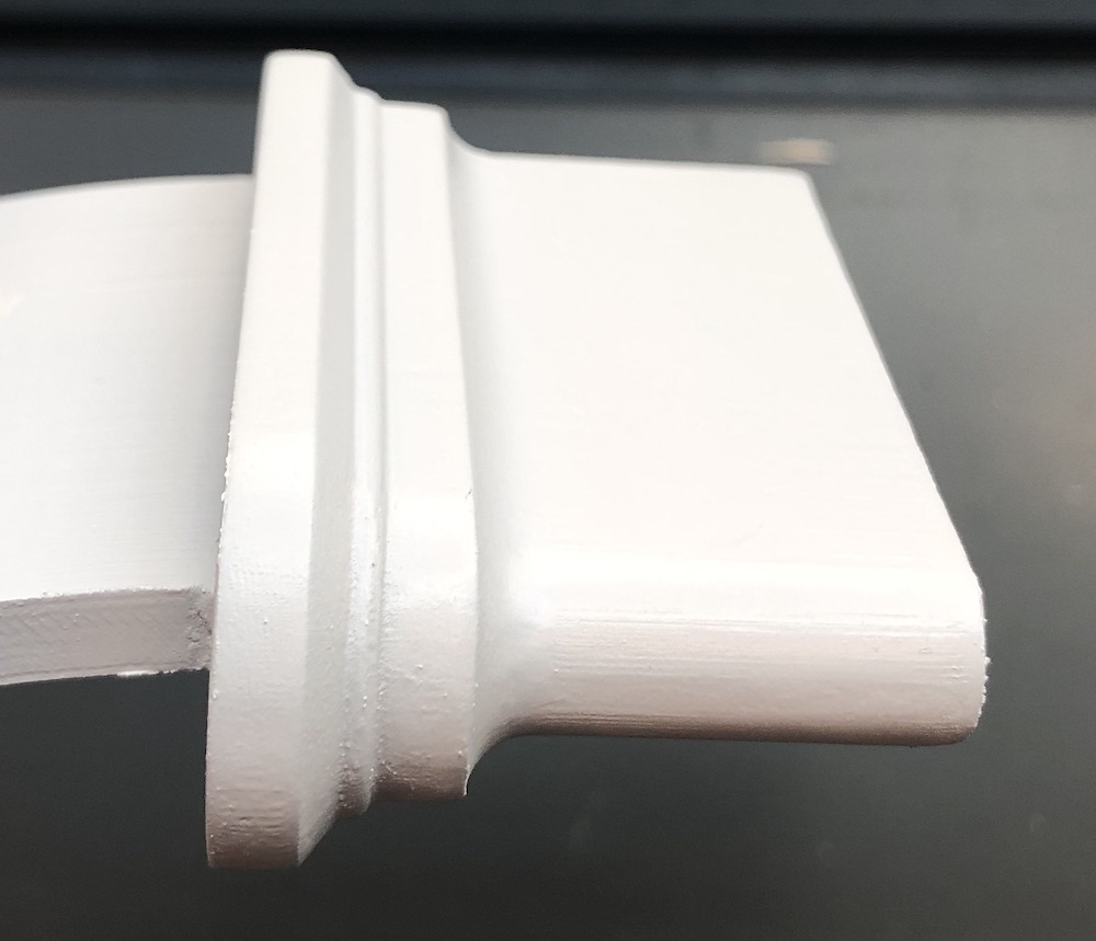
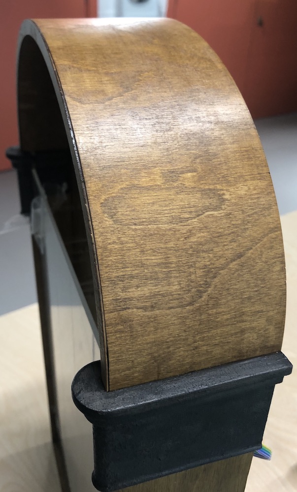
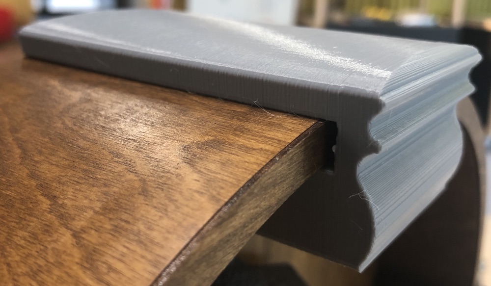
So from testing the arch in previous weeks and learning that 3d printing it with moulding that would then hold the 0.8 mm plywood this is the final print for these arches plus moulding. I added the supports that prusa slicer gave you as this worked well on a trial print and from a print before where I hadn't I really struggled to get my own made supports out.
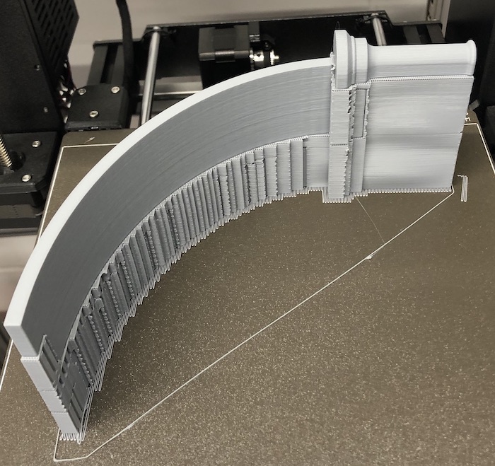
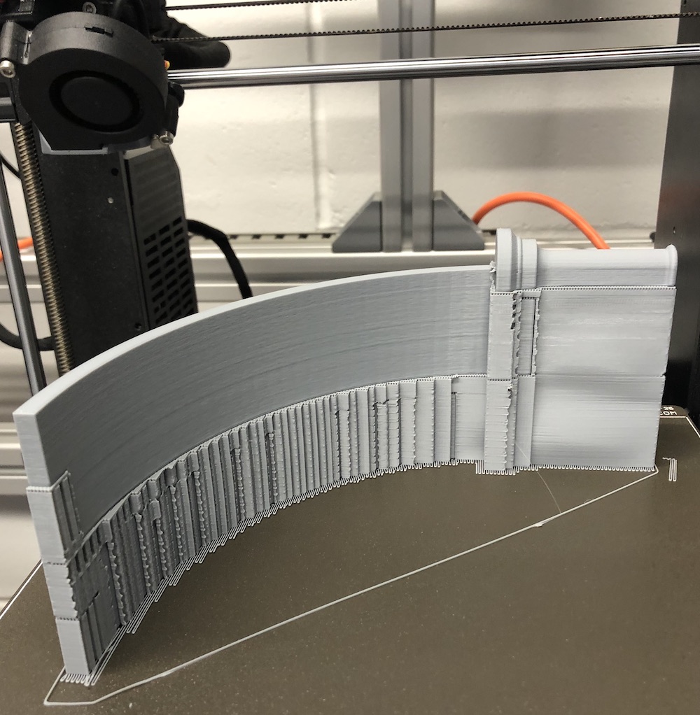
As you can see the final outcome as amazing, I couldn't have asked for it to come out better! the filament I used worked very well and the way that it slotted not the main body was great. I also added the little extra beading on the bottom of the arch which made the difference when it come to finishing a design and making it authemtic.
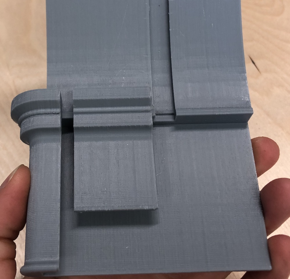
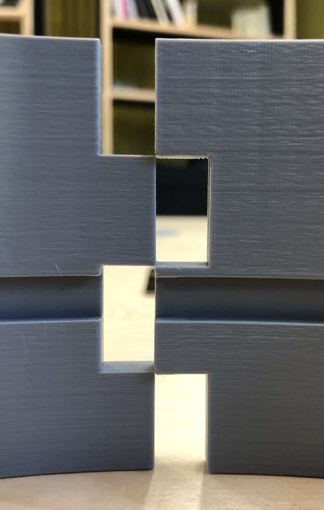
I then lined up the joining fingers and glued them together with super glue, I had tested this before on another piece of PLA and it held well and as this wasn't getting any force I knew it would be fine.
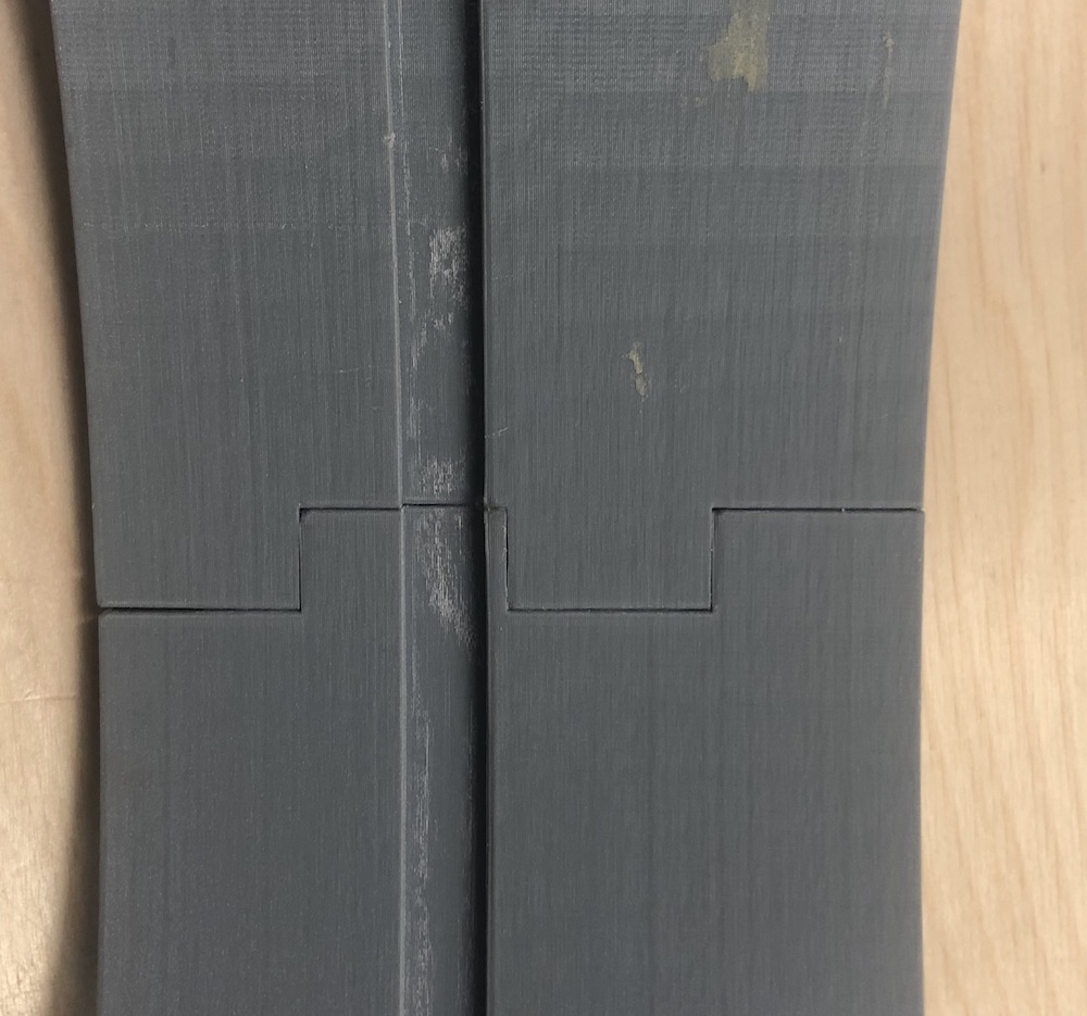
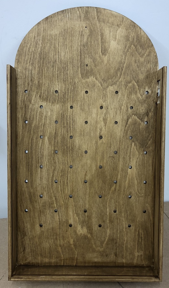
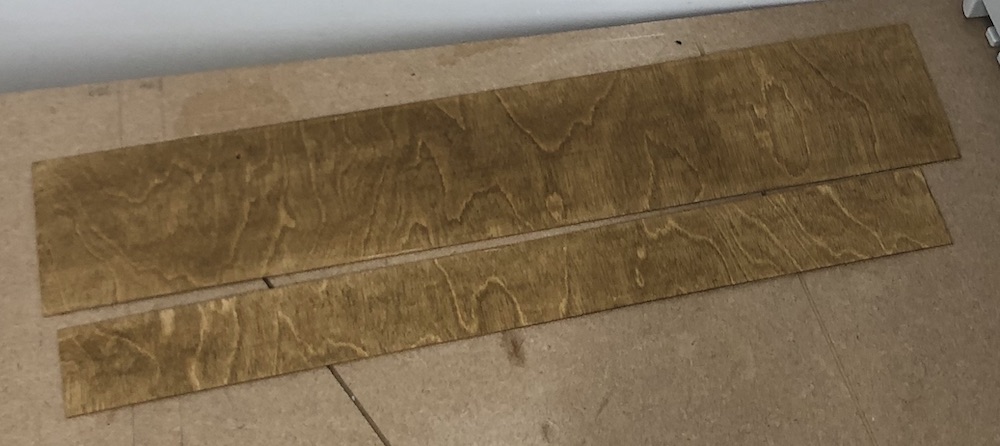
I then sanded down the main body, glued it together ready for staining. This is what it looked like before I stained it as Andrew said this would be a good idea to see the difference and I must say it is amazing what some wood stain can do to laser cut ply!
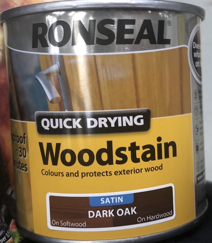
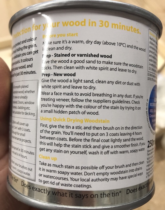
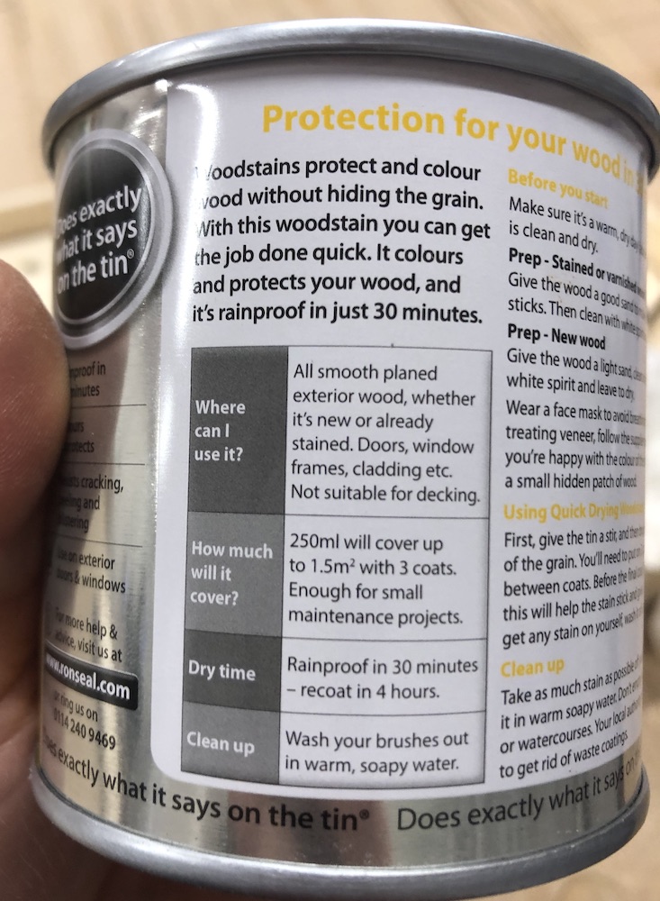
The stain that I brought was from BnQ Andrew had recommended the same brand but hadn't had much luck with his stain for some reason. I chose a satin finish as I didn't want to vanish it after and then I made sure to read the back of the packaging before I used it. On the back it said to use a brush but from speaking to people and knowing Andrew had used a cloth to apply his I did the same.
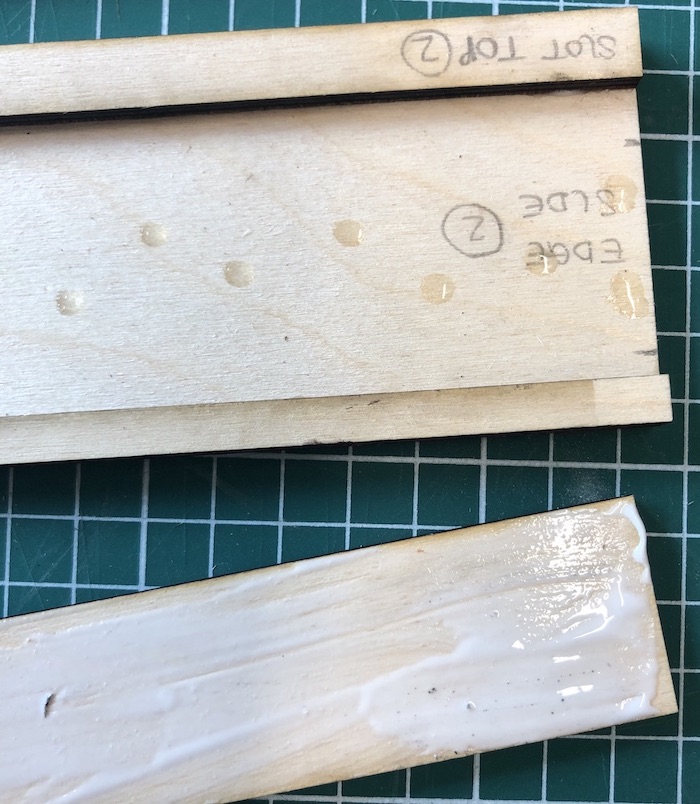
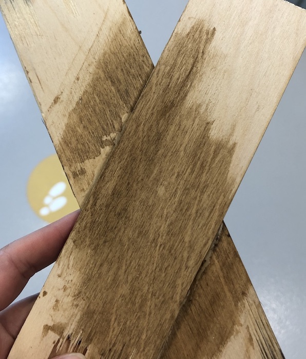
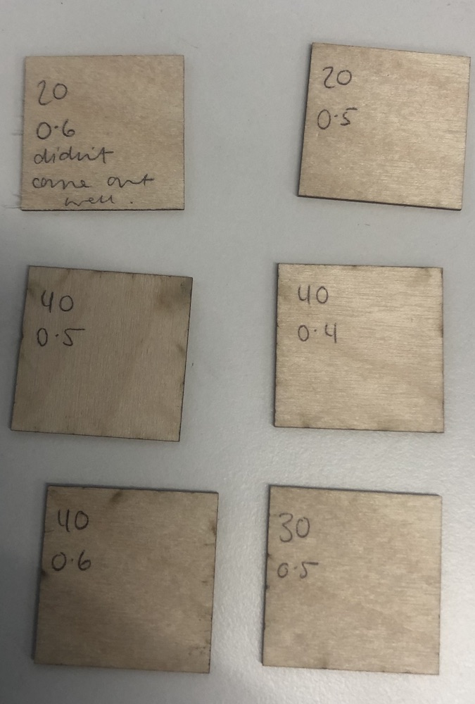
I started by doing a practice stain on my protoype and then on a scrap bit of wood with wood glue on to see how the stain did if it came into contact with it. As you can see it did not do well, the image on the left there is a mark where the stain did not take to the wood and this was where the wood glue was not cleaned up properly. On the right hand side photo this is showing the stages of coats I put on the wood to get the oat affect I was looking for. I did around 4 coats and this was the shade that I wanted, any darker it didn't work as against the bottle opener it didn't work well together.
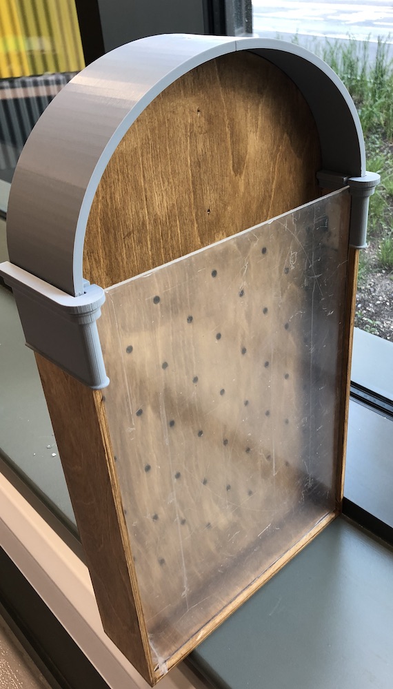
After doing this I placed my gloves on, mixed teh stain and applied 4 coats with a cloth being careful not to get it in the gaps and trying to keep it even around the whole body and frame. All together the whole game is look very good withe arch attached as well it is looking even better, you would not know it was laser cut ply which makes me very happy with this outcome of the stain.
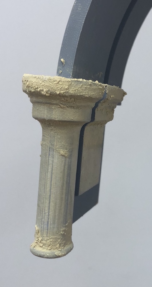
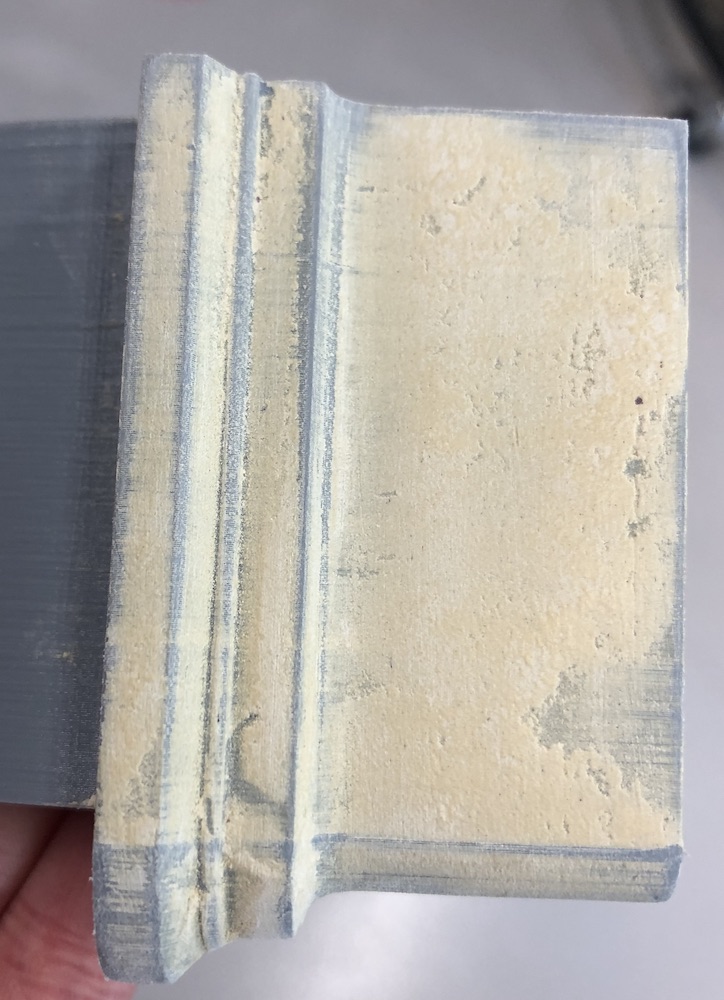
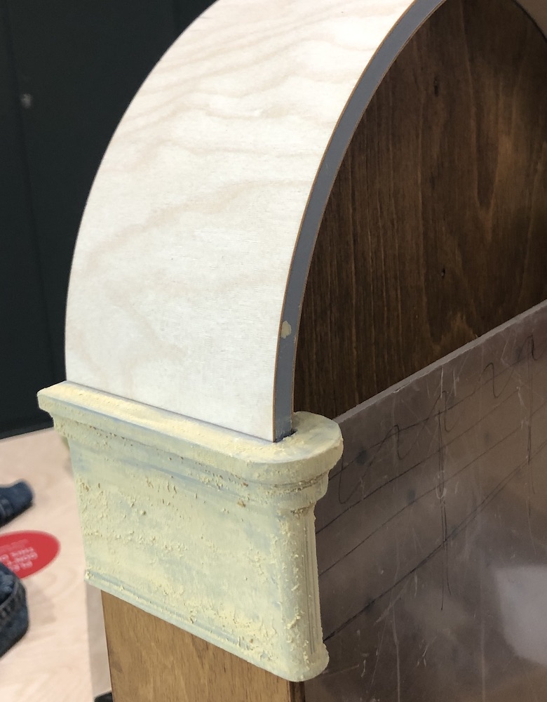
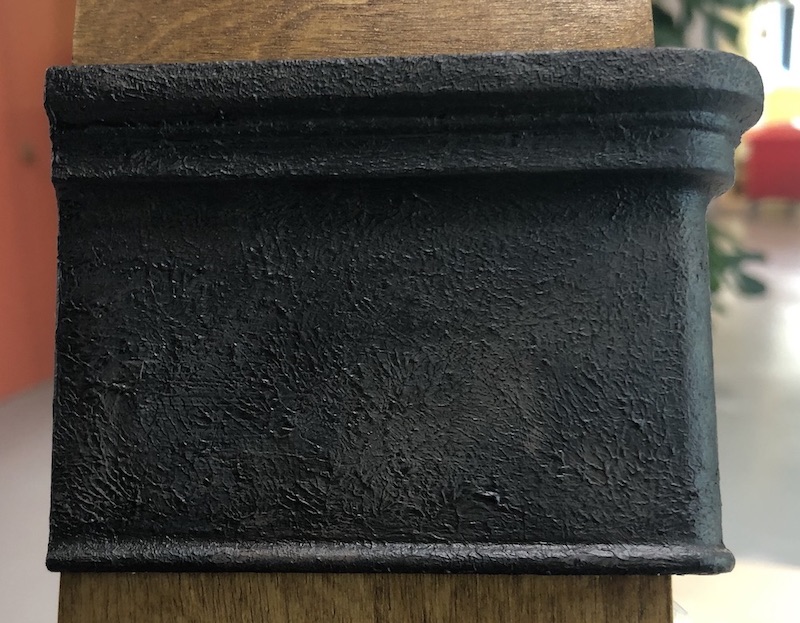
To get the smooth texture on my moulding I used a natural coloured food filler using thin coats on the moulding in our air vented room as it was a very strong smell. I wore glues to not get it on my hands and made sure I was mixing it correctly so I got the right consistency.
This worked well I did around 3 coats of this wood filler before I sprayed on the primer as the primer brings out every issue you have in your peice. I ended up painting mine as you will see in a textured finish so the smoothness was needing to be 100% perfect.
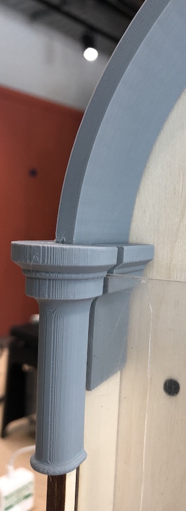
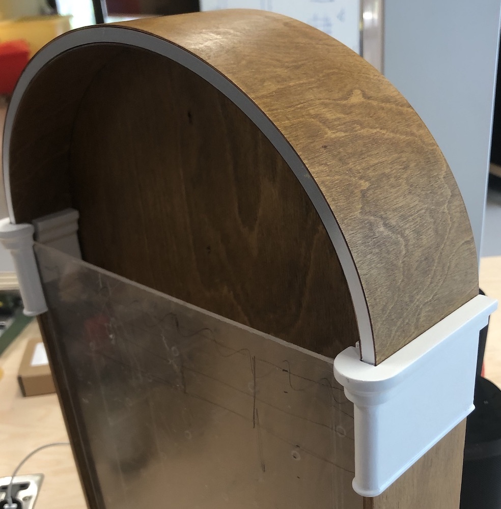
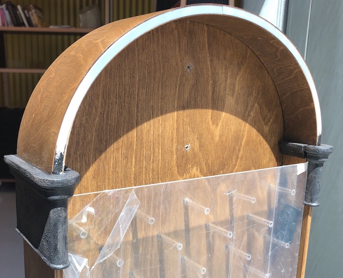
With the arch and the moulding almost complete I placed it on the main body to see how it was going to look everytime as it was very satifying seeing it coming together.
Now that I was dong the moulding between coats I was getting the arch 0.8 mm ply sorted. I had tested it before to makesure it fitted before I started doing the wood filler and it did fit well. I was making sure to avoid the gap between the moulding and the arch to not get wood filler in otherwise the 0.8 mm ply wouldnt fit. The overall look was coming together nicely.
I made sure to do some test cuts on the laser cutter to check that the wood wasn't being burnt as I was cutting it. In the end the power 20 and speedy 0.5 worked the best so this is what I used to cut my plywood. It fitted very nicely onto the arch and overall I was very placed with the outcome it gave, I cut an outside piece as you can see here but also an inside piece for under the arhc which isn't quite visible in these images.
I then sanded and stained the 0.8 mm plywood with 4 coats just like the main body, sanding lightly between each coat to keep it smooth.
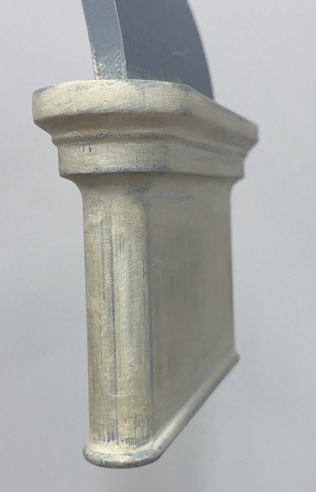
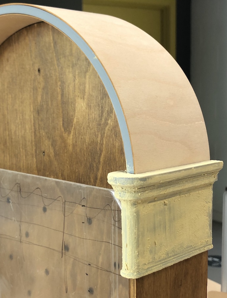
Once completing all the layers of filler and sanding it down I sprayed it with primer as you can see here, then placed the plywood in place to check the spray painted hadn't gotten stuck in any of the gaps. It came out very nicely and was looking forward to seeing it all come together!
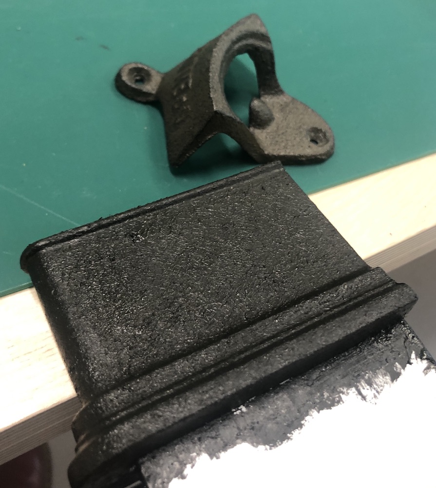
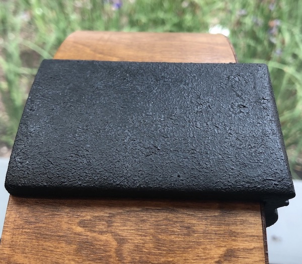
I then started on painting the arch, I did a base coat of black with the texture as close to the bottle opener as I could get. I was trying to get a rusted look to begin with which was not working at all.
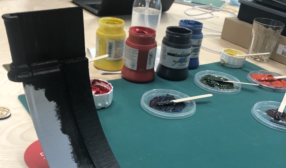
So I started again with the black and looked up how to get the colours I was looking for, overall I was needing a light brown and a grey/ brown as this would match the bottle opener. My aim was to avoid making a whole new colour as this would add too much because I already had a lot of colours, texture and materials.
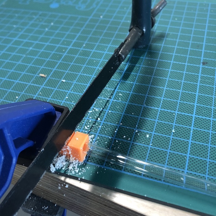
To cut the cowel I 3d printed a jig so that all the acrylic would be the same size, this didn't work very well and I had to sand all 45 pieces down to the correct size but overall this was a good idea I should have ust used a better jig in the end.
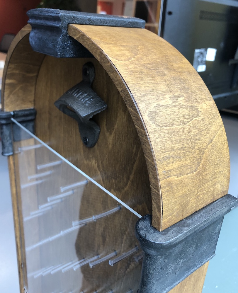
To make the front arch I started by going into fusion and getting the front plain I had from my arch drawing. I added a few more mm on each side to take into concideration the 0.8 mm plywood added to both edges and then cut it on the laser cutter in cardboard first. This did work every well and it made me realise I needed to make it slightly bigger for the piece.
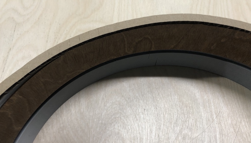
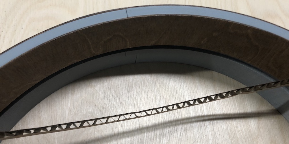
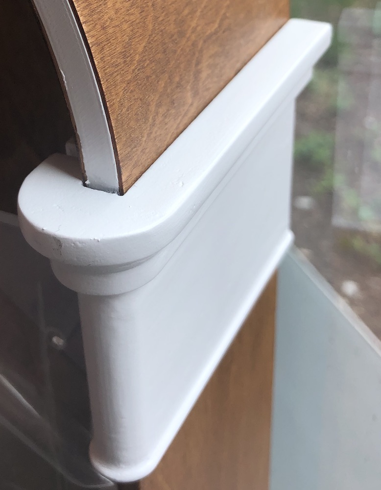
I then cut it out of the plywood, stained it and trimmed it down a little bit more ont he bottom edges that met the moulding as the gap I was going to place it into was rather messy and full with wood filler and spray paint (forgot to check this area at the beginning). I glue it together with some super glue and in the end I think it does look very good. It does look like one piece of wood from the side, from the front the edge of the laser cut plywood frame slightly changes the illustion but unless you know what to look for I think it has come out very very well!
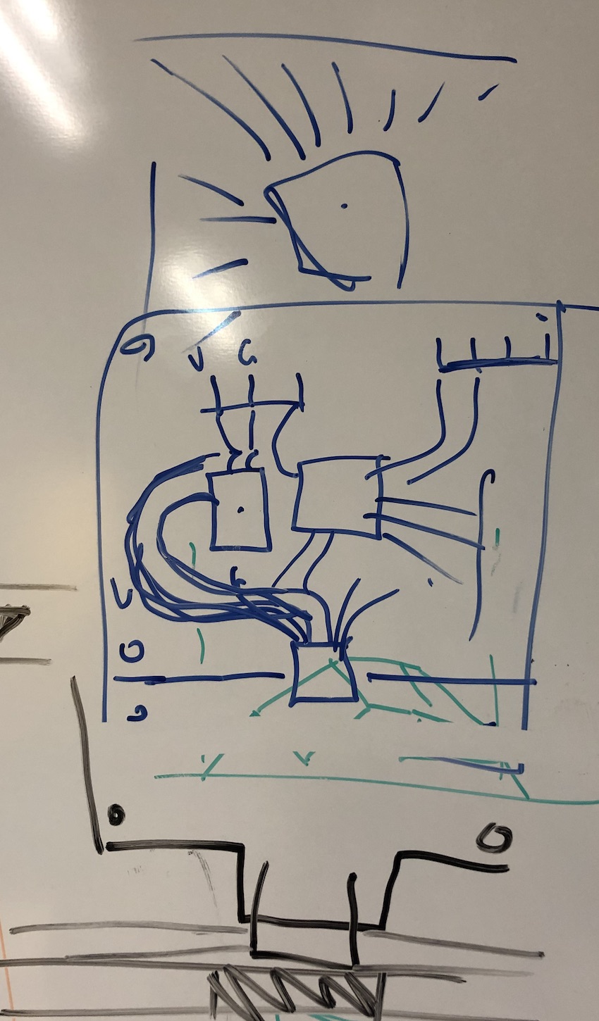
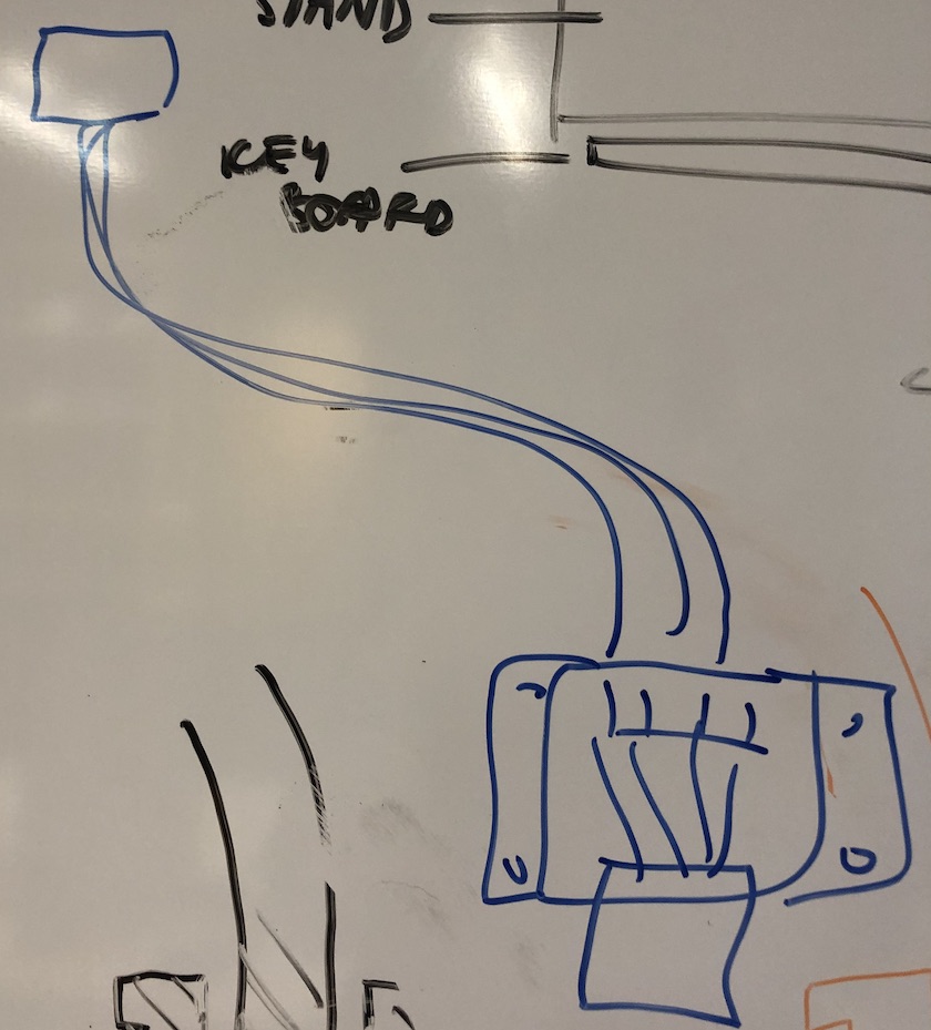
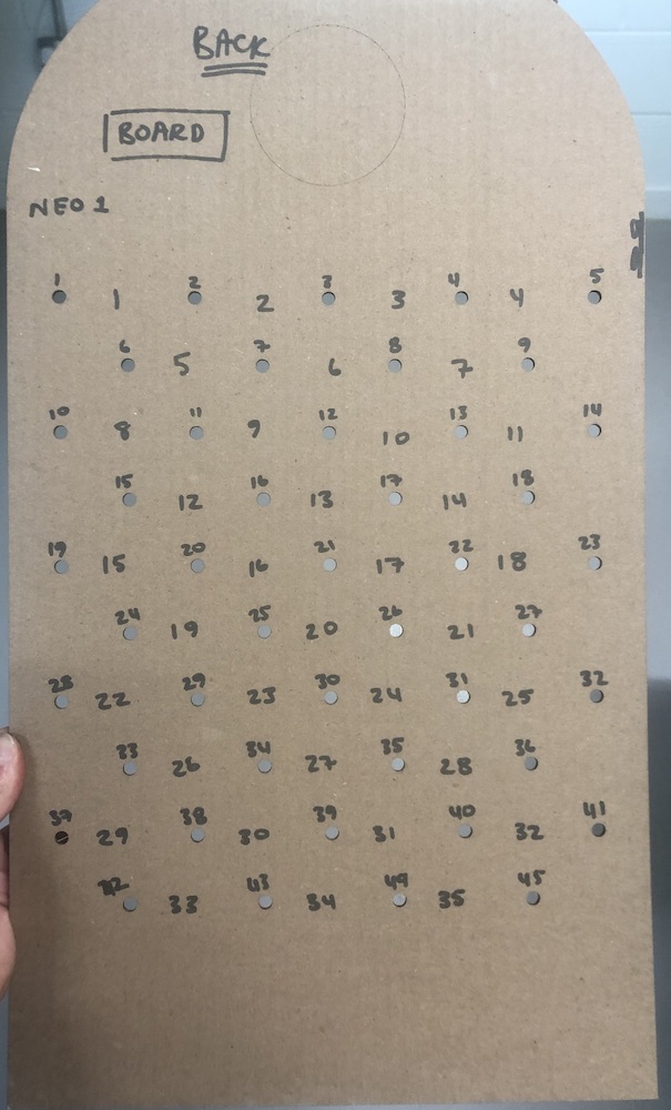
I was talking to Andrew about my board aand how it was going to sit on the back of my piece as well as what I need how it should come together and where everything should sit.
Knowing that the wires shouldn't be tangled and that the sensor is coming from the left side and then the neopixels could come from the right as this would be better than the top. The board layout would look like how I have drawn in on the back of my board.
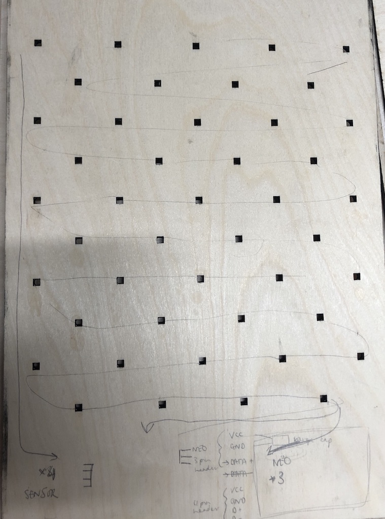
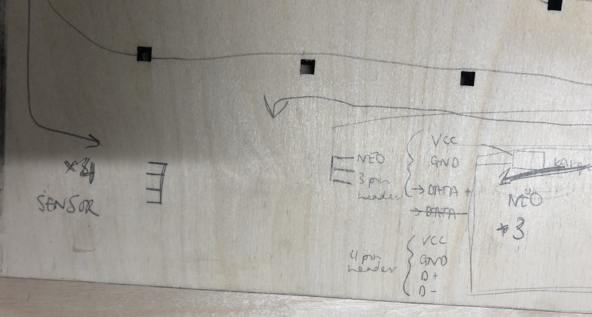
Andrew mentioned about my large capasitor and how it need to be between the neopixel pinouts and the chips pinouts I have chosen. Then about the sensor pinouts and where they need to sit compared to see how they are going to lie on my board on the back of my game.
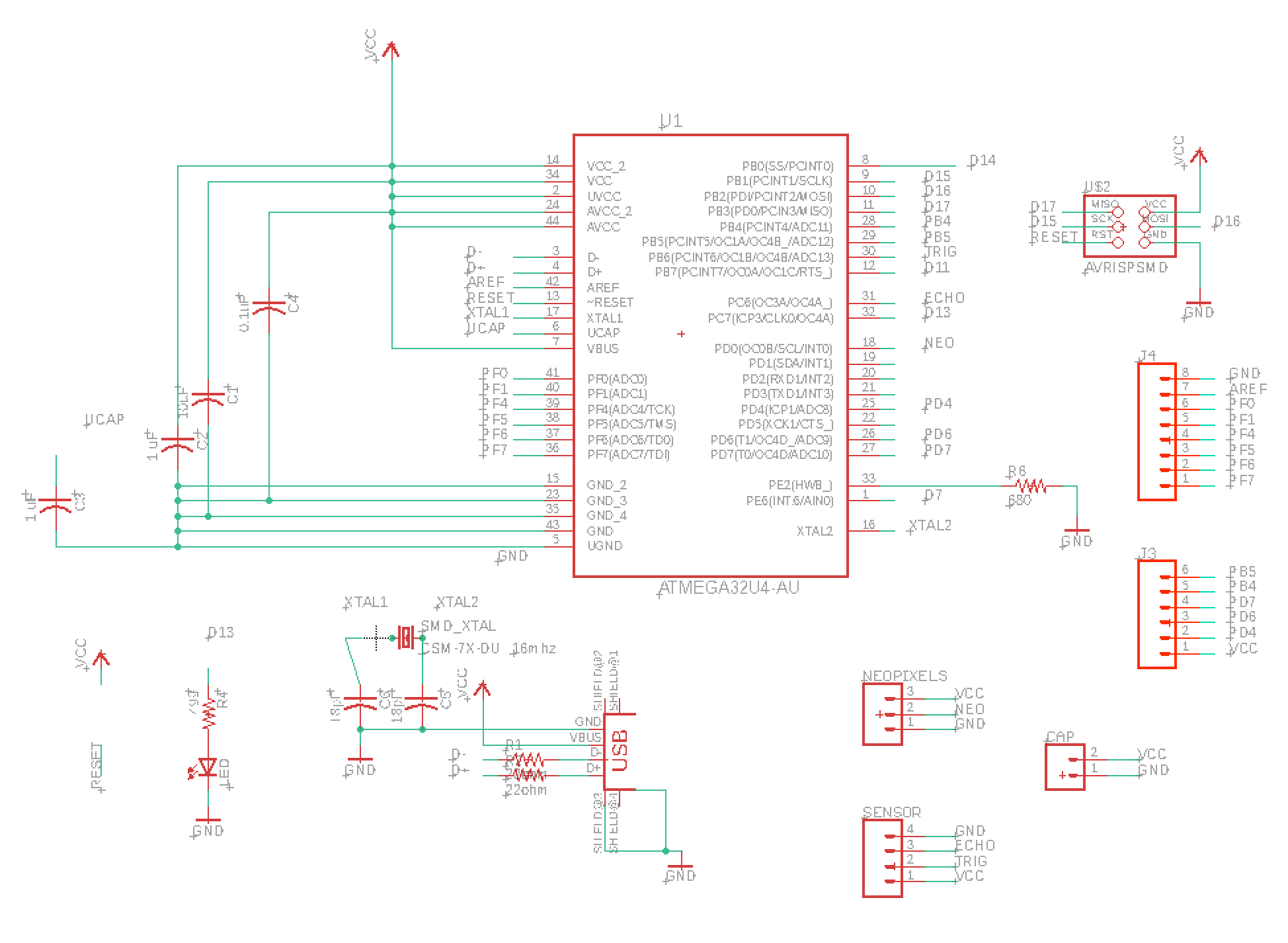
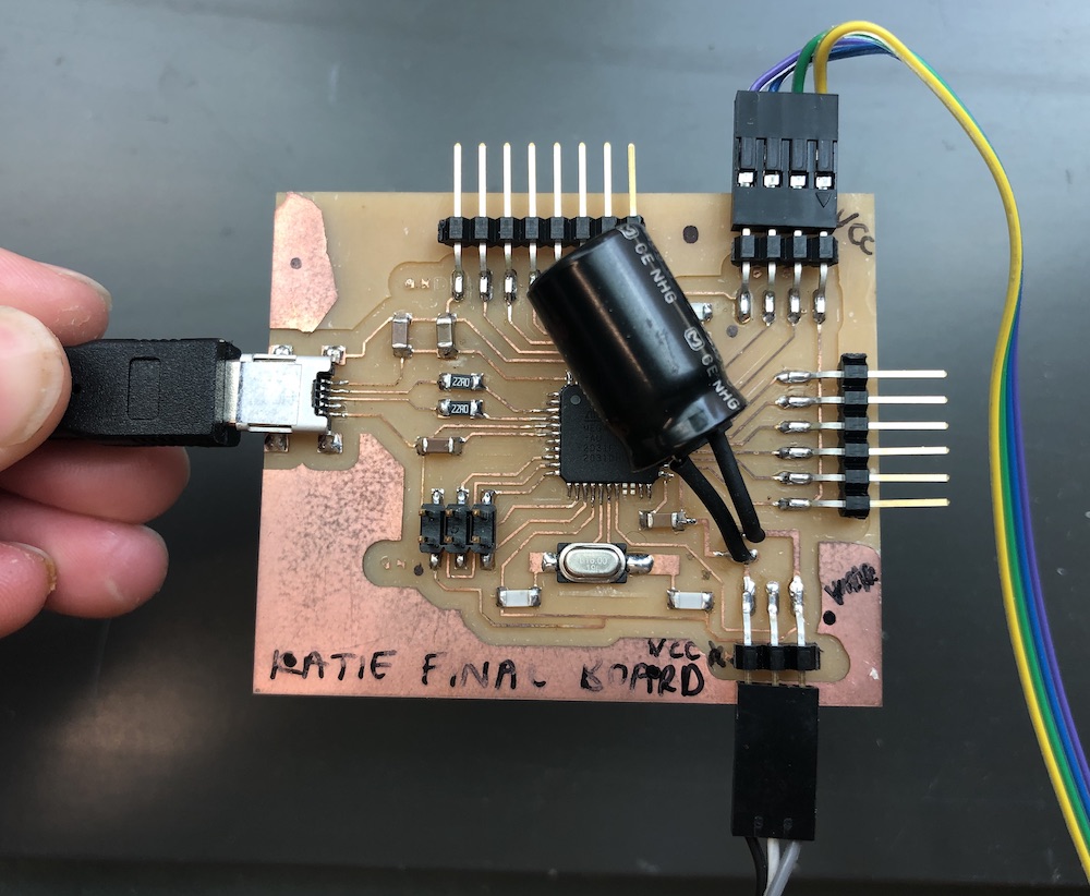
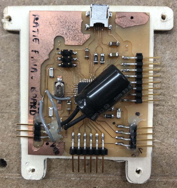
I used Luiz board as a template for my board and you can see the developement of this in week 14: embedded networking and communications. I added my four pin header to the top of the board for my sensor and the 3 pin header to the bottom of my board for the neopixels and the large capacitor for the neopixels as well. It was quite easy to bring everything that I needed into his schematic which was good also trying to makesure I wasn't moving anything of this as I was doing it. I also brought out the rest of the pins on the board just in case I might need them in the future.
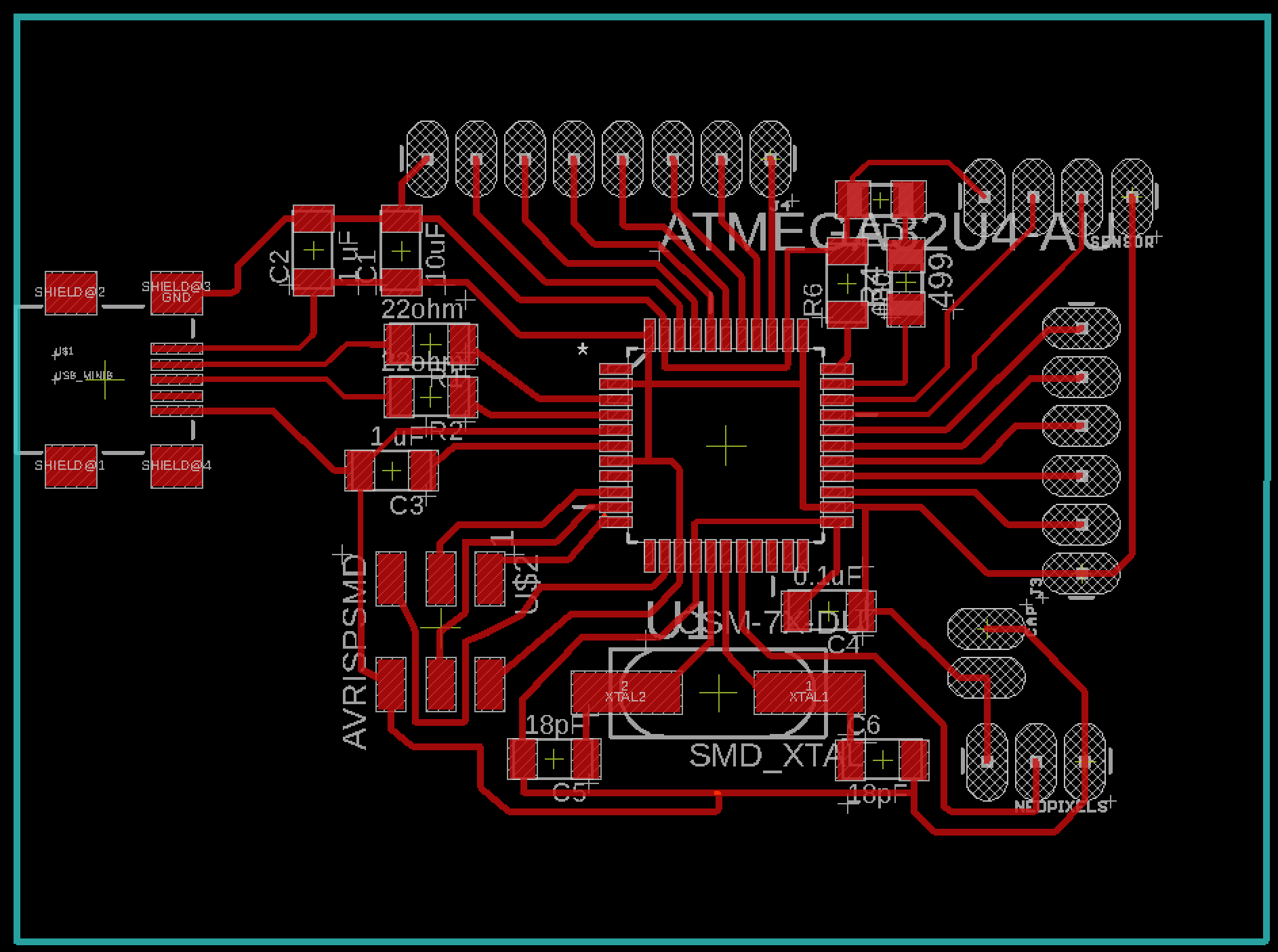
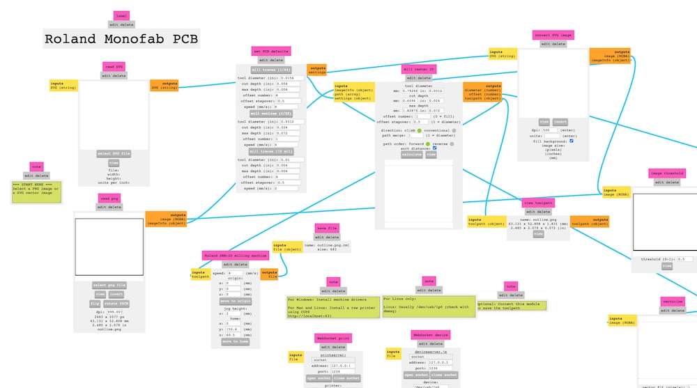
I then exported them and placed them in mods to be programmed into the correct format for cutting on our milling machine.
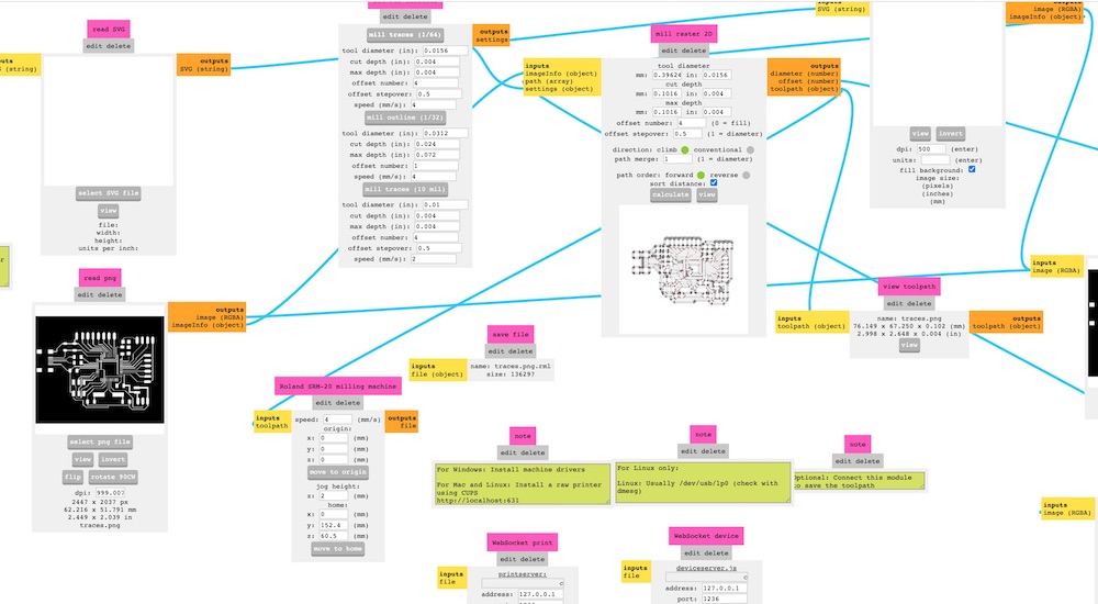
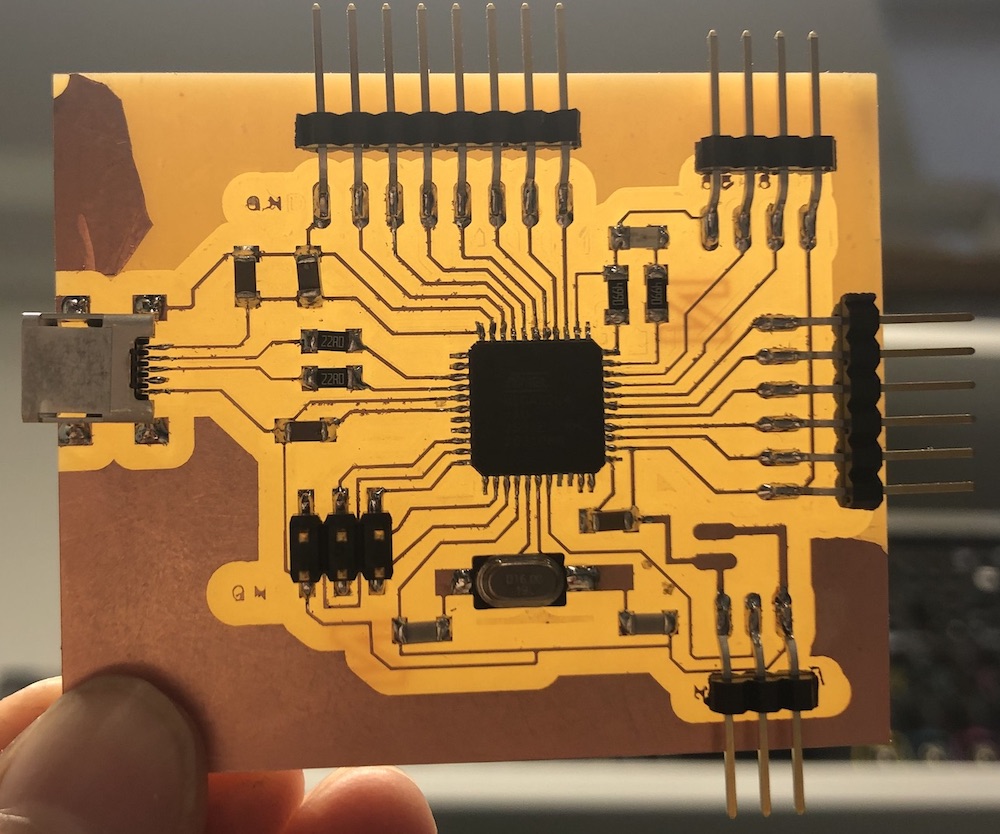
It came out great with the traces coming out well and the outline lining up with the board correctly as I had to make the whole things bigger to fit my parts on correctly.
I stuffed it and then without the large capacitor as I didn't want to ad dit before it had 100% worked as this would give me issue with checking the board because it is so big.
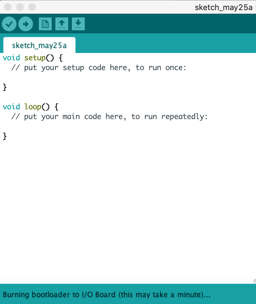
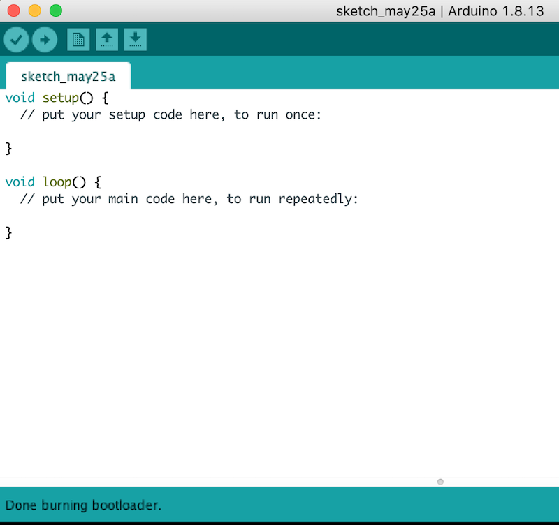
I then moved onto burning the bootloader onto the board and if you go back to my week15 I had quite a few issues with getting it to work but in teh end by following someone else tutorial they should that I needed to use the 'Arduino Micro' rather than the 'Arduino Leonardo'.
So the bootloader worked which was great after I did all those things as suggested by someone on reddit who was having the same issues. yay!!
I then added a blink sketch to see if this would work and it did!!
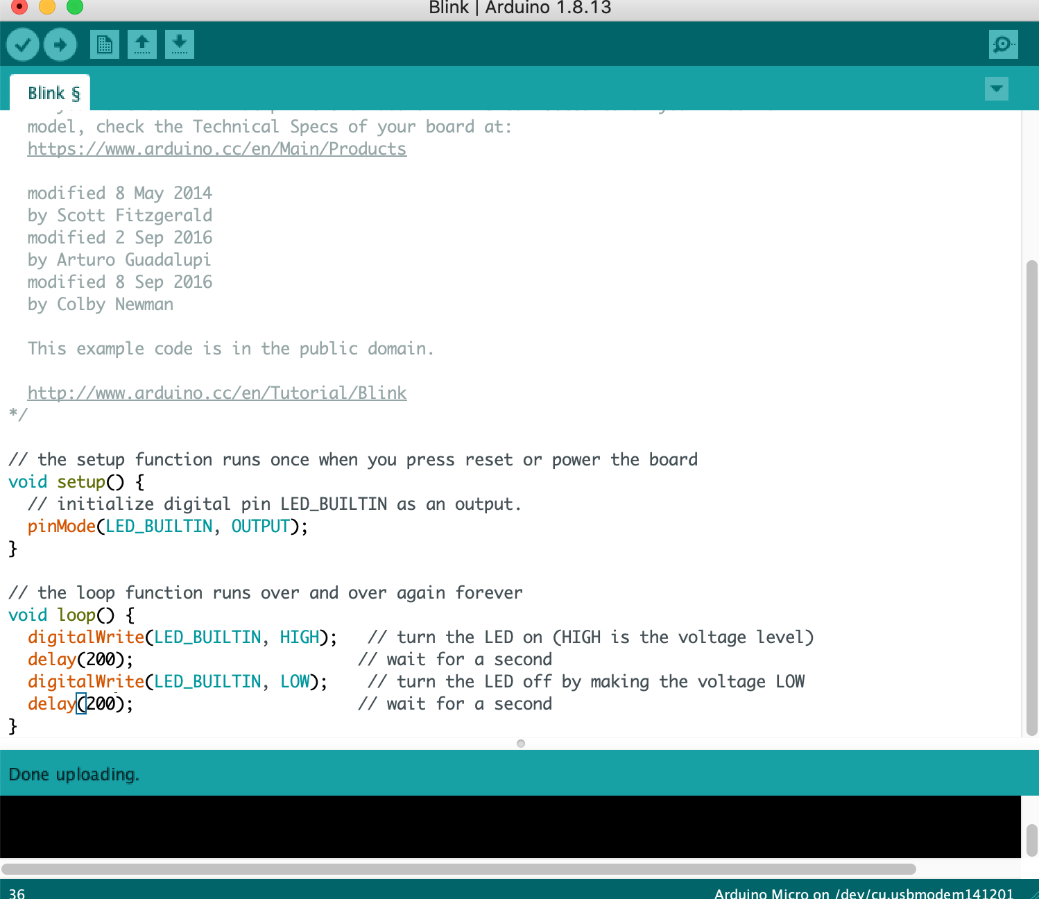
here is the video of the board working:
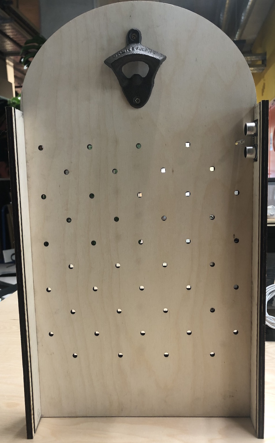
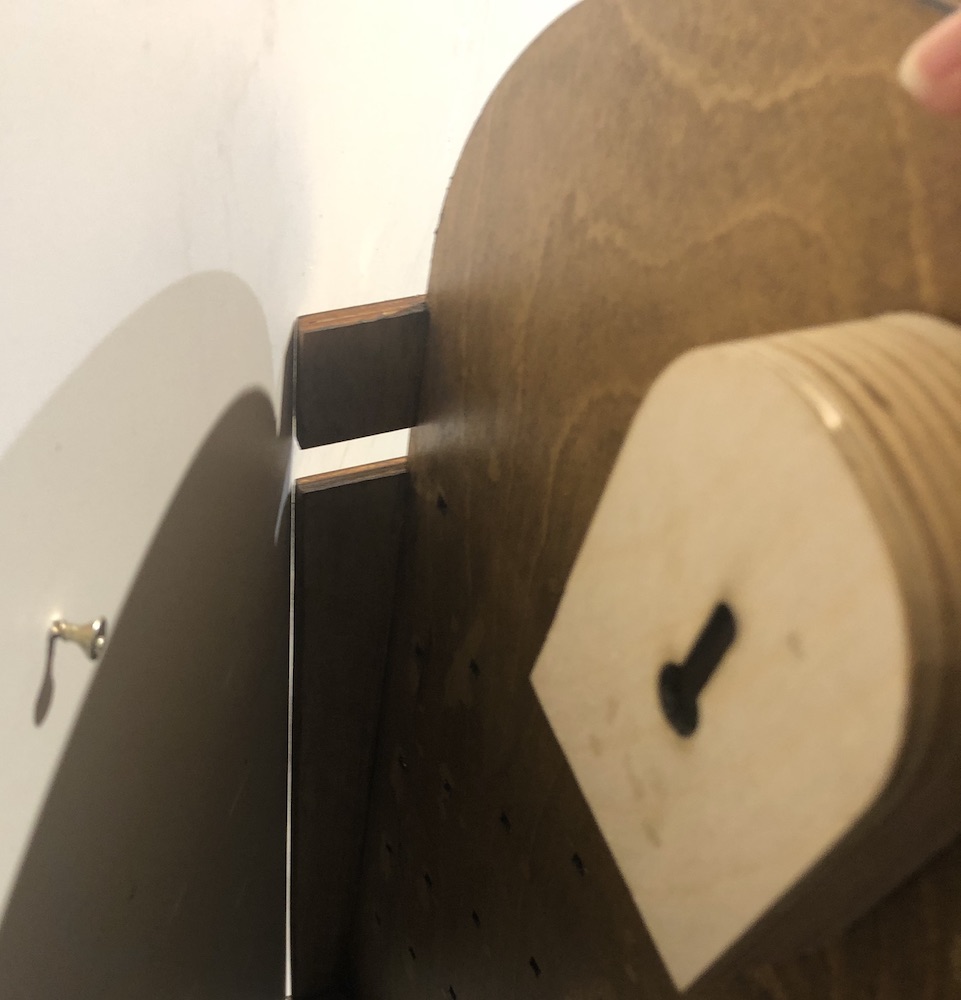
I then had to think about how I was going to hang my project, so Andrew and I had a brain storm as it needed to take the force of someone oepning a bottle and also not move when someone did it. It also needed to be flush up against the wall otherwise the falling of the cap wouldnt work as well because I have tested it flat up against the wall.
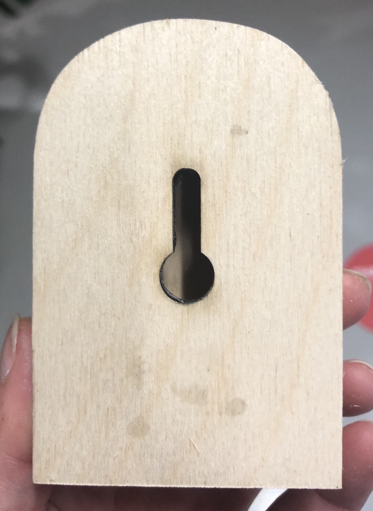
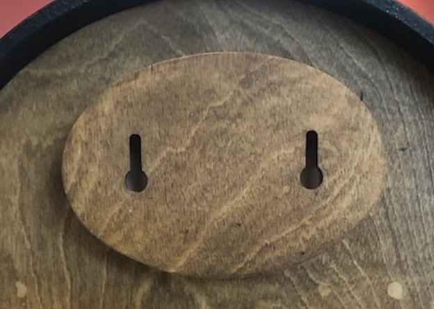
In the end the best idea we had was to have the keywhole design where you screw into the wall and then hook the board over it as shown below.
I then made it out of plywood by laser cutting the shape I quickly made up on cad and then attached it to my game by screws coming through the bottle opener which was a great help as this needed to be secured better than it was.
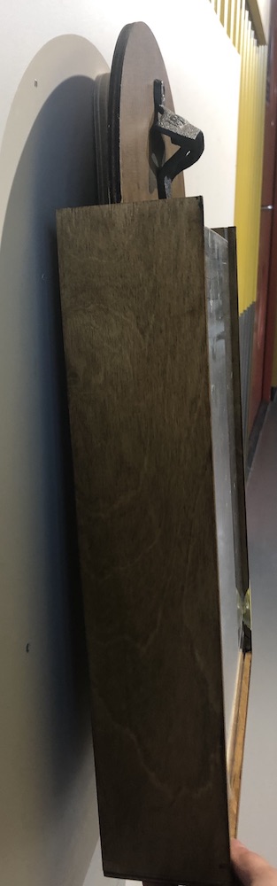
I wanted to test it frst to see if I might need two wholes as thought would work better because it wouldn't move when it was being used. After testing this out I realised I really did need two screws otherwise it moves out as seen in the image below (far right). It also moves to the side too easily and now because I have used it so much I know how to open it correctly whereas I ask another member as they struggled to do it without it moving around.
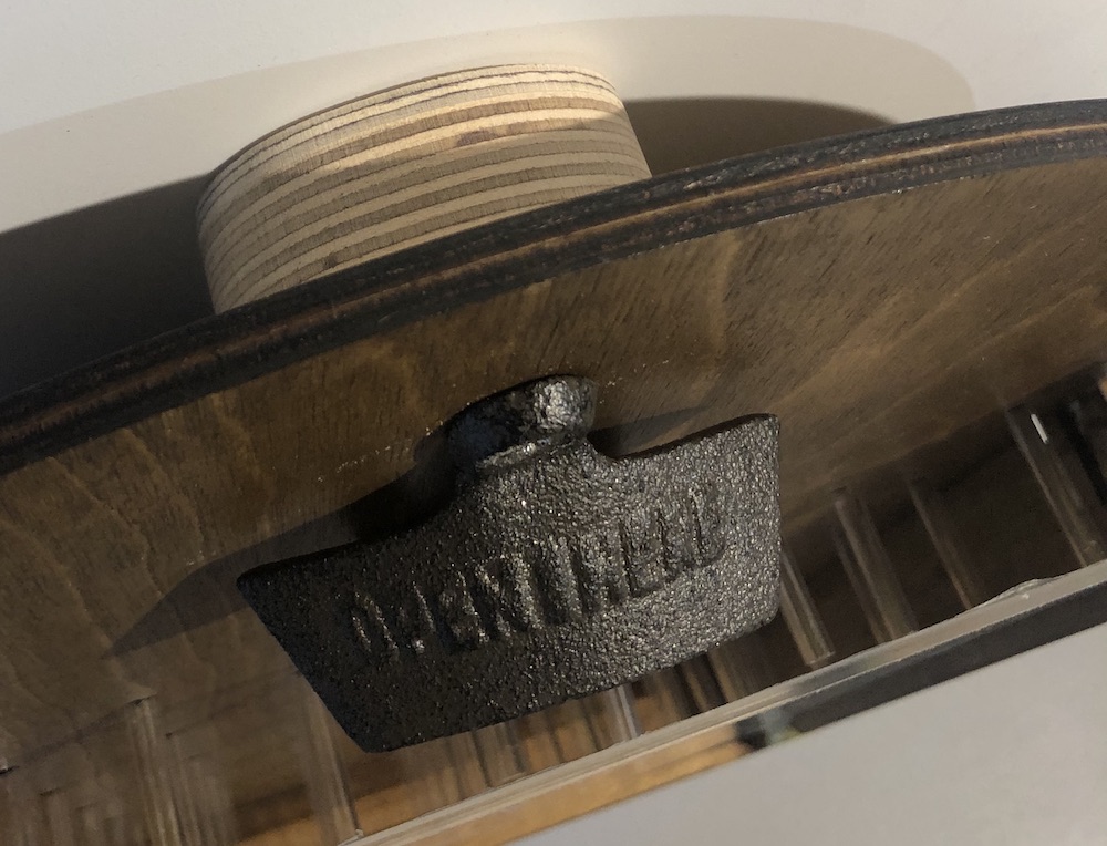
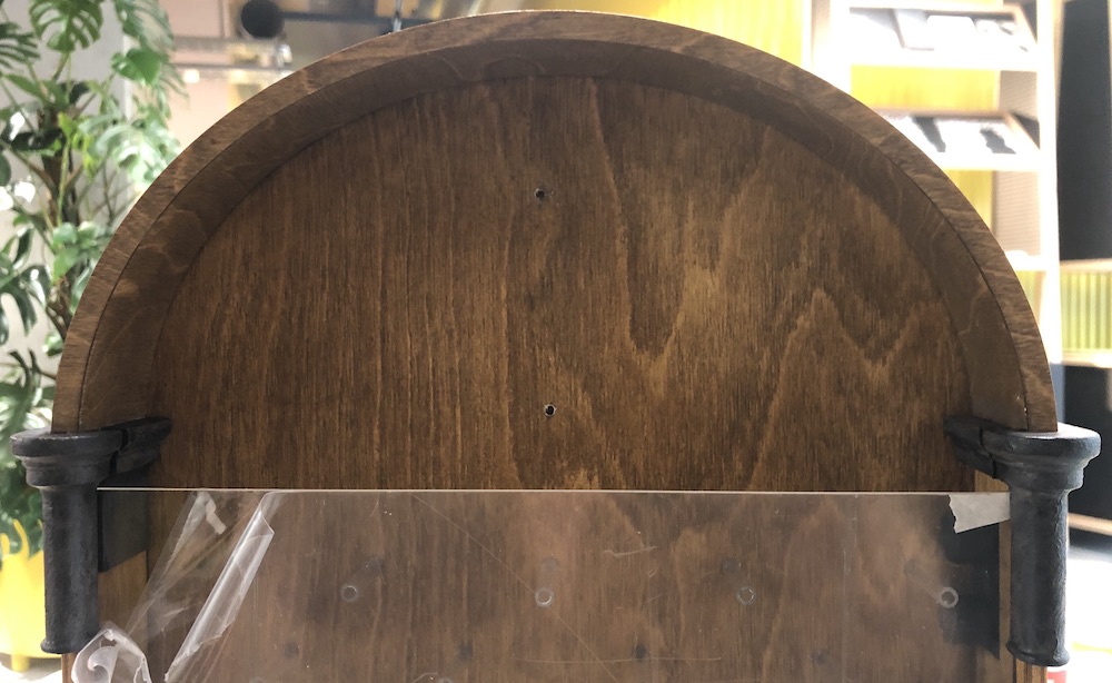
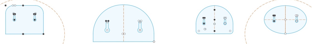
So I went back into fusion and looked into different designes, in the end the oval design I thought worked best so I went ahead and cut it out on the laser cutter, sanded it stained it and attached it to the final body.
It looks good and blends in well I am pleased with the overall outcome.
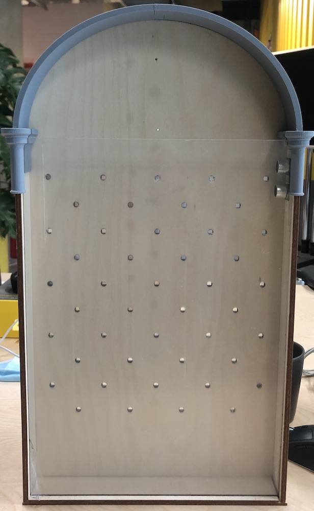
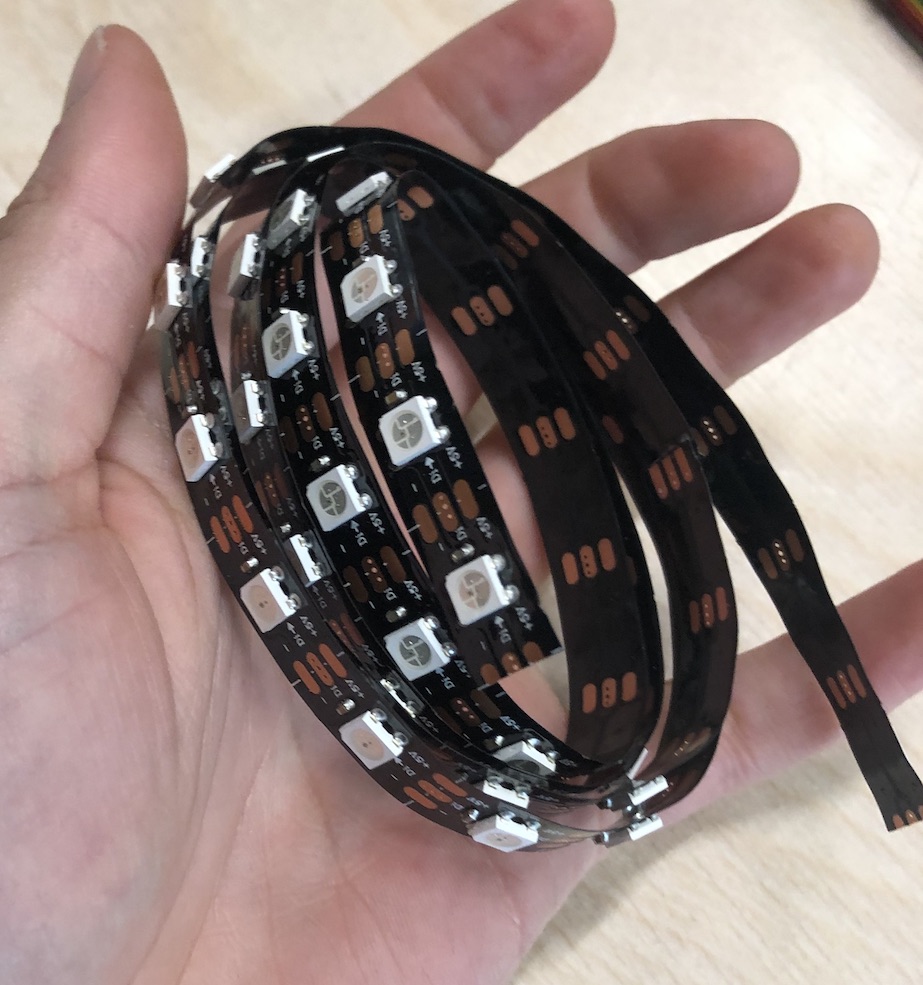
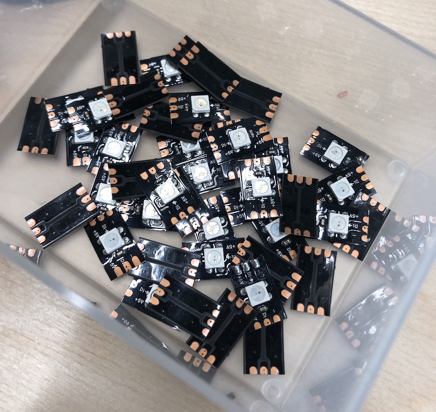
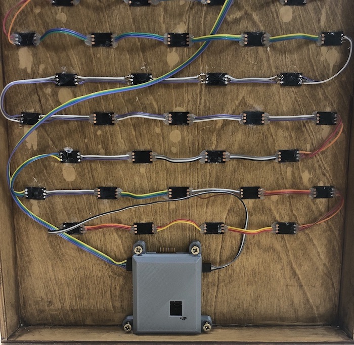
With the neopixels I brought some that were in a strip as this was the easiest way to cut them apart and then resolder them back together in the distance I was wanting. I counted out the amount of neopixels which I needed wchi was 45 and the started to cut them apart making sure to cut at the correct line as shown on the neopixel.
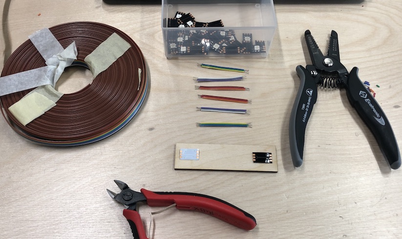
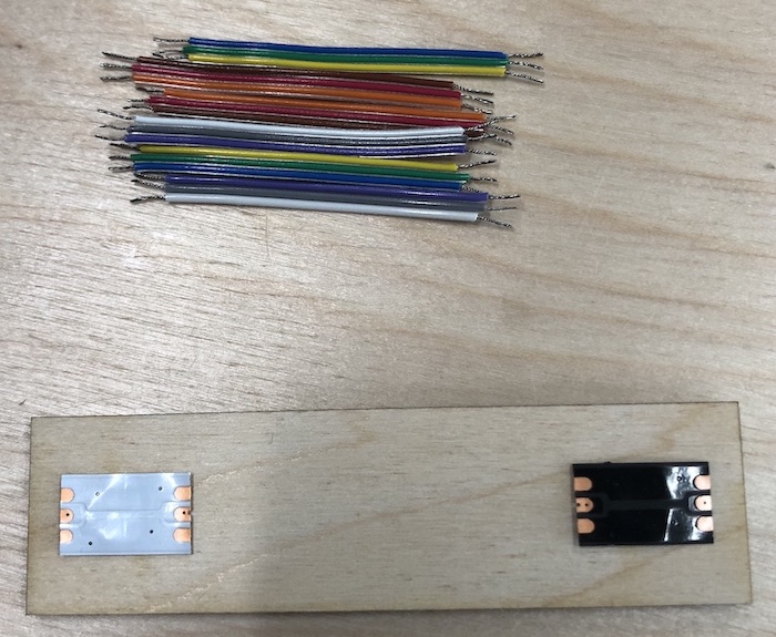
I then started on the ribbon cable and cut all the pieces of wire that was going to be needed to attach the 45 neopixels together. Overall I soldered 270 joins together when doing the neopixels and I couldn't feel my neck for the rest of the day. Took 2 and a half hours to do just the soldering and about half a day to sort out the wiring in the end, I think in the future I will find an easier way to get this done or I'll just pay someone haha!
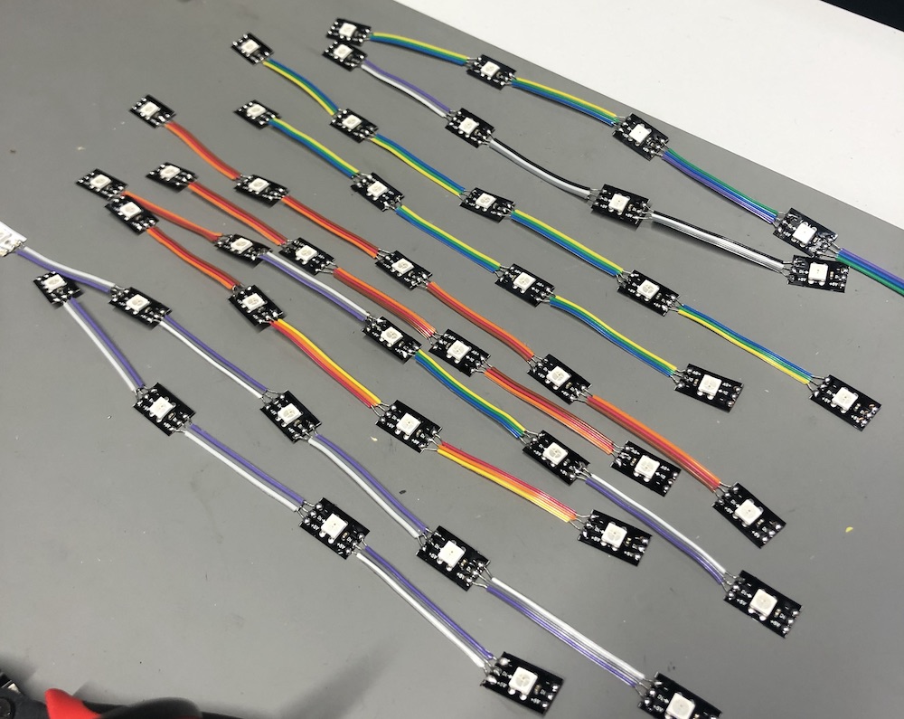
Once it was all complete it did look lovely, I think if I was doing this again I would use the same colour for the GND VCC and + as later on this made things a lot more difficult than I thought it would be. I lined them to up try and watch the colours in a way that would help my brain and then soldered the edges together so that it was one long line, making sure they were all going in the same direction.
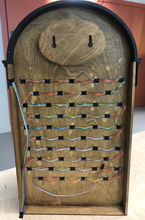
I then moved them onto the back of the board and glued them together. Overall this worked well but I as a little cocky and should have programmed them first before glueing them on, I had some big issues with the first few rows only lighting up and then after that there was another issue of short circuiting because I have some wires over lapping. To prevent this from happening I added hot glue over the soldered areas to prevent them from short circuiting but also this will help them stay strong as it is a fragile join.
![]()
![]()
The back is looking good and clean which is just what I wanted with everything at the back coming together means that I now need to find away to attach my circuit board.
I then tried the neopixels with the sensor to the side of the board and this didn't work please go to testing sensor page to find out more.
Here is a video of the chosen place I ended up moving the sensor to as this was in the best result from the other areas tested:
I then went into fusion and designed a new sensor you can see my initail ideas on testing sensor page.
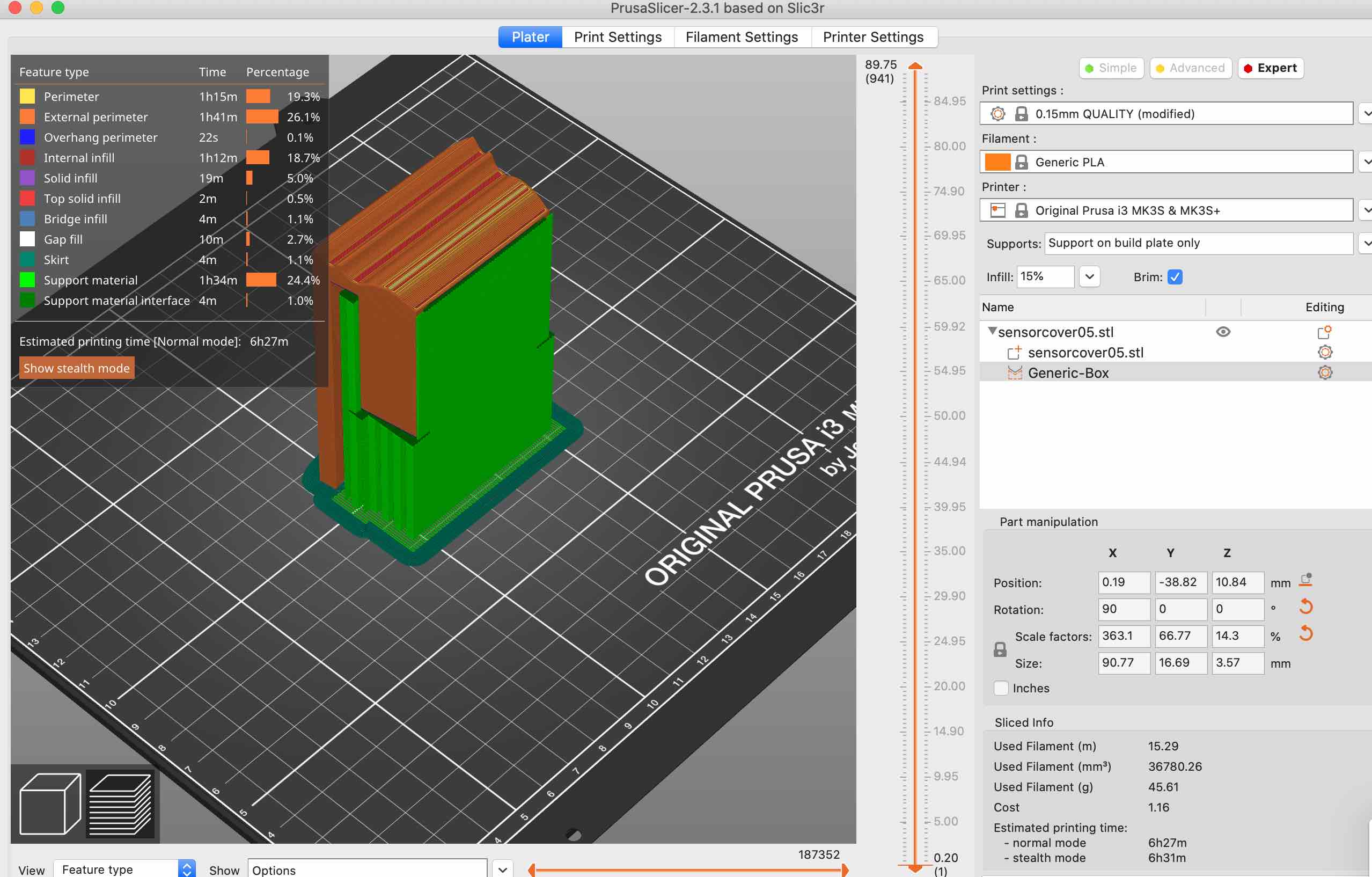
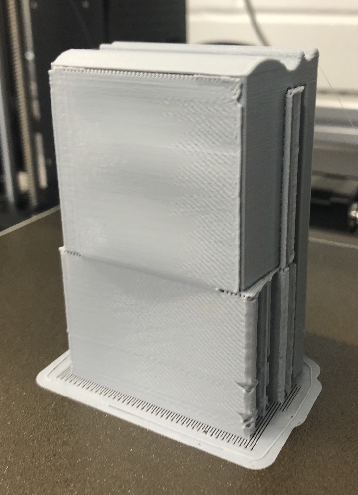
I had a few issues with this print, as it took quite a long time and my testing wasn't very accurate at the beginning I was doing this late in the last weekend before I had to present. The print had been going all day and in the last 20 minutes it failed! I left it and printed one over night with my fingers crossed and lots of supports, it was the exact same print and in the morning I came to it all complete and I was very happy.
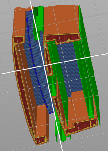
It printed very well with the correct arrangement, I think if this hadn't of worked I would have tried to do it in a few different cuts to see which one would work.
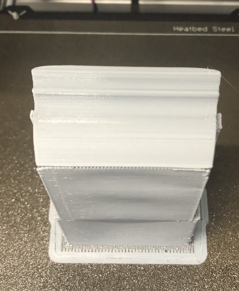
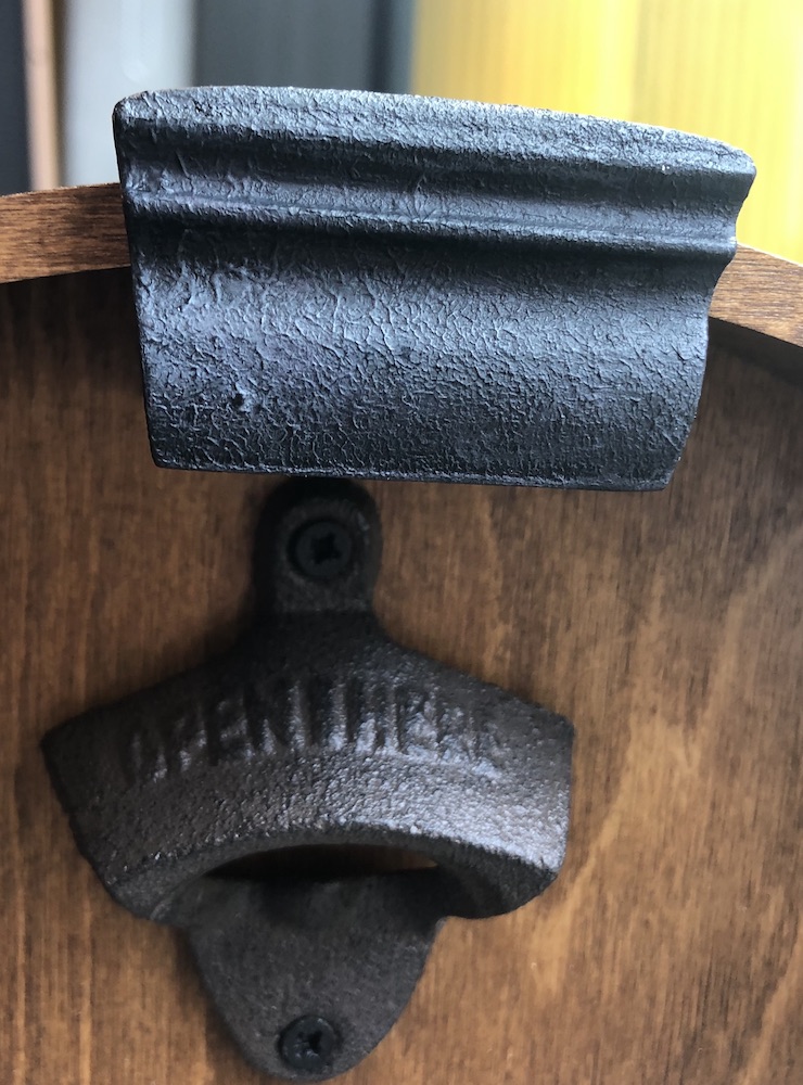
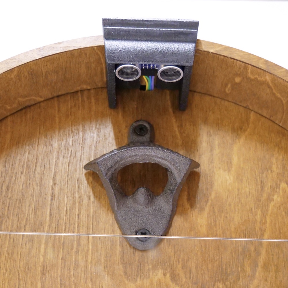
I placed it onto the arch to double check it fits well and doesn't slide around, I also checked if the sensor was far enough away from the bottle opener to not sent off the lights all the time.
I then put wood filler on it and sadned it dowen, primed it and then painted the exact same way as the moulding edges, I think in the end it came out very well and you wouldn't be able to tell it was done after the side moulding.
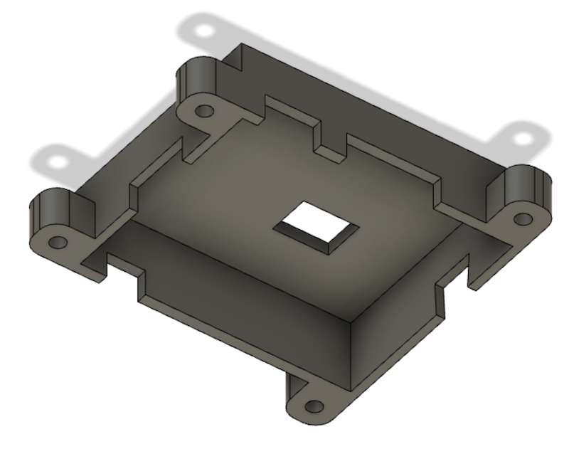
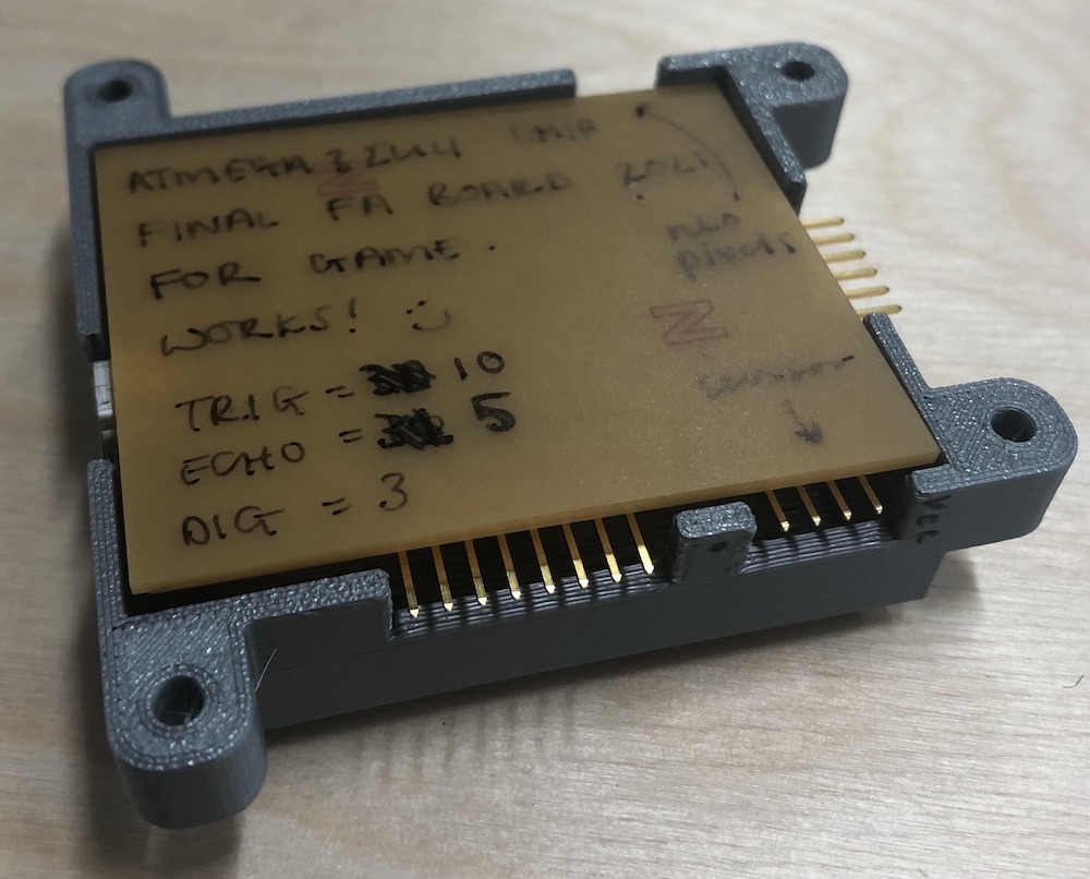
To make the case for the board I started by measuring the board itself and adding where the wholes needed to be in my sketch book. I then went into fusion and started to design it up with these measurements in mind.
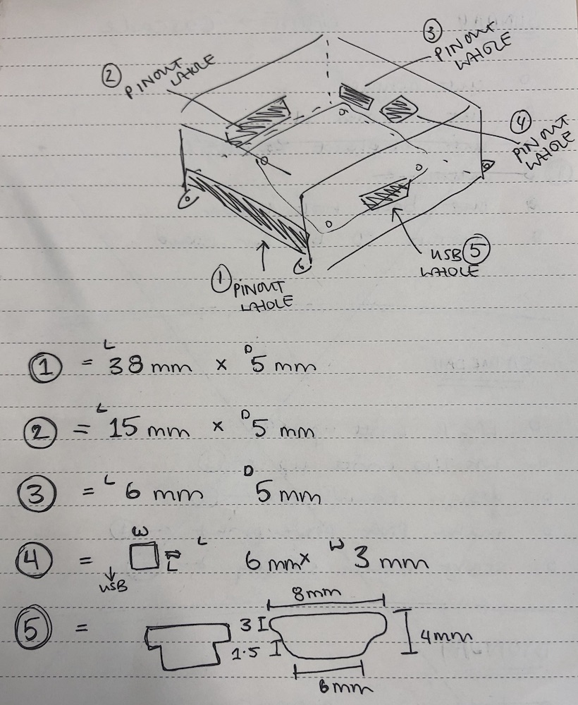
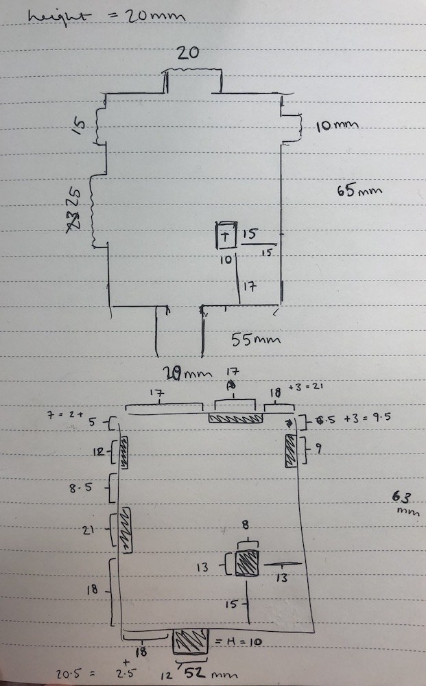
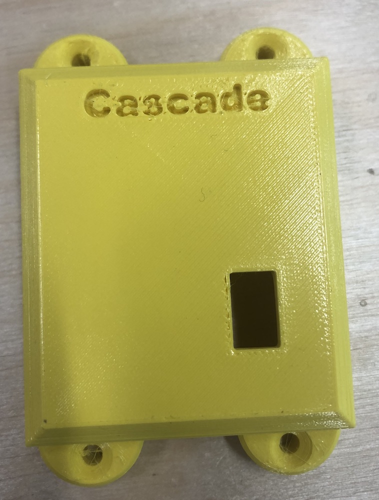
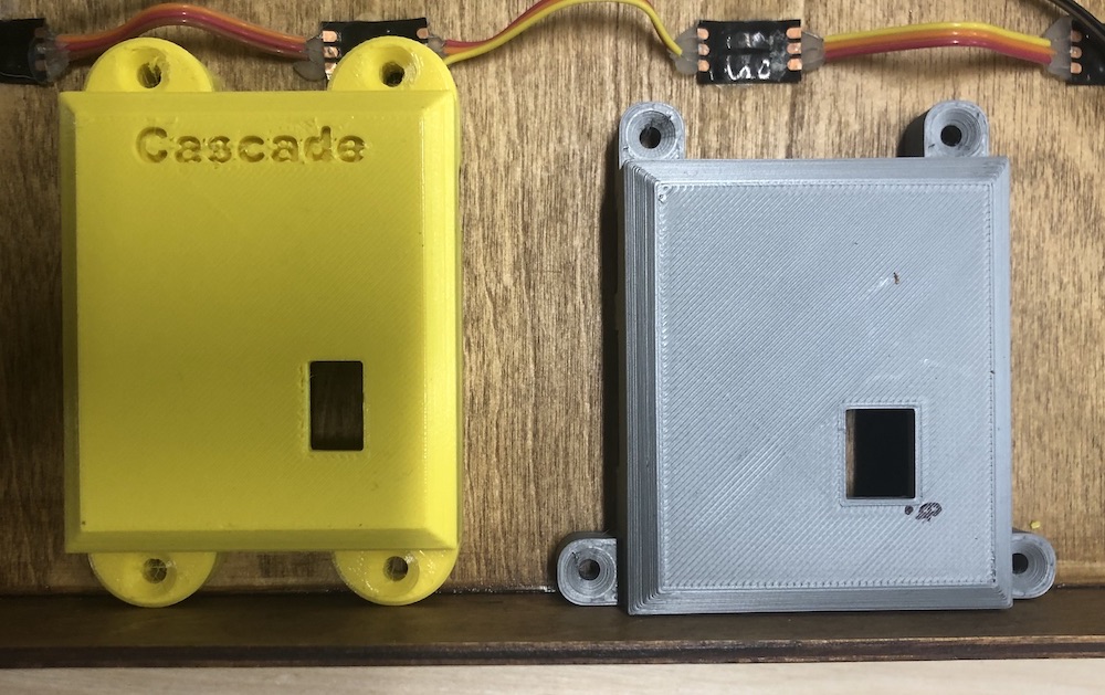
I added feet to two sides and then added 'Kascade' to the top as this is the name of my game. Unfortunately the board doesn't fit well on my game as I didn't think about positioning very well at all! I also put my board in place and some of the parts were slightly out of line, the main one was the area for the USB which is actually in between two of the screw wholes. This was a design fault on my side so I decided to make a new one taking into consideration of all of these things, I also didn't like the look of it, the feet were too chunky.
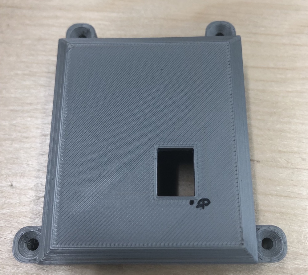
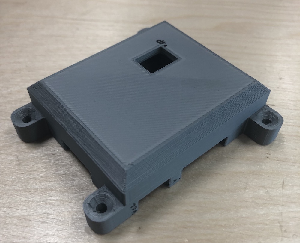
In fusion I redesigned it with the feet being smaller and the wholes being the correct spacing and size. By moving the feet to the side this also means that the board can but up to the edge of the game at the bottom much better compared to the other one.
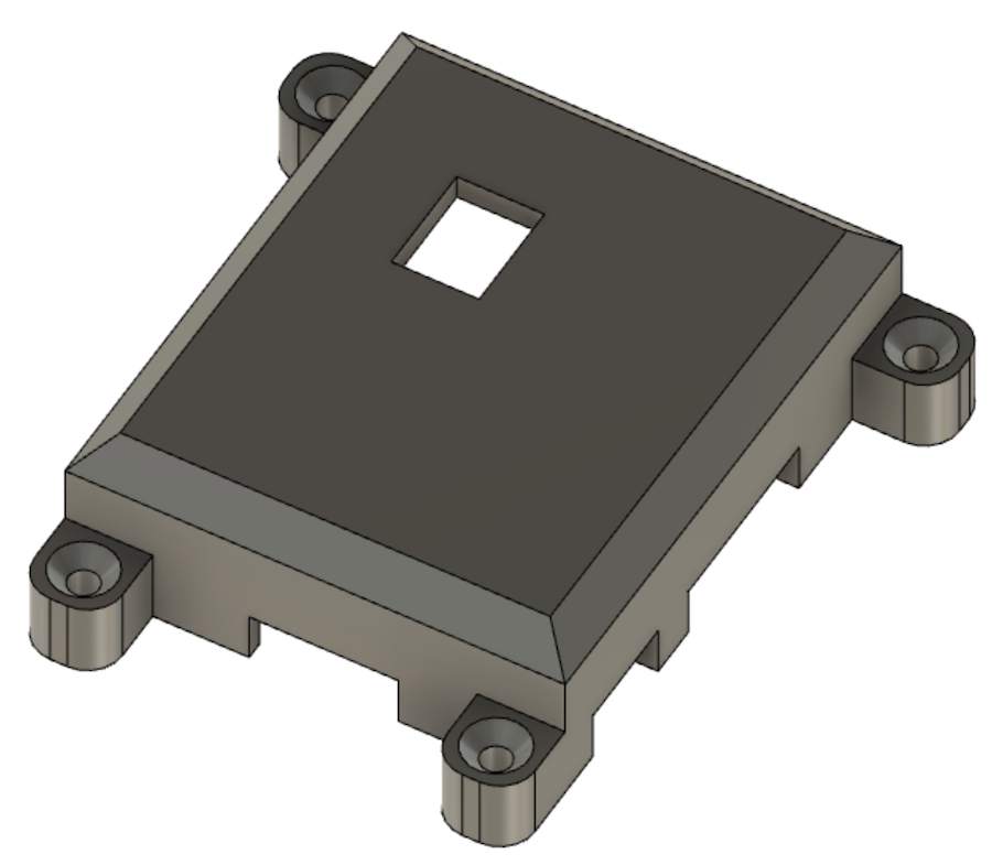
As you can see the grey one sits much better inside the space, I just didn't think about the positioning of it on the game but rather where the feet were compared to the wholes for the pins.
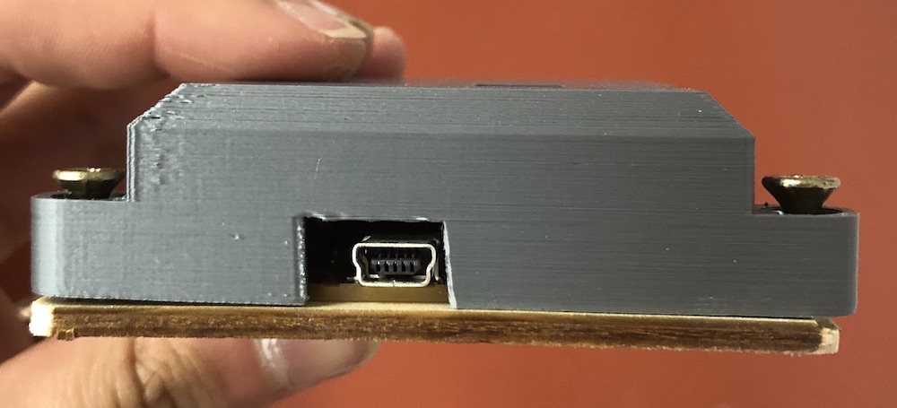
Here are some photos of the casing and the board inside the casing as it fits so well, I do wish it was a little thinner but because of the large capacitor this was not possible but overall I think it looks smart and secure. You can also programme it inside its casing as I have left a whole for the rainbow cable to slot in.
I also then deciede to make my own wires to connect the neopixels and sensor to the board rather than soldering them together. This mean they will be stronger and as a processes it is very fiddly but really fun to do when you get that lick in the end.
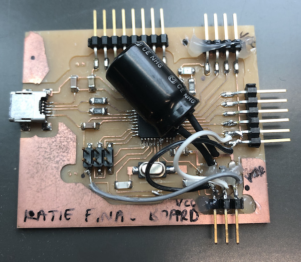
I hadn't attached it to the back of the board yet and in doing so had ripped off the traces on the 3 pin header for my neopixels. I glue gunned the 6 pin header back into place and then checked what was still connected by using a multi meter and two traces weren't working. 1 from the GND pin and the other from the digital pin, I just added some wires going across the two and then added more glue so that it couldn't come open. I checked all the connects before glueing. As you can see from the photo I also did the same to the sensor pins just in case in the future.
I then placed it in the box and screwed a piece of wood so that it was secure as at the moment I can't attach it to the board until I have hung it up and the cable is coming out. I also lines up the same wire colours as the wires I made so that I would know how to line them up in the future.
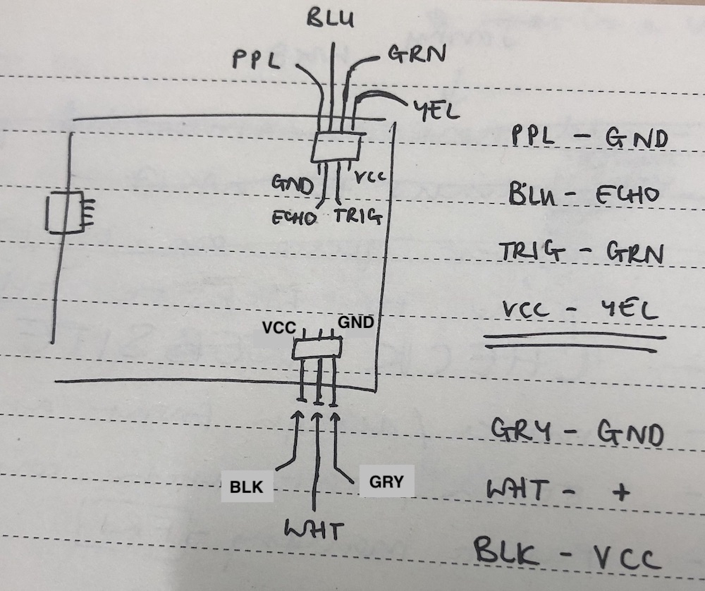
During global evaluation I was shown how to fix my board properly using the wires and where to connect them to. I therefore removed the old sodering wires which I had done and attached the new wires correctly. In doing so I changed the pin number for the digital pin which is now 4!
yuichitamiya showing me the correct wiring for fixing my board image:
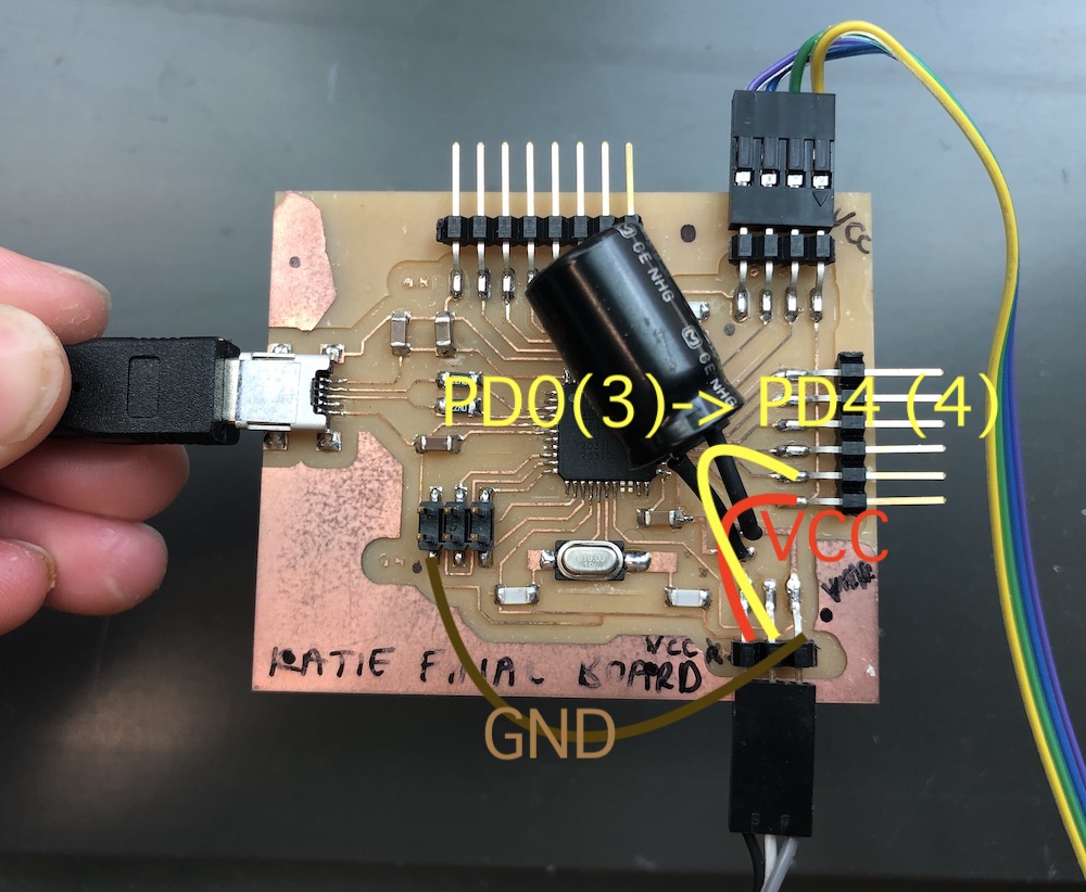
after following what yuichitamiya showed in the image abooe of how to fix my wiring issues.