Link to Networking and Communications Group Page
SPI and an I2C - these are the most common
Addressing is making it more clear = so pointing out who to specifically send the signal too rather than just sending it over and hoping it hits the correct chip this is more networking.
In arduino it is called wire
Multi master and multi secondary
They used to use master and slave as the two ways you communicate between the two boards but its has now been changed to:
Just need two pins
= differed positions
= very simple relationship between them all in a line
Library is negotiation of who is responding and receiving data which is part of the communication.
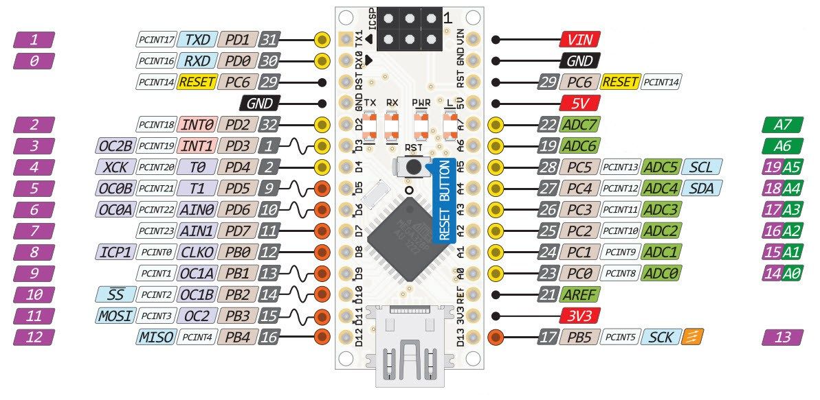
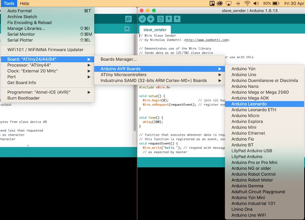
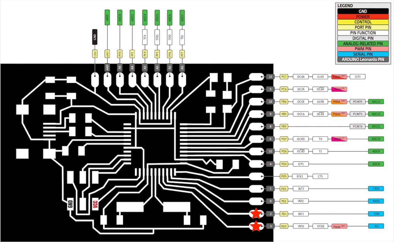
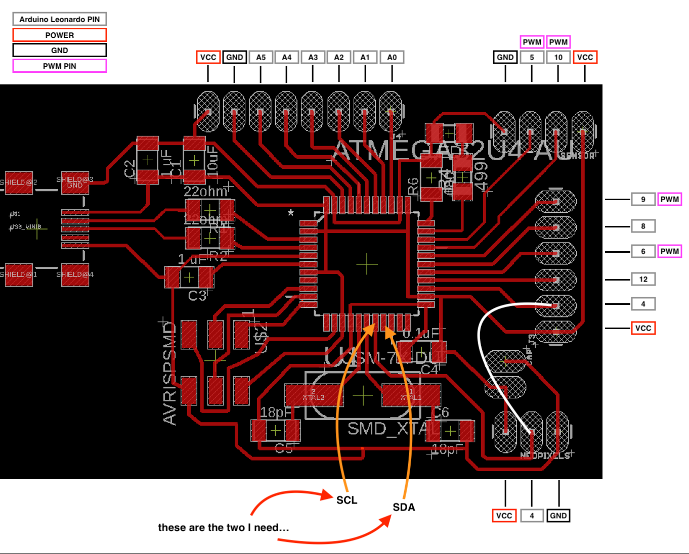
I will need to use the A4 and A5 as these are SCL and SDA
Figuring out which pin outs I will need on my board:
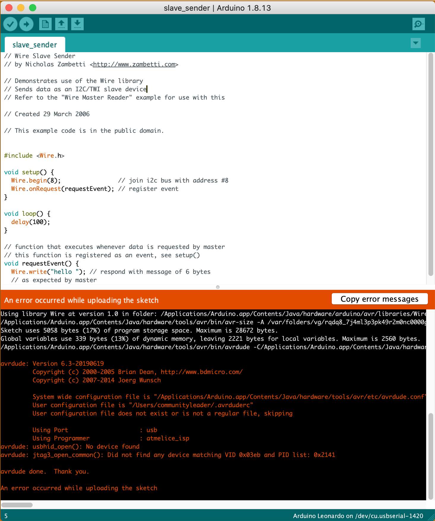
This is now coming up as an error?
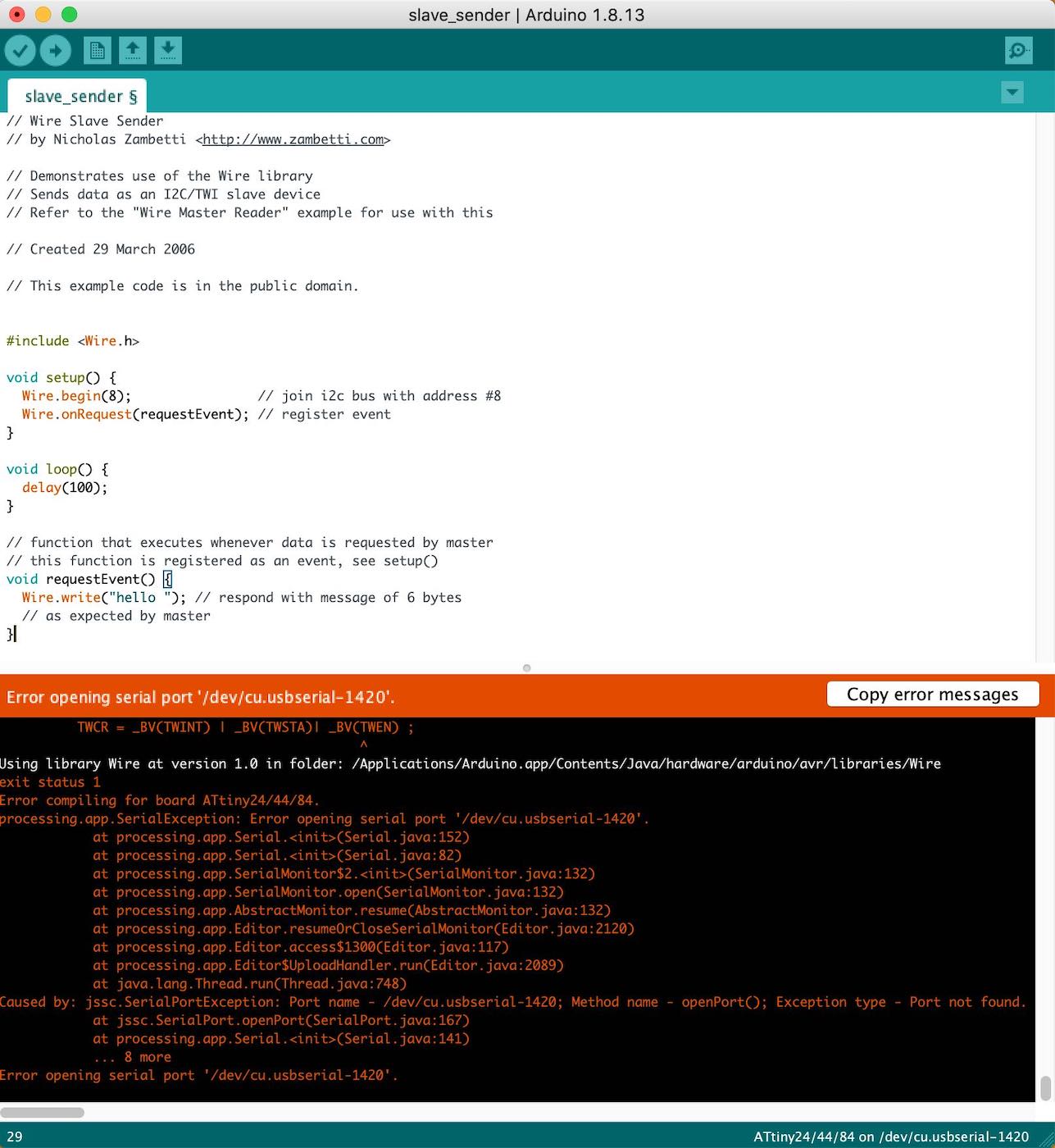
I forgot that my ATtiny44 doesn't like 'Serial' and will not work with it, when googling it earlier during this processes a lot of people said to upload something else to help it work. I thought I might as well make a new board that supports 'Serial' as I might need it in a later date AND I know the ATtiny44 doesn't have enough storage for me and my programme I will be uploading onto it.
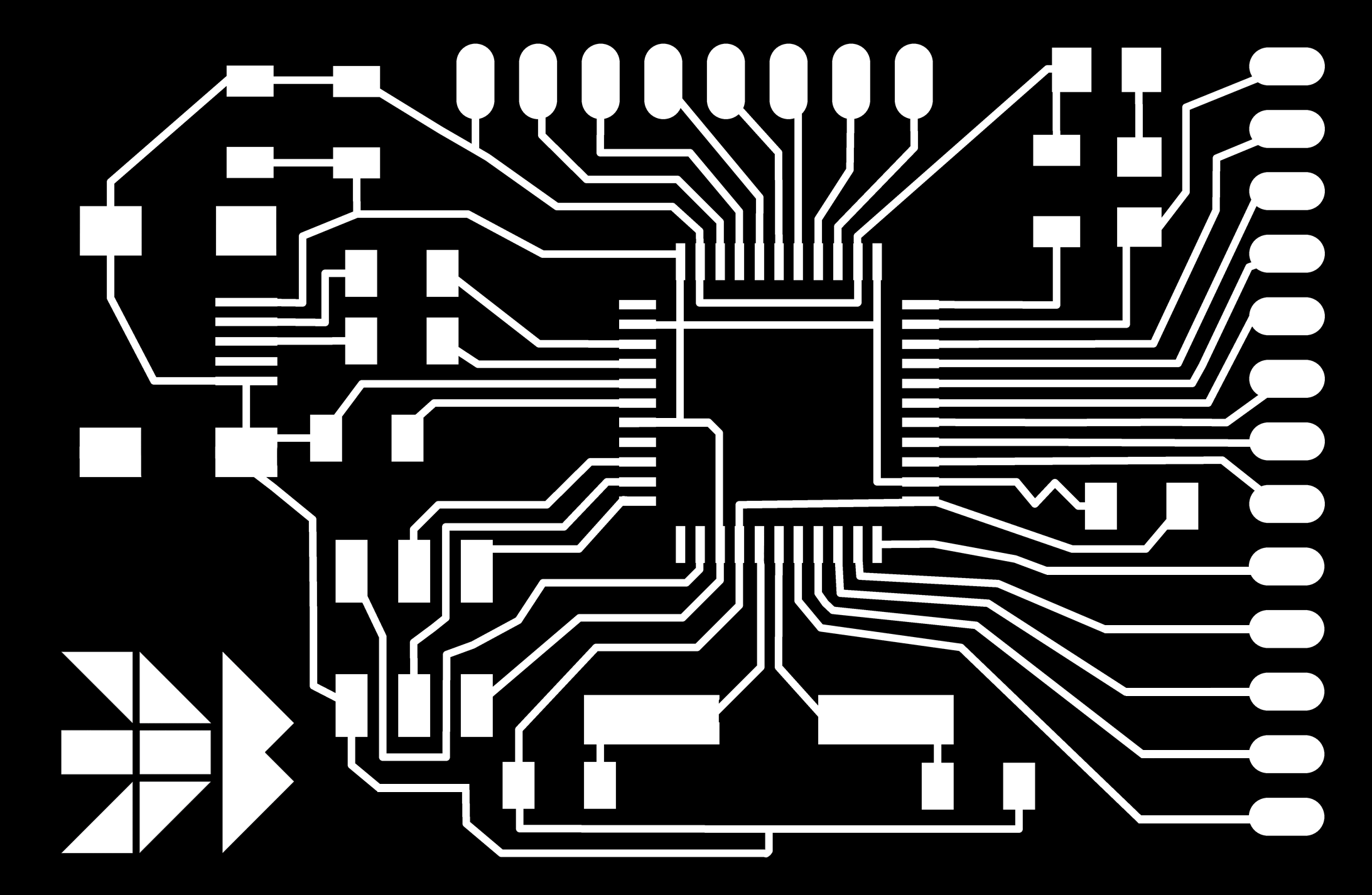
After my ATtiny 44 wasn't working, speaking to Andrew he suggested to make this board by Luiz using the 32U4
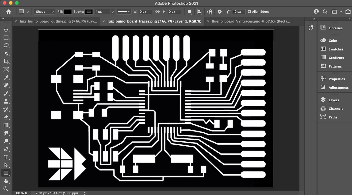
Luiz website is amazing, he gives you all the information that is needed to make this board plus shows and explains what parts he uses and why. See bellow for his traces, outlines and all the extra information to build this board.
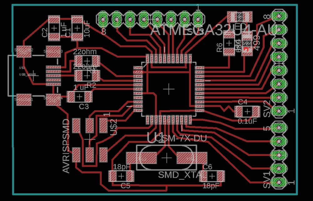
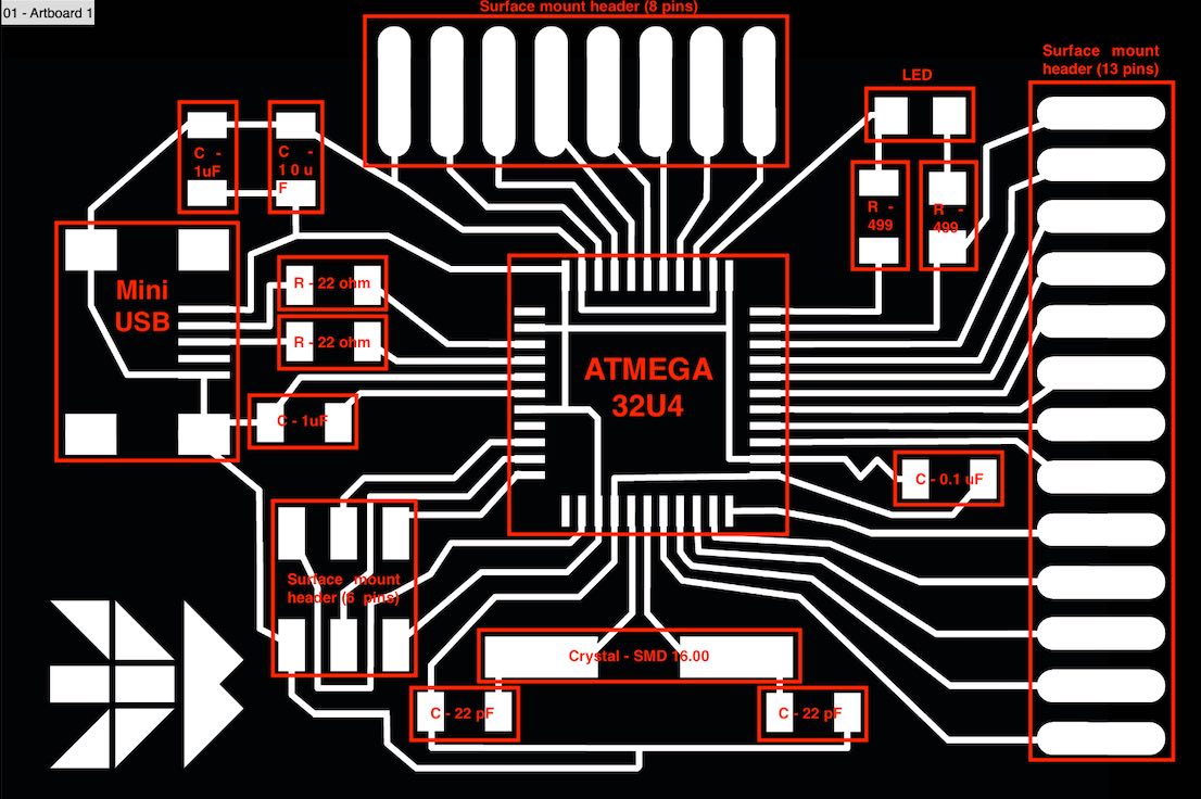
Luiz Traces:
Board Schematic:
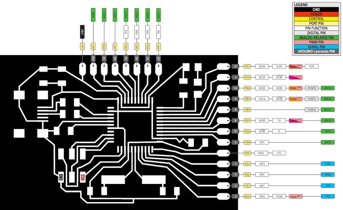
Showing the pinouts on the board for the 32U4 - this was a huge help!
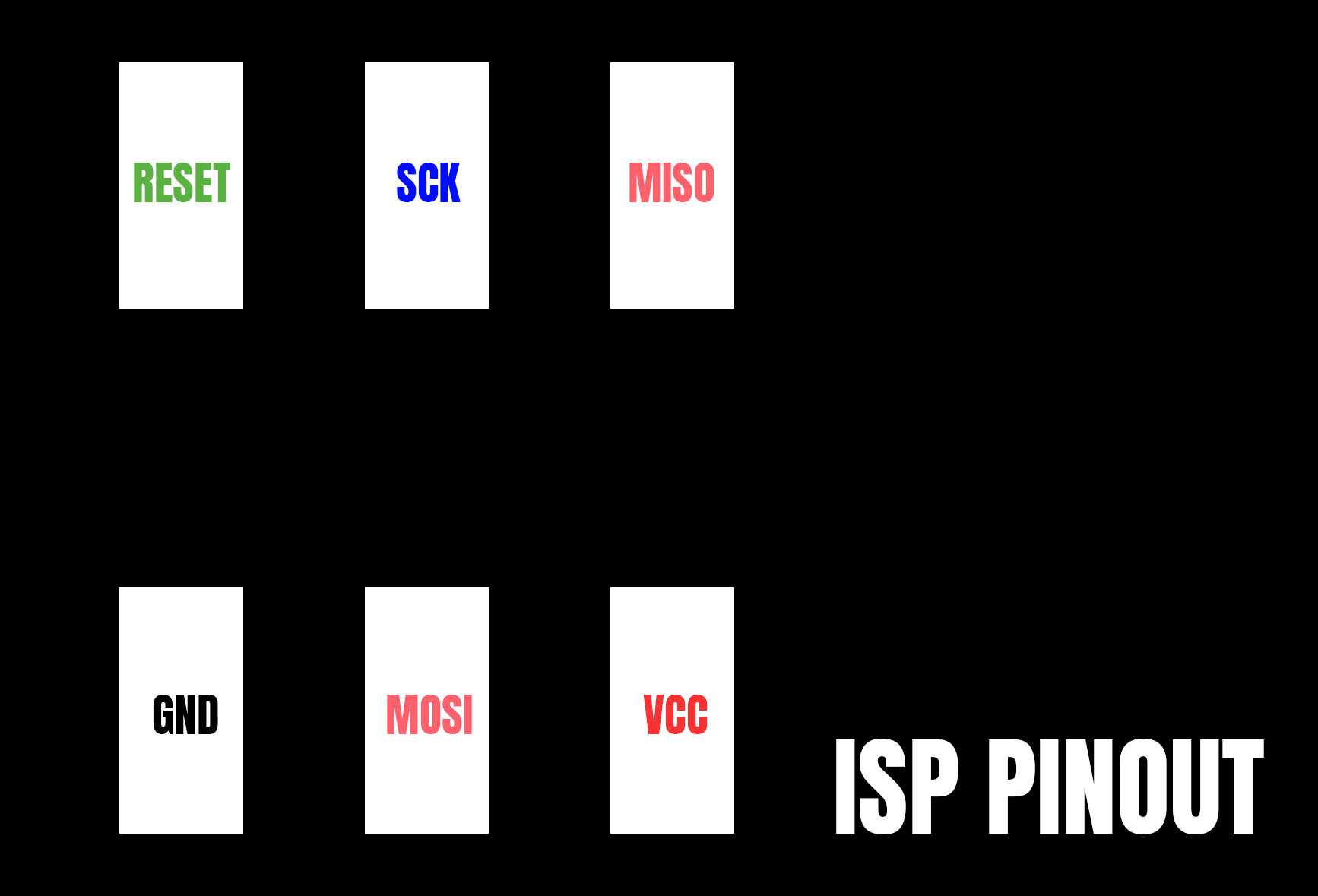
ISP pinout:

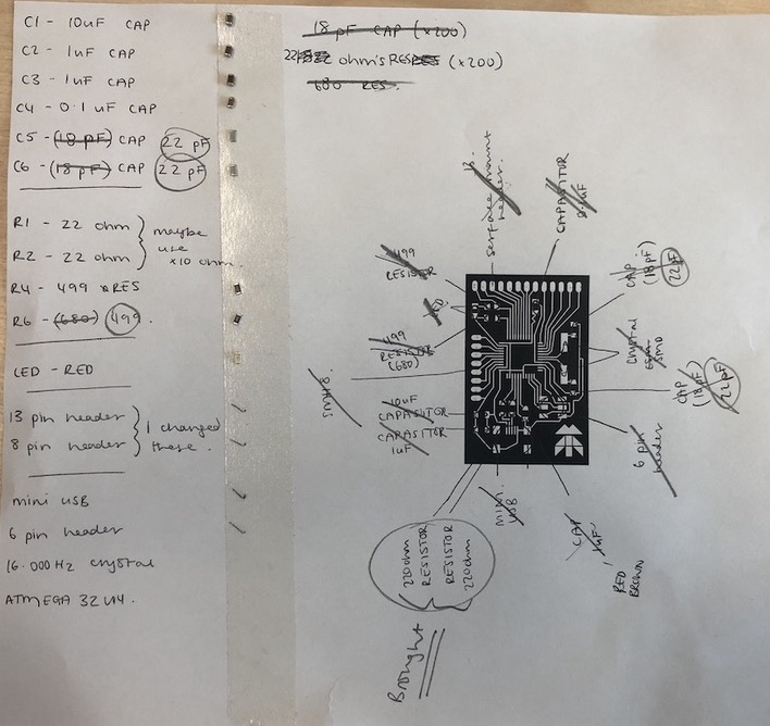
All the Components are what Luiz suggests to use, if you check his website you can see you deinfalty need to use. I
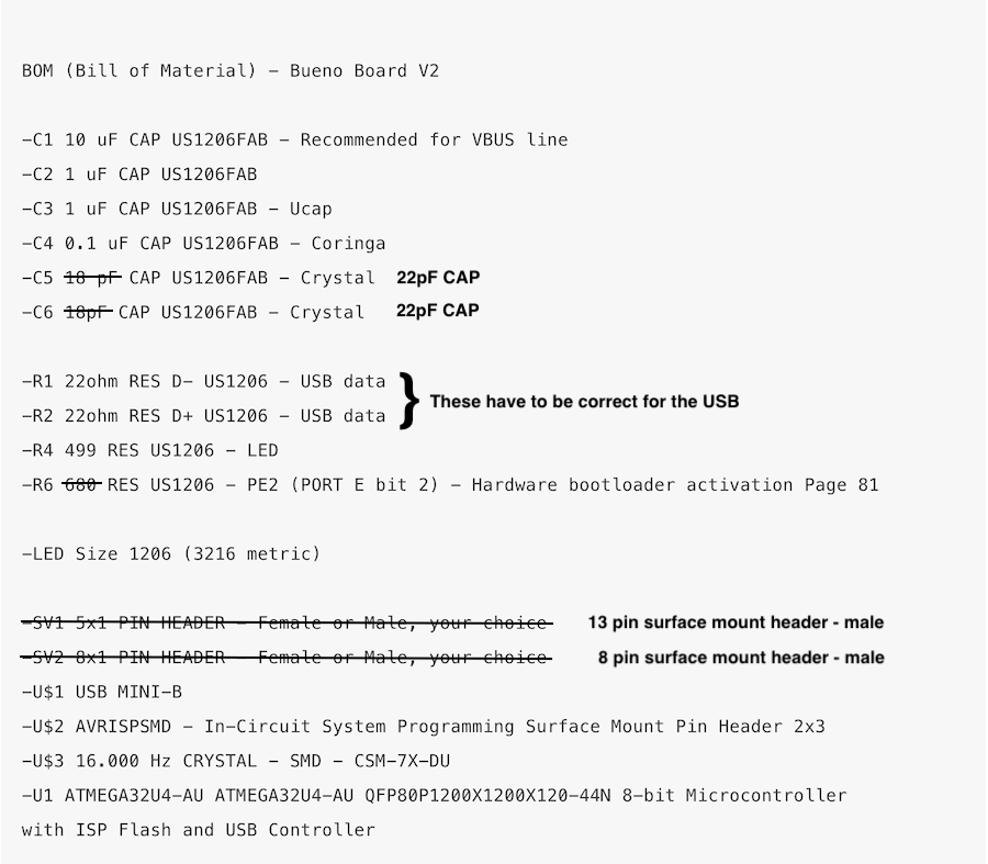
So we didn't have all the components that Luiz had, I kept reading down him page to see if they were all needed and as shown above I changed a few so that they would first fit my board. As I didn't want to do any through whole soldering when it wasn't needed. Also we didn't have any 680 resistors so I just used 499 resistor as Andrew said this would be fine.
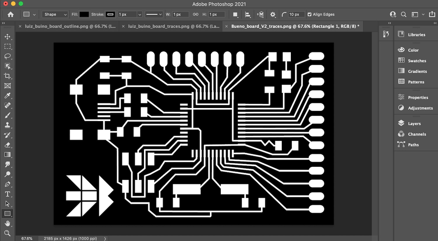
I had to change the footprint of the board as the surface mount headers we had were not the same as the one that Luiz had in his. I made it so they were bigger and also the size of the outline as this was different once I had changed the footprint of the pads.
I had to adapt Luiz board in photoshop so that the footprint of the surface mount headers where in the correct place. This was very simple and back you can layer up the images this meant I could line up the traces and the outline so that they would cut correctly. Before this time I was using preview which was very difficult to do this with, I would hightly recommend photoshop for this use as well as using it to adapt photos.
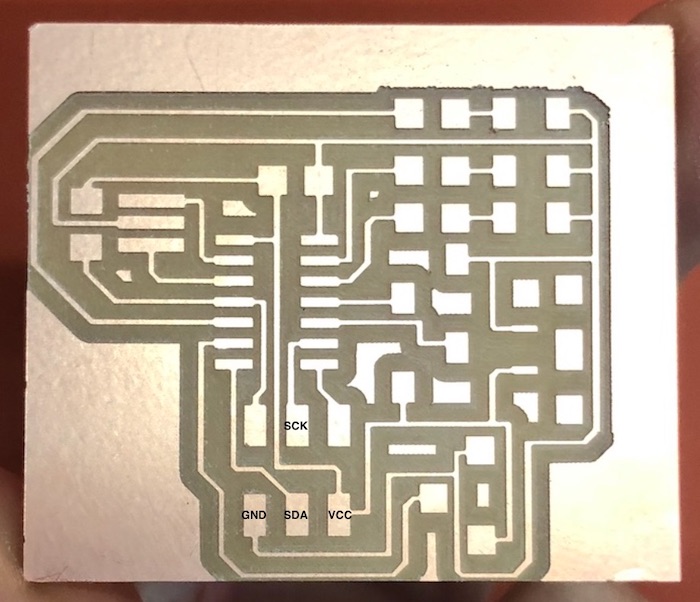
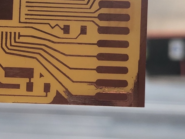
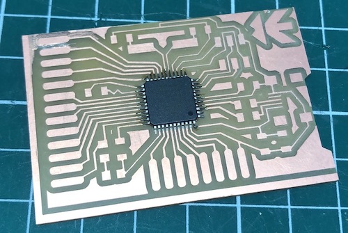
The board cut very well on the SRM-20:
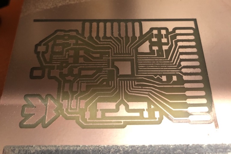
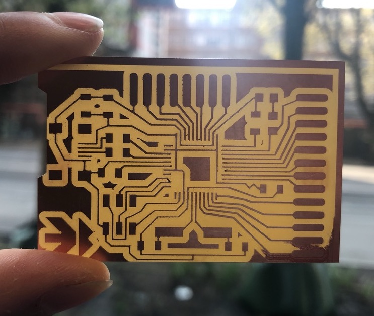
For some reason on one of the edges it didn't quite cut all the way through the copper so I got a scalpel and just picked at the edge, then got the multi metre and checked there was no short circuit.
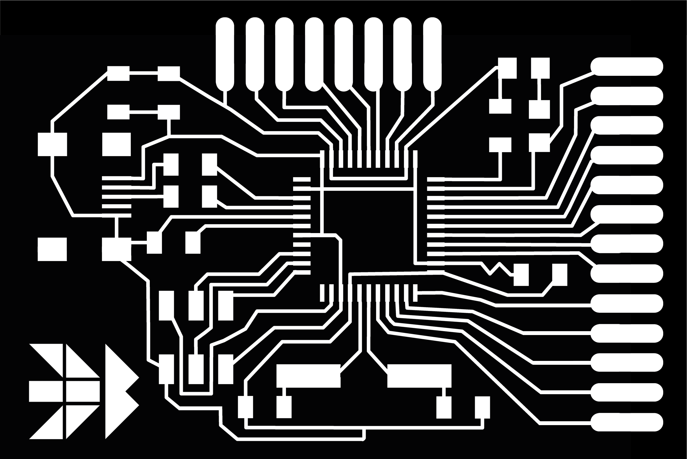
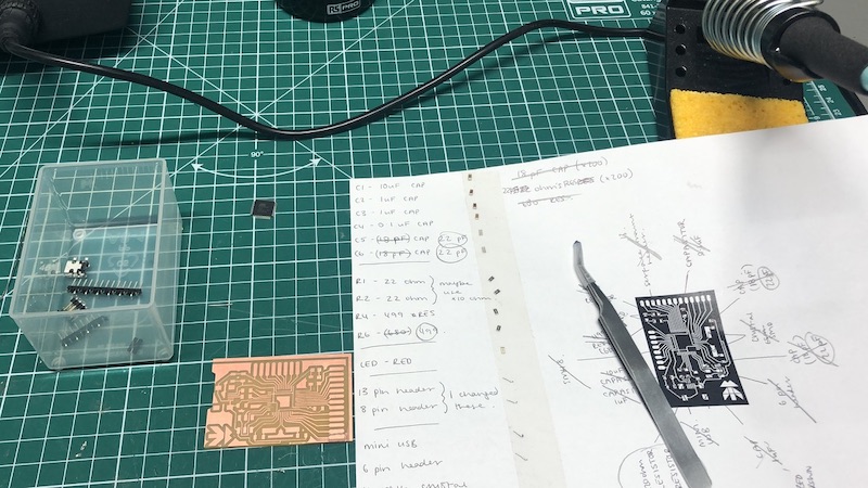
I got my traces and put all the components in the places that they needed to be so that I could just follow this version which I found a lot easier that following Luiz schematic.
I then played everything out so I could see what I was going to be doing and started with the chip.
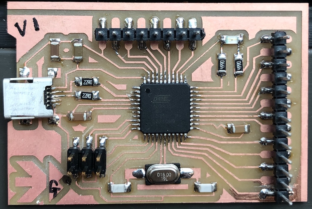
This was the hardest soldering I have ever done but I found a good technique that helps me when it comes to the smaller more fiddly parts. If you start from the furthest away from you and then work towards you you prevent touching the other pins and getting a short circuit on them. I also find it a lot easier to check each component with a multi meter as I go so that I can see what issues might come about then rather than later on. This helped me realise I had short circuited around the chip and all I had to do was get some of the solder off that area. This was a great way to do it so that I wasn't going back on myself later on when all the taller components are attached to the board and making it harder for me to desolder the part.
With the board complete and from my understanding everything is soldered correctly I went onto programming it...
Using Luiz Website I followed what he did. I used our Atmel- ICE (click here to set up Atmel-ICE to Mac from wk13 ) as I didn't have another programmer that would work with this board.
On Luiz website he explains it very well but you need to make sure your ArduinoIDE is set up correction:
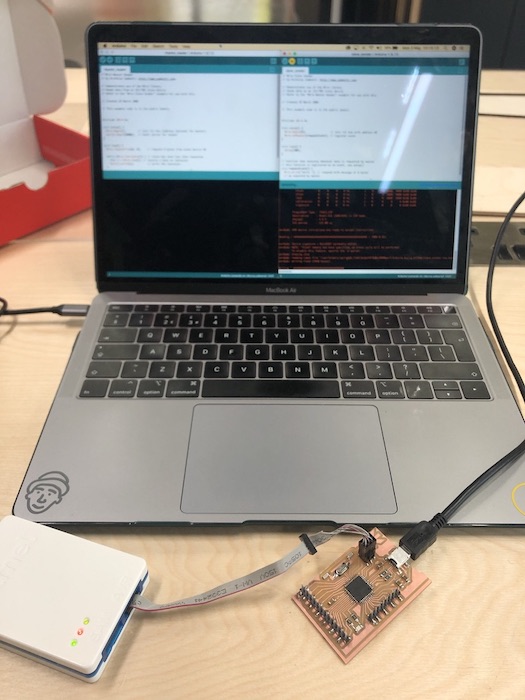
I did something silly and got the two boards the wrong way around!! So I had the Atmel-ICE connected to power and then my board connected to the computer… Silly Katie!!
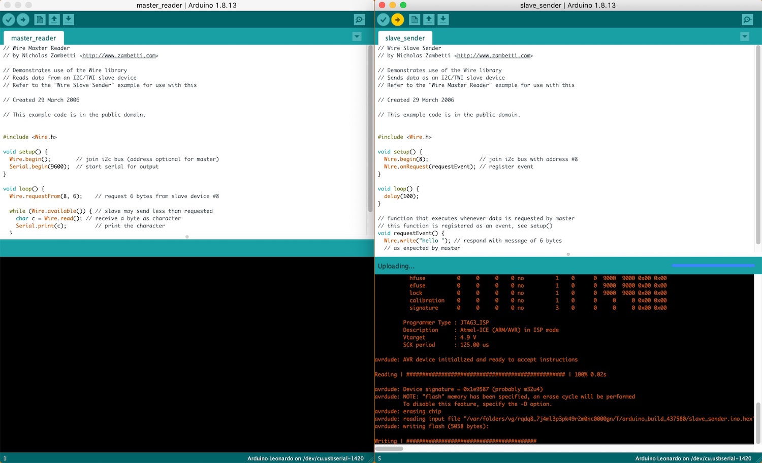
I changed them around and it worked!!
I honestly think reading 'writing####'' is one of my new favourite things to see when I am using arduino.
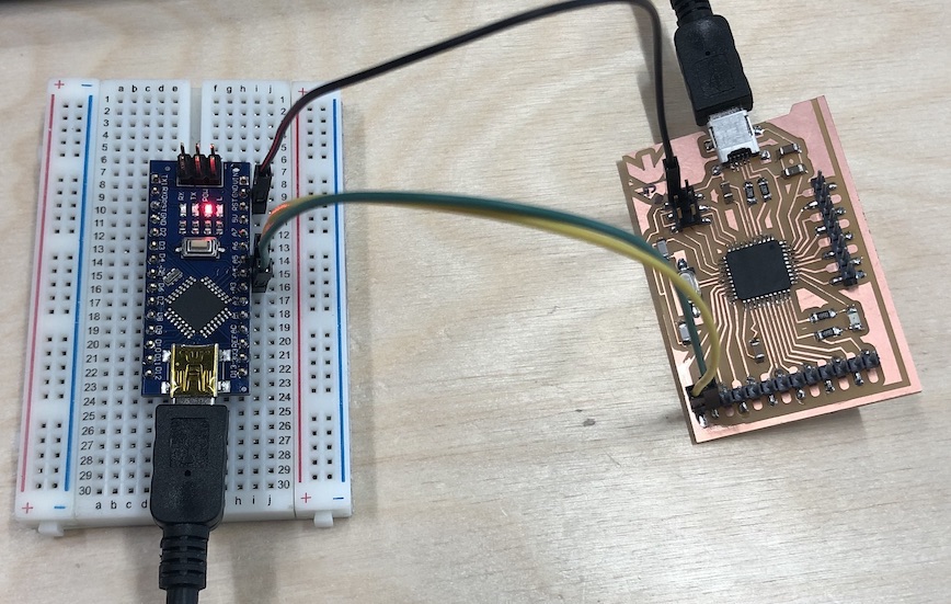
So I need to connect the two board together by using the GND and the SCL and the SDA together.
Luiz had gotten the layout for the pinout map from Daniele Ingrassia which is the photo below and had been huge huge help during this processes as getting to know the pinouts for this board is going to be a long and hard game!
I have placed red stars on the two I will be needing as shown below. . .
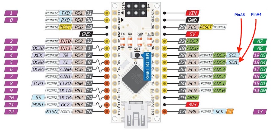
Pins that I will need to find on the arduino nano:
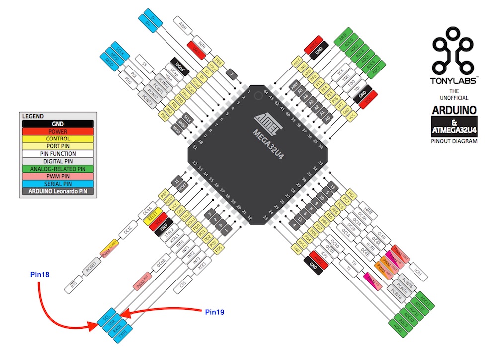
Pins that I will need to find on the 32U4:
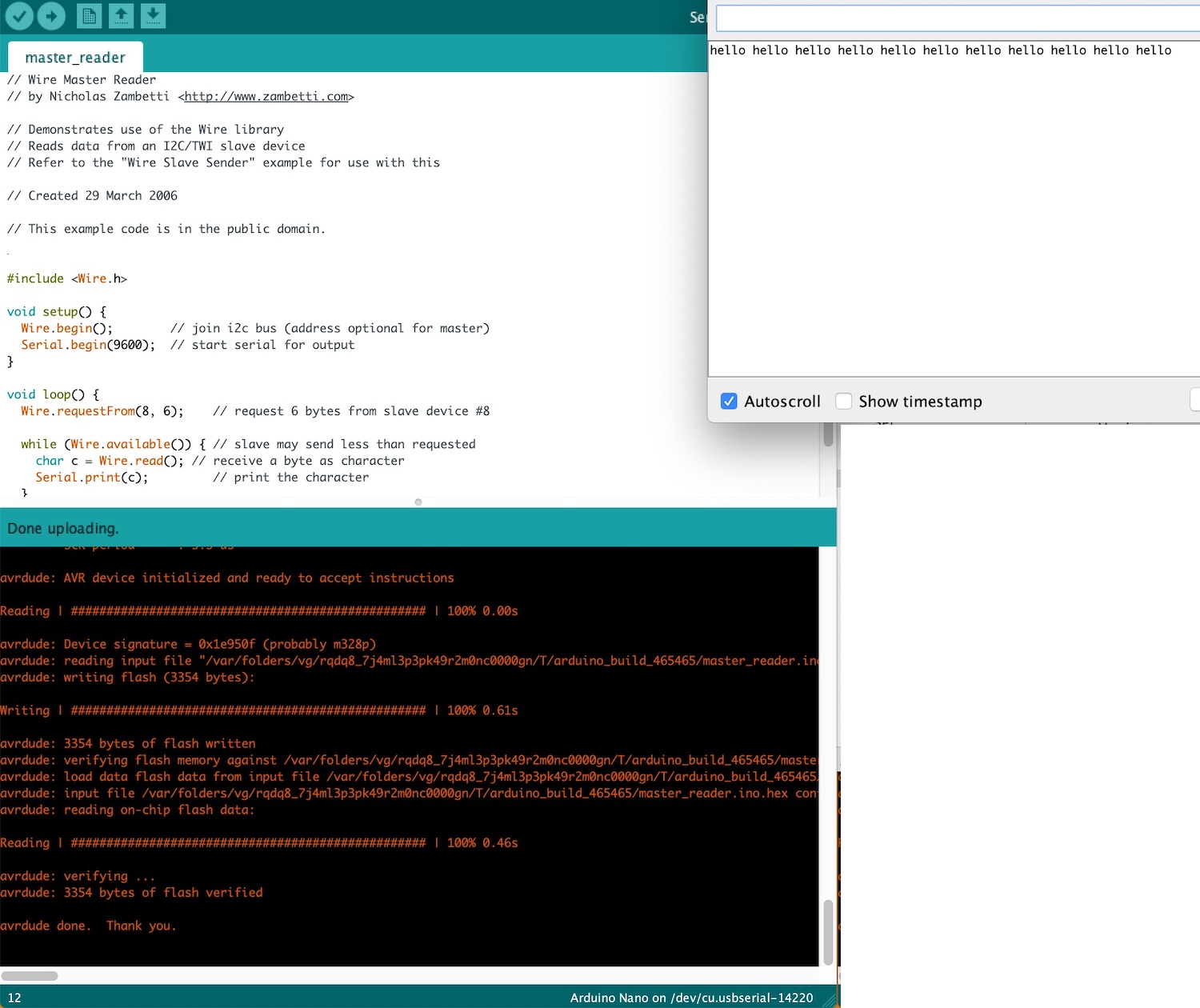
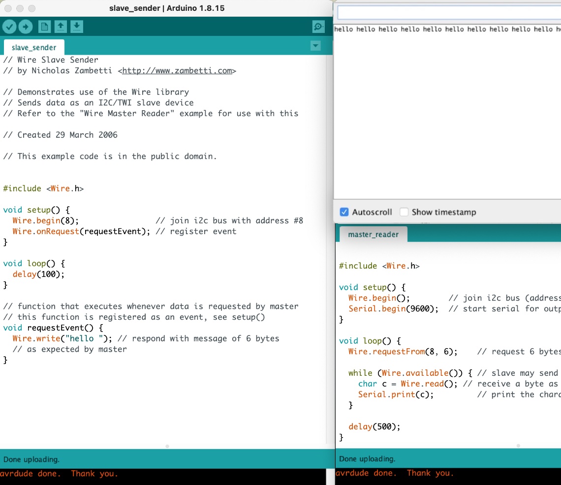
IT worked!! Sending the address between the two boards coming up with 'hello' in the serial monitor.
      // Wire Master Writer
      // by Nicholas Zambetti

      // Demonstrates use of the Wire library
      // Writes data to an I2C/TWI slave device
      // Refer to the "Wire Slave Receiver" example for use with this

      // Created 29 March 2006

      // This example code is in the public domain.


      #include

      void setup() {
        Wire.begin(); // join i2c bus (address optional for master)
      }

      byte x = 0;

      void loop() {
        Wire.beginTransmission(8); // transmit to device #8
        Wire.write("x is ");        // sends five bytes
        Wire.write(x);              // sends one byte
        Wire.endTransmission();    // stop transmitting

        x++;
        delay(500);
      }
      // Wire Master Reader
      // by Nicholas Zambetti

      // Demonstrates use of the Wire library
      // Reads data from an I2C/TWI slave device
      // Refer to the "Wire Slave Sender" example for use with this

      // Created 29 March 2006

      // This example code is in the public domain.


      #include

      void setup() {
        Wire.begin();        // join i2c bus (address optional for master)
        Serial.begin(9600);  // start serial for output
      }

      void loop() {
        Wire.requestFrom(8, 6);    // request 6 bytes from slave device #8

        while (Wire.available()) { // slave may send less than requested
          char c = Wire.read(); // receive a byte as character
          Serial.print(c);         // print the character
        }

        delay(500);
      }
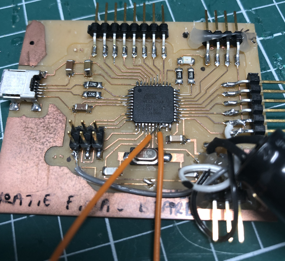
As pointed out I have used Luiz board therefore means I needed to redo this week with a board I had designed myself, so I used my board for my final project which was an edited version of Luiz board. I did have to hack a few pieces onto the pins that I needed as they were two of the pins that were not brought out as I didn't think I was going to need them in the future.
I got a male to male wire cut it in half, stripped the ends and soldered them to the correct pins.
Here are the two boards together, it is a little more manic than the one above as my 'final board' I have to use a programmer to get anything to go onto it which is a pain. But this did work, I did end up having to change the code from above as this didn't work. Please see the .ino file below to see the correct sketch for this outcome as seen below.
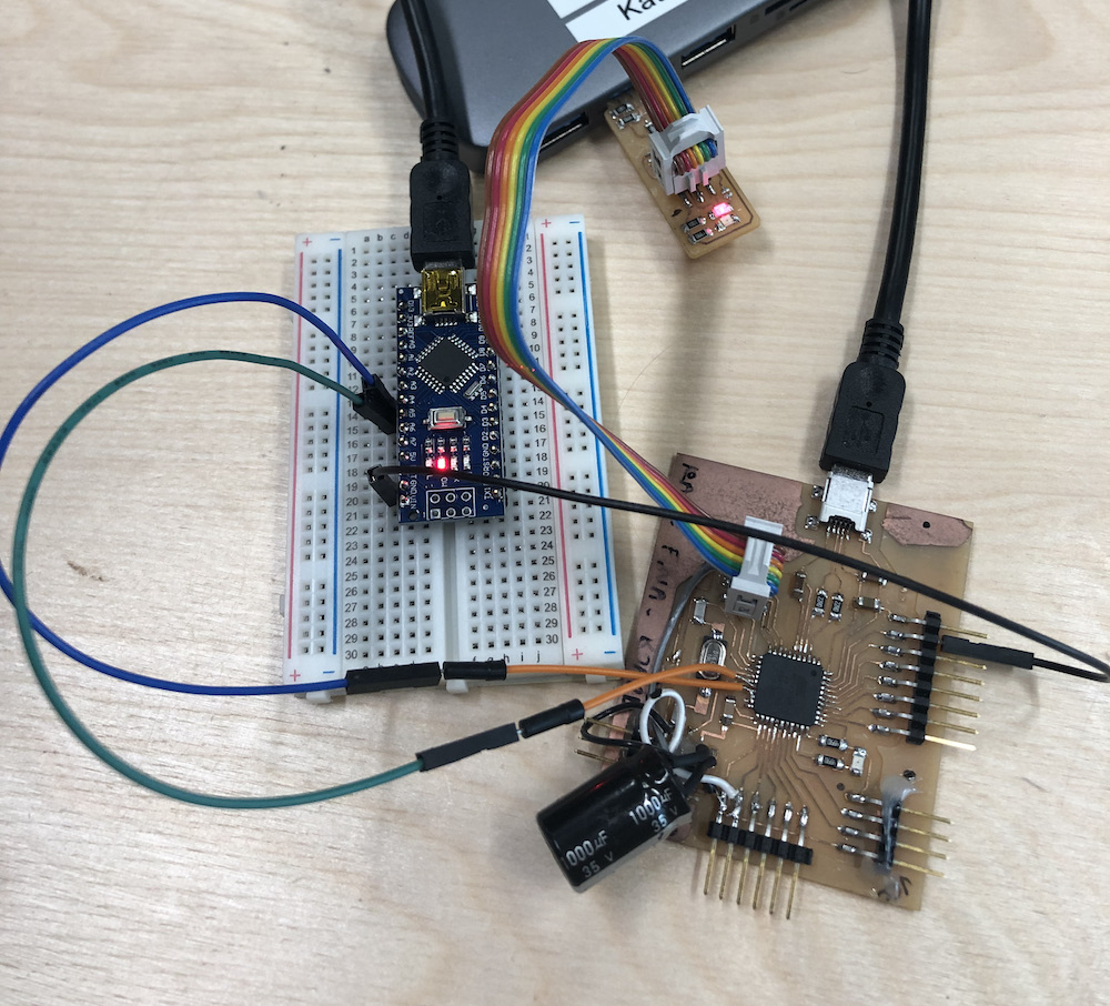

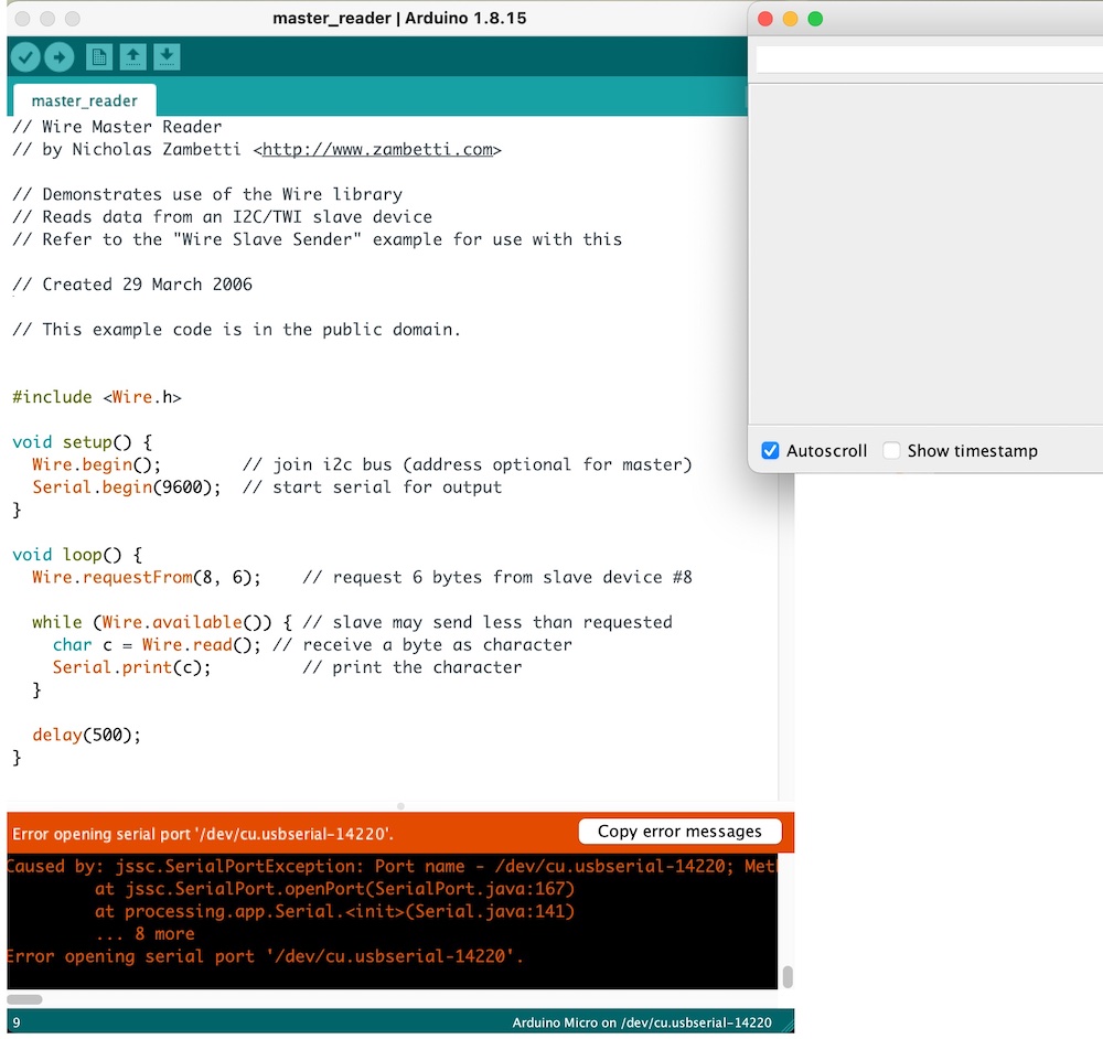
I am so happy this worked as at the beginning I kept getting an error saying that it couldn't find the correct serial port, I resoldered the wires which then worked as seen! woohoo.
These are my traces and outlines for my edited board, if you need Luiz outline and traces click here