Link to Output Devices Group Page
'For most non-portable "desktop" projects, a 5V DC switching power supply is ideal. This small 2 Amp supply is good for a a meter or so of NeoPixel strip.'
Adafruit Battery Power for LED Pixels and Strips Overview
'The recommended 5 Volts is a "nominal" rating... we actually have a little bit of wiggle room here. About 10% above or below this figure works fine. You can see this by measuring the output of a wall adapter with a voltmeter: due to manufacturing variance, the actual output could be anywhere in this range. So anything from about 4.5 to 5.5 Volts is safe for these LEDs and 6V is the 'rated absolute maximum'. Any higher and they'll burn out quickly. Any less and the colors will appear muddy and brown.'
What ada fruit suggest on their website:
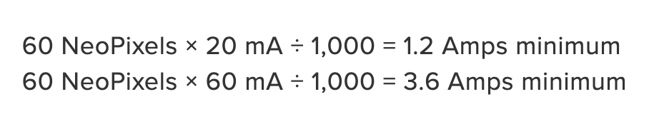
'To estimate power supply needs, multiply the number of pixels by 20, then divide the result by 1,000 for the “rule of thumb” power supply rating in Amps. Or use 60 (instead of 20) if you want to guarantee an absolute margin of safety for all situations. For example:'
I have 45 neo pixels:
  45 (neo pixels) x 20 mA / 1,000 = 0.9 Amps minimum

  45 (neo pixels) x 60 mA / 1,000 = 2.7 Amps minimum
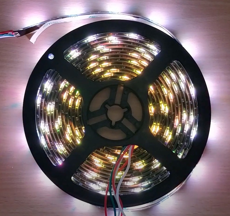
I have been watching these videos online about neopixels and how they work with FastLED which is a way to make the patterns. The link to the videos are here and whne watching the guy shows us how when you light up a long string of neopixels with not enough power the last few loops go yellow when they should be bright white. This is because they are not recieving the correct amount of power when plugged in, to avoid this you can add more power every 1 meter he says in his video but best to double check
Here is the photo of the neopixels going from bright white to yellow.
Neopixles have changed the way LEDs now work, you can have 1,000's of neopixels all running on the same pin (this is my plan). This means that compared to previous LEDs you would have to have a pin for each led which gets very complicated with wires and chips all over the place. Neopixels also allow you to have full-colour LED which means you have red, blue and green all in one very small very bright neopixel.
This link from Adafruit has been the way I have learnt all about neopixels and how they work.
Single in/ out = date_pin in arduino
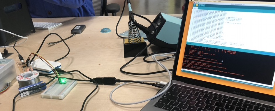
I used my board from week 11.
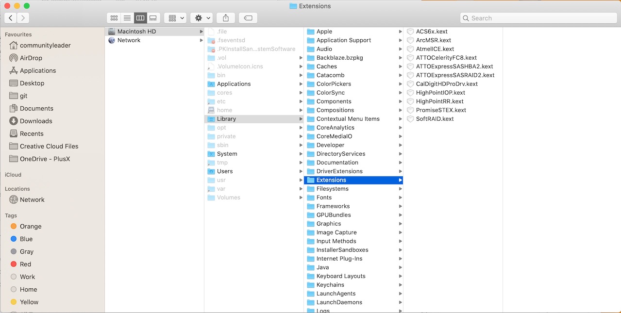
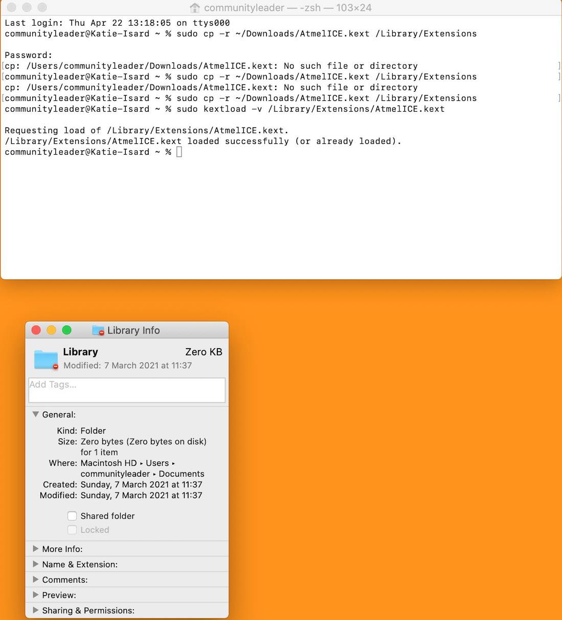
Followed this link link that Andrew sent me so that I can use the Atmel ICE programmer on my Mac.
I was having issues as I couldn't get open my 'Library/ Extension' folder which it is said the download needs to be saved in.
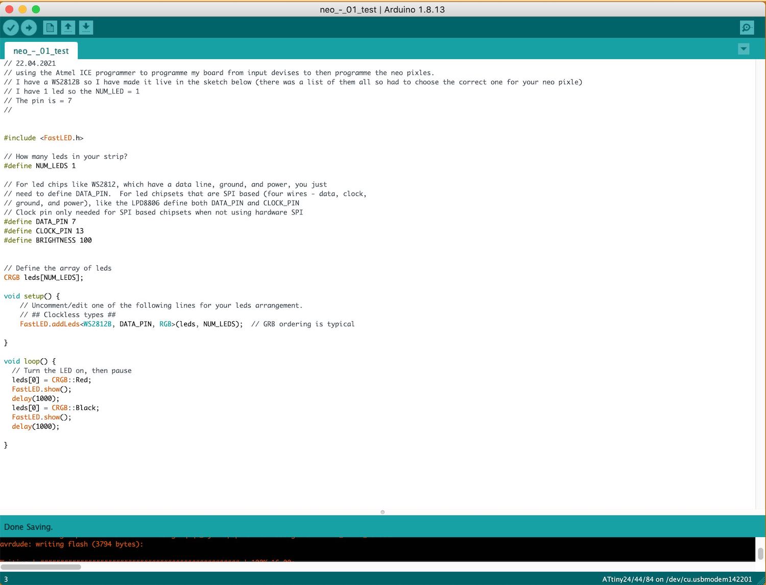
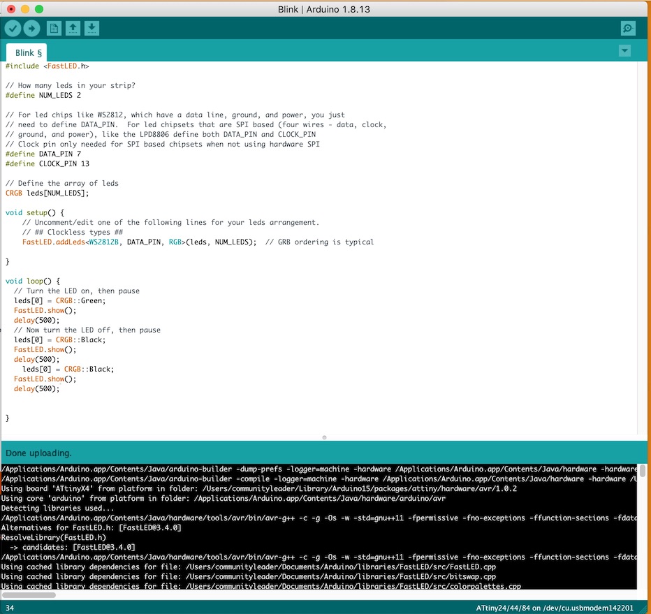
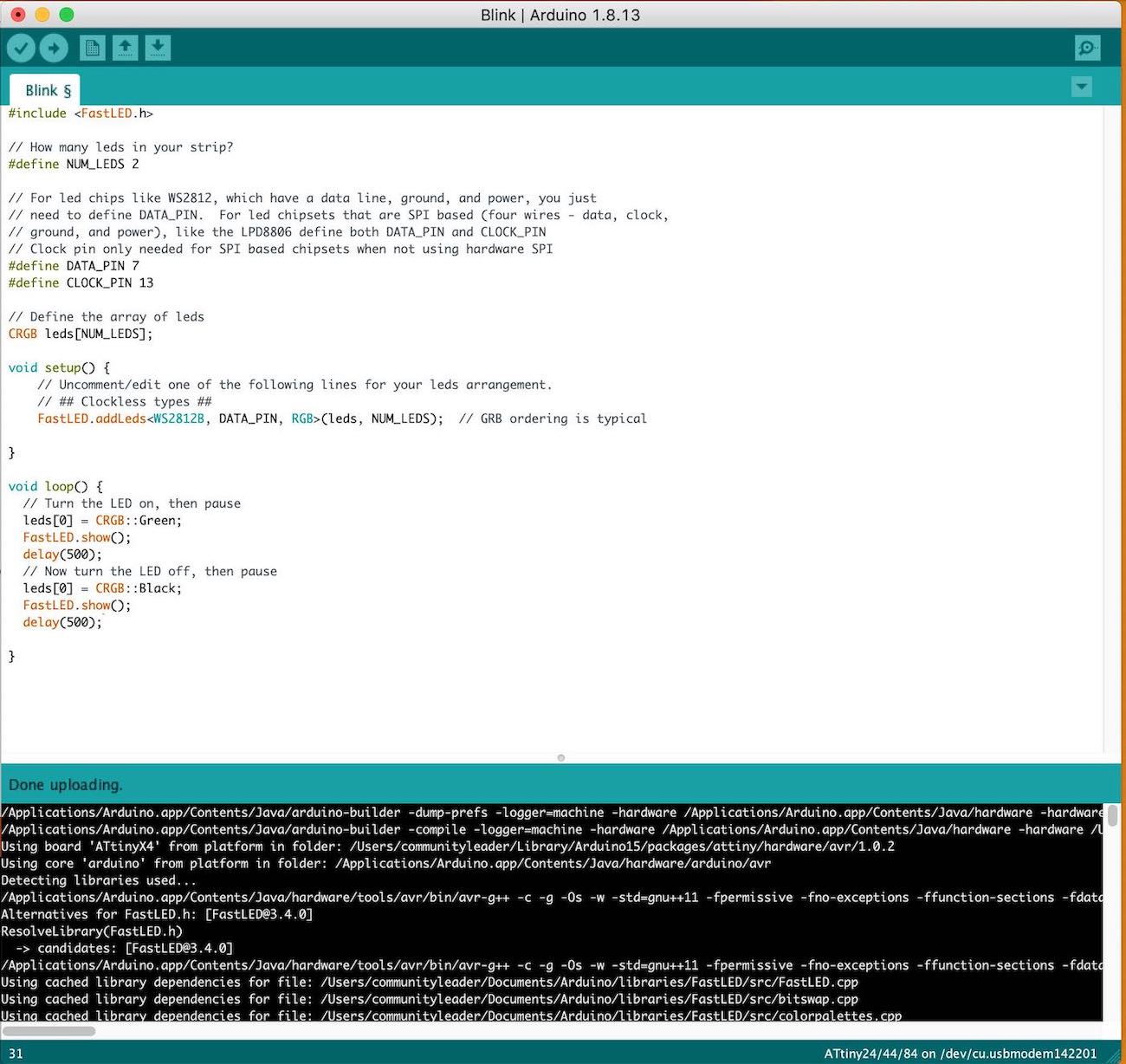
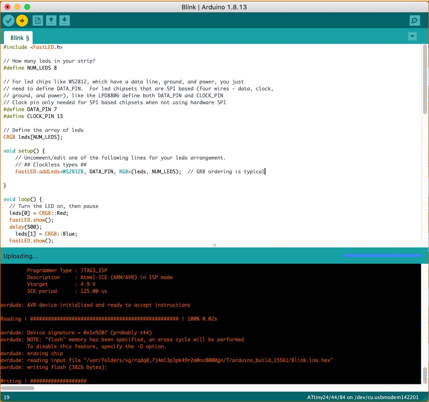
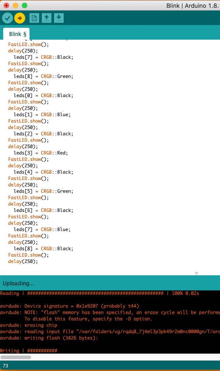
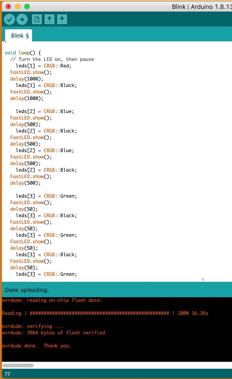
Using the Blink sketch from Fastled
Having so much fun playing around with this sketch.
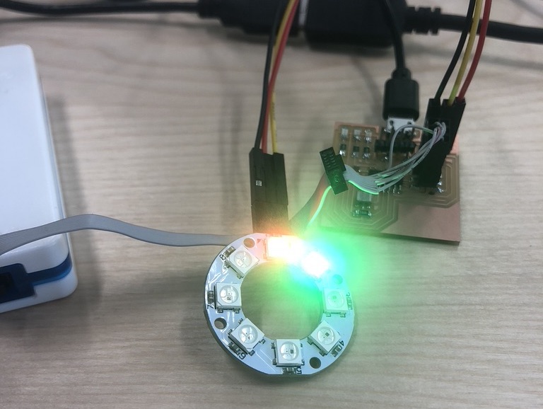
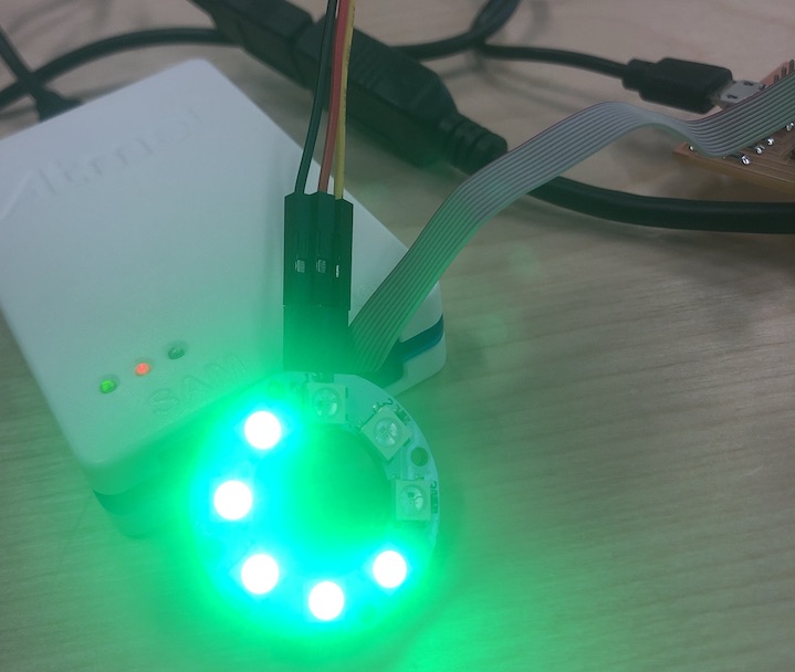
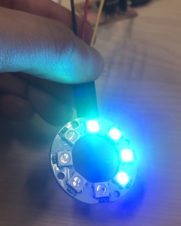
First I tried it just with the one led lighting up, then Andrew said that because I was using Neo pixels they are made to have many in one row so I started to use neopixels in a circle.
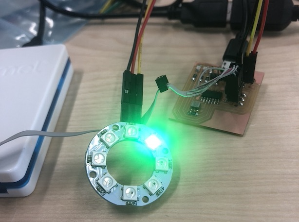
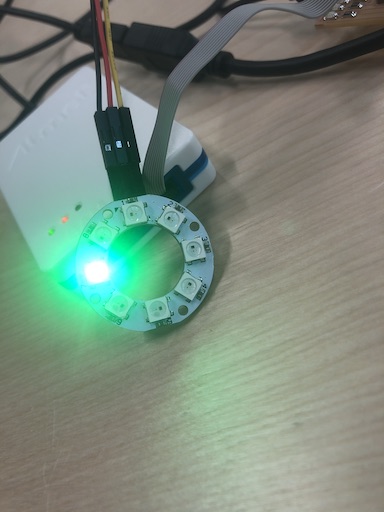
The only odd thing is that it is meant to be red and it is lighting up green?
I then moved into using neopixels in a circle to have a little more fun with as Andrew suggested.
I tried to upload this sketch and it was working but the 2nd neopixel was still lighting up green which was a little weird.
I then turned the 2nd LED off just by making it black in the sketch and this work.
I thought I should ask Jonny what to do as this wasn't correct in the sketch when I was uploading it. But for some reason he came along I changed a few things and now it worked.
I then started to just play around to see what other patterns I could get...
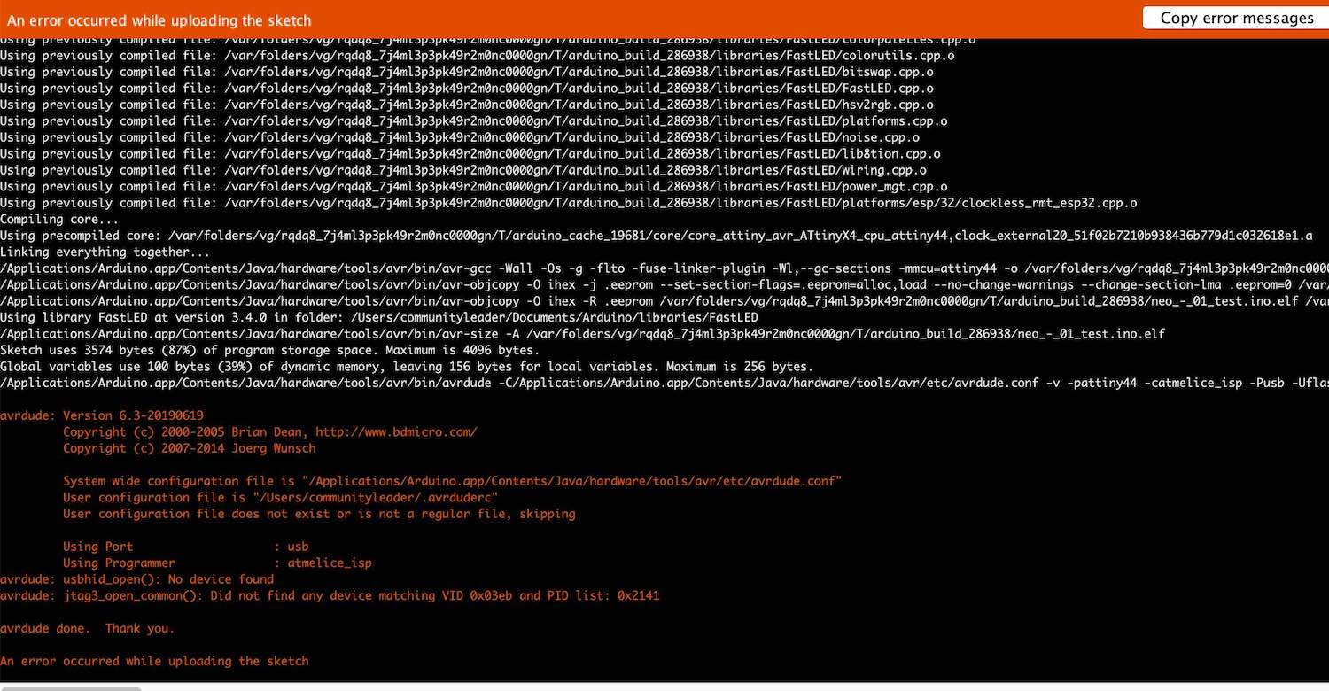
It kept coming up with this error so I just wobbled around the wire to all the devises and redid it, it worked very well so this helped with the uploading of the new programme.
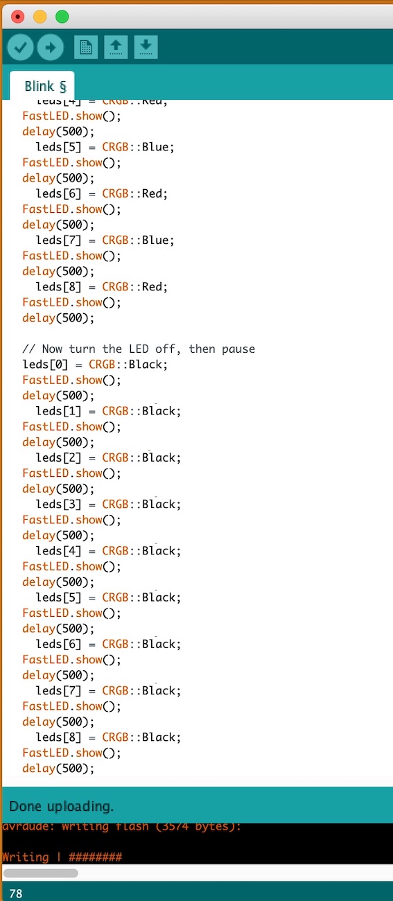
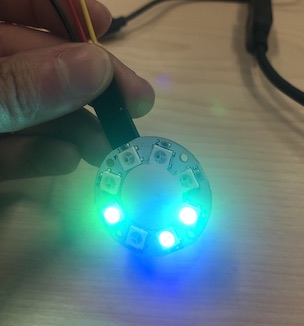
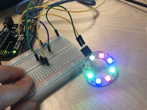
I made it so that each pixel would light up and then turn off and then the next one in the line would do the something. It was very fun getting to grips with each part I can play about.
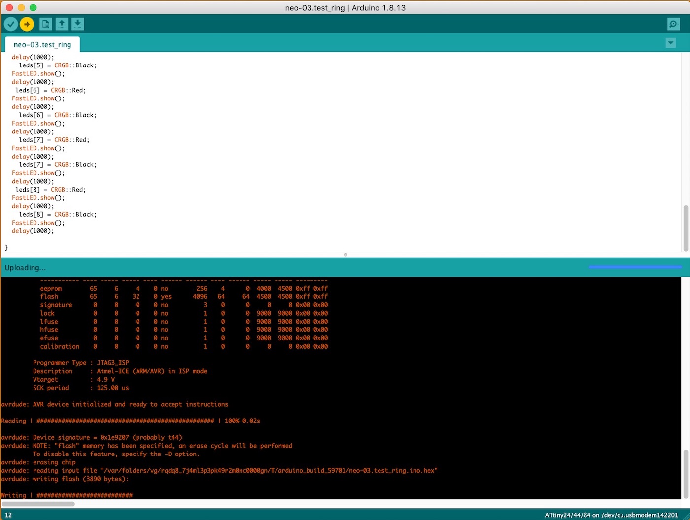
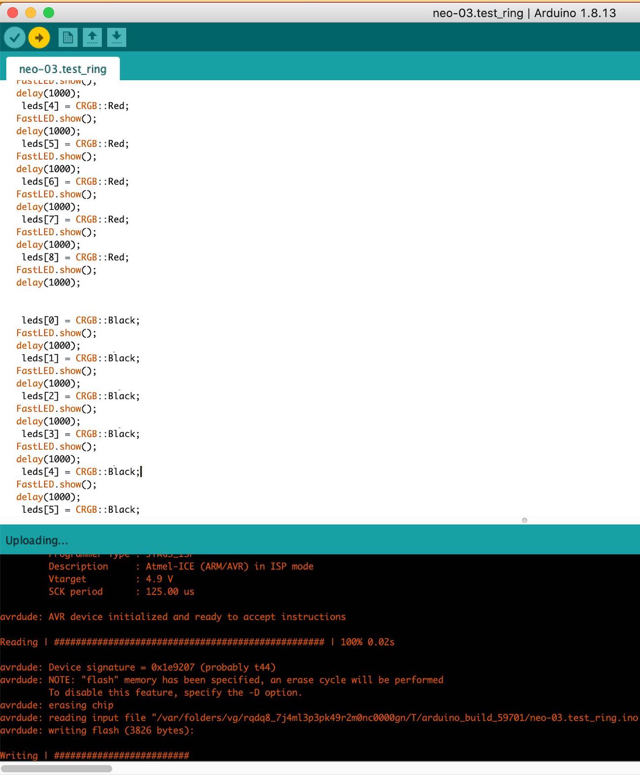
Made it so that the it would make a whole circle gradually going up and then it would go down turning all the pixels off gradually.
Also changed the delay from (1000) to (500) to make it go quicker which was very cool, I then thought as they have placed the colours in could I change them...
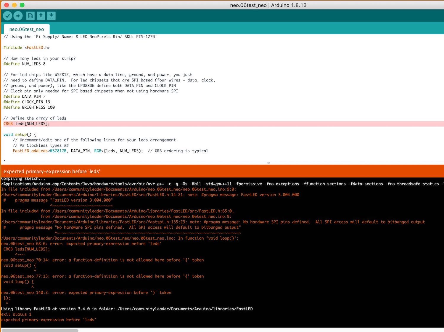
I then changed the colours around but this error message came up...
I had copied a few sketched into the same sketch so it think it was getting very confused into what It was meant to be doing.
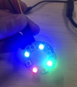
I made it so that the first loop they would got from blue and green (red) and then turn off to black all going 500
It wasn't working kept coming with an error saying it couldn't find the board so I unplugged it and went for lunch, I then came back plugged it back in and it worked! Woohoo
I then changed them all to be 250 delays to make it quicker which was very cool, I'm having a lot of fun!
I changed the design and made is very very random it was very fun and can't believe this is working!
I want to make something that is truly a pattern and that I know what it is doing rather than playing around with some flashing lights.
I did one at a time to see if this was working for me, and it did work which was great but still think there was something else I could be doing to make sure they were flashing all at the same time. The code is going to be long and hard later on when I have 60 of these neopixels to work with.
      'Sketch too big; see for tips on reducing it.

       text section exceeds available space in board

       Error compiling for board ATtiny24/44/84.'
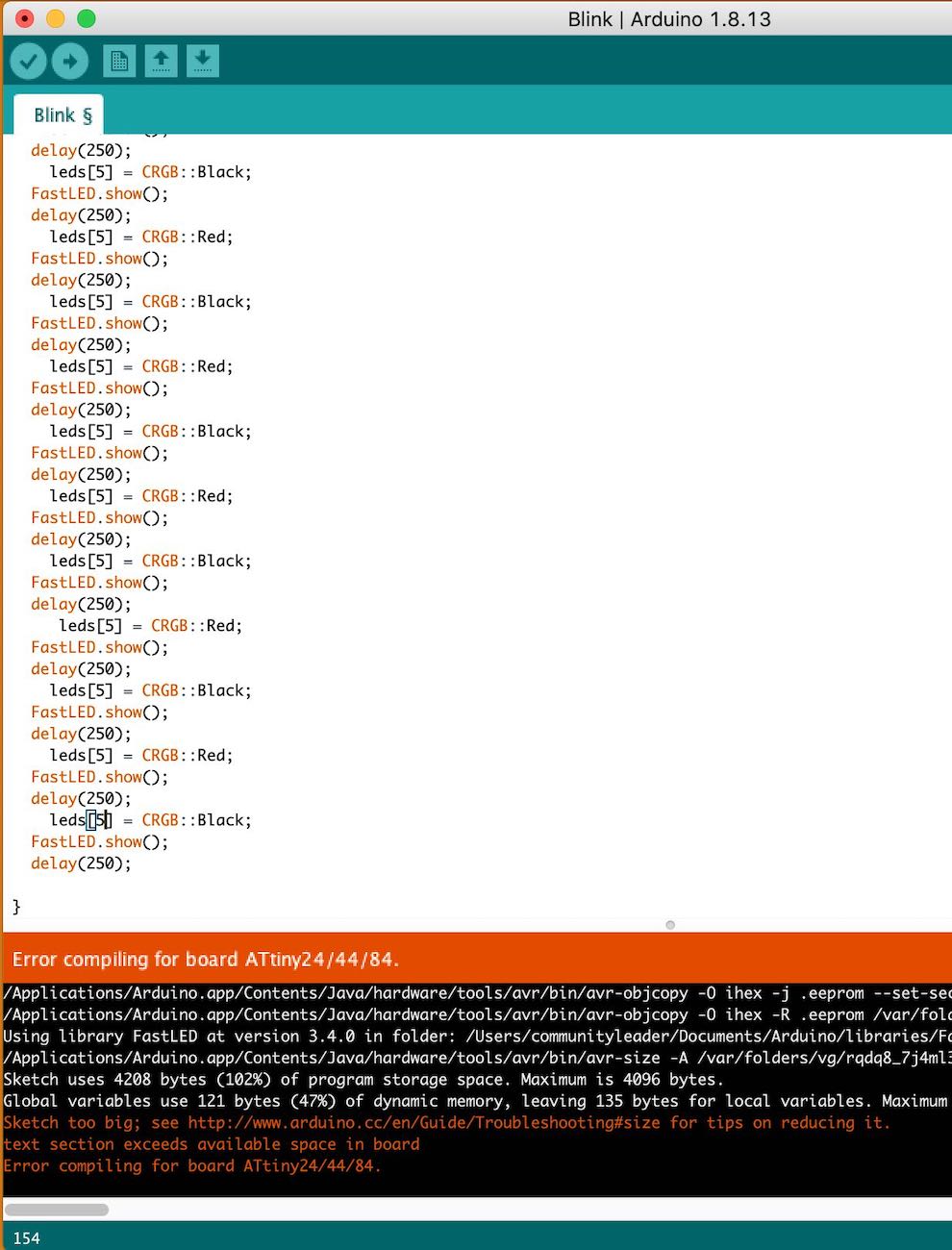
I had this issue earlier when I can trying to add a different sketch:
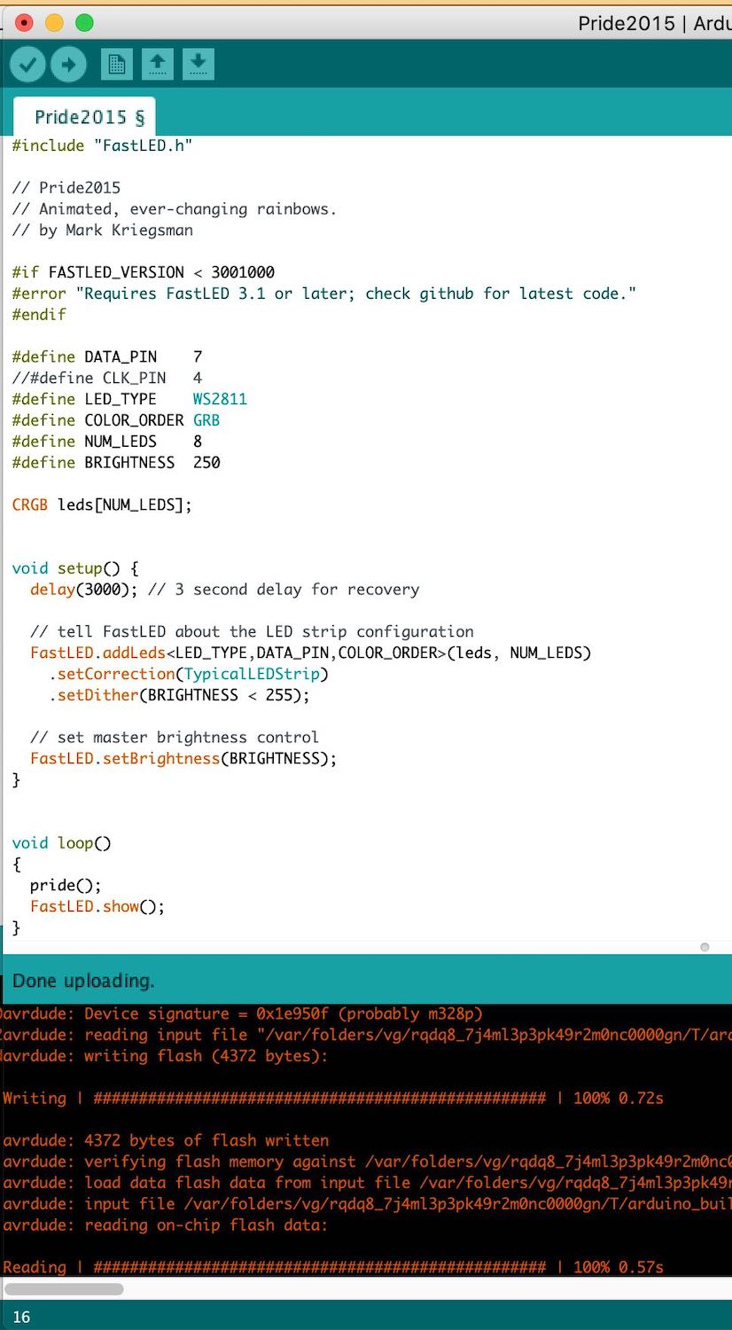
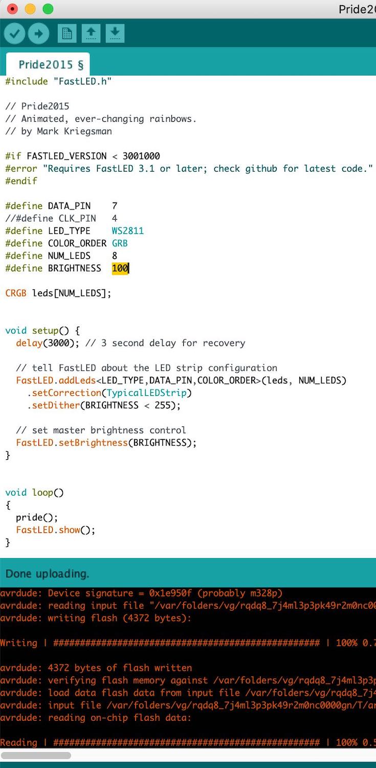
Trying out the Pride2015 sketch in Fastled
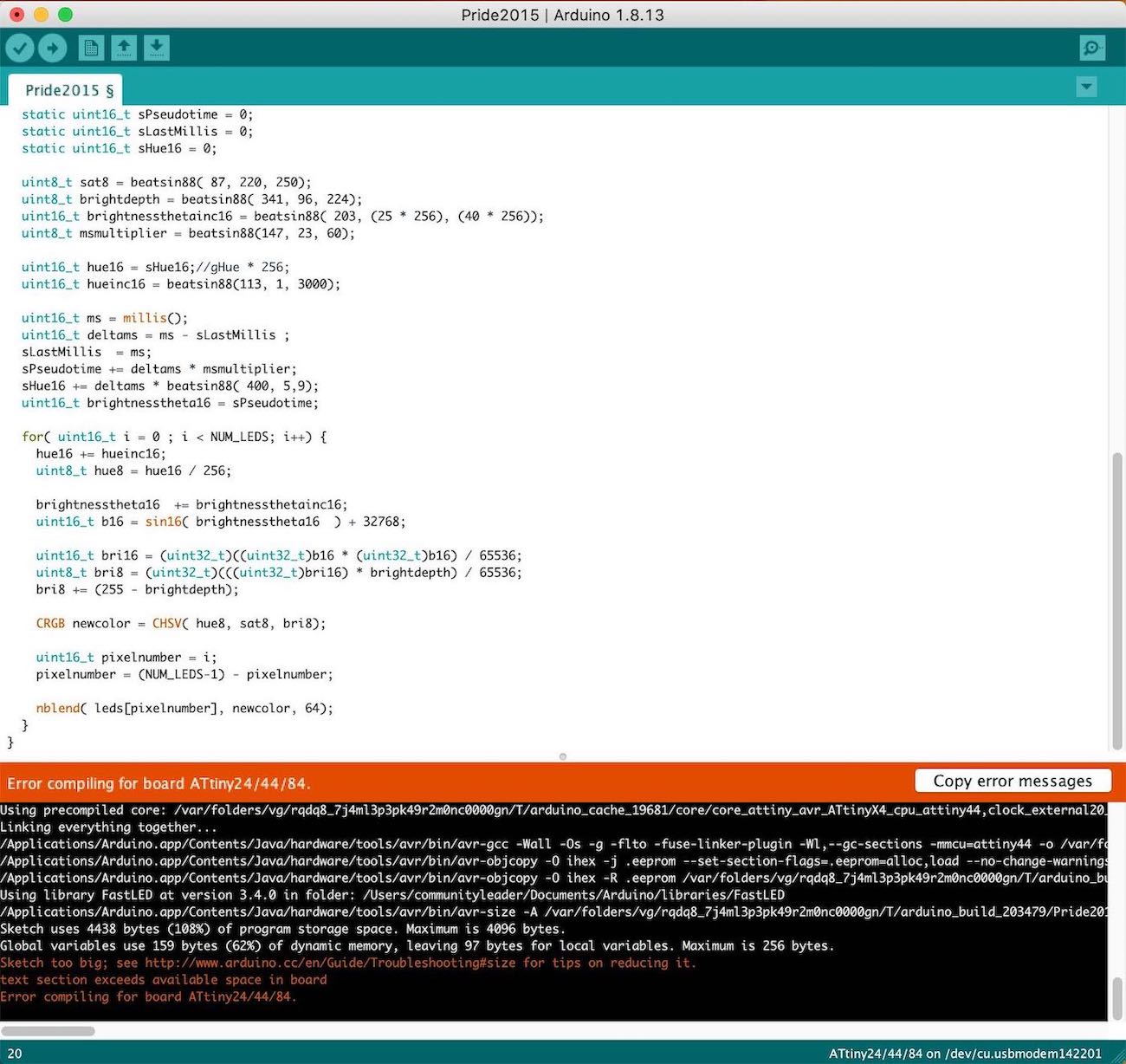
      'Sketch uses 4438 bytes (108%) of program storage space. Maximum is 4096 bytes.
       Global variables use 159 bytes (62%) of dynamic memory, leaving 97 bytes for local variables. Maximum is 256 bytes.
       Sketch too big; see http://www.arduino.cc/en/Guide/Troubleshooting#size for tips on reducing it.        text section
       exceeds available space in board

       Error compiling for board ATtiny24/44/84.'
My ATtiny 44 has 4096 bytes whereas this sketch need 4438 bytes so it is 108% too much for my chip. I need to upgrade to another chip such as the 1614.
I moved onto using an uno because the sizes of my sketches were getting too large for my chip which was a ATtiny44. I think I am going to move to a 1614 chip so that I can keep trying bit out but for now I am going to understand how to use and programme neopixels so that I can progress with my final project right now.
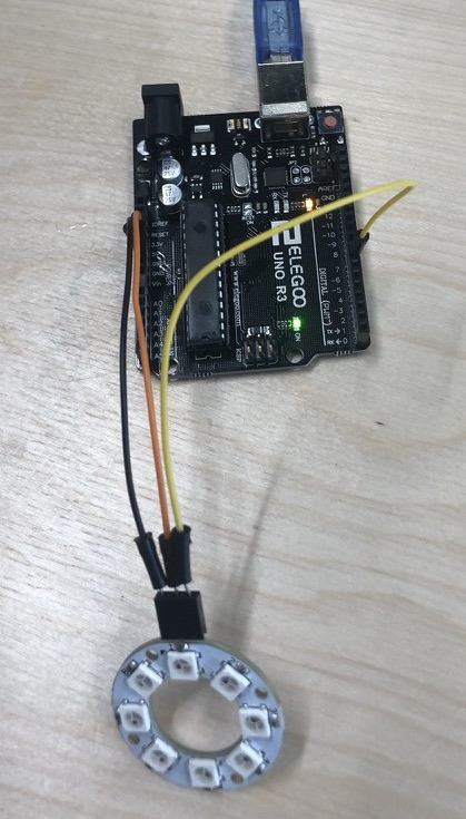
Once setting everything up I decided to use an arduino so that it could hold more storage.
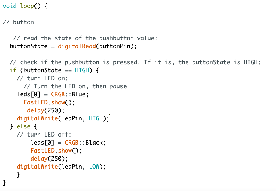
I then thought I should try and make it so that I can control the neopixels when I press an input such as a button. So I got an arduino sketch of a button and made this work with the led on the board.
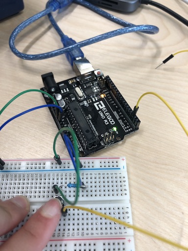
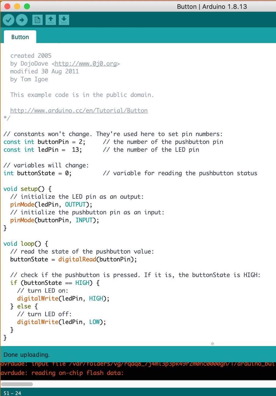
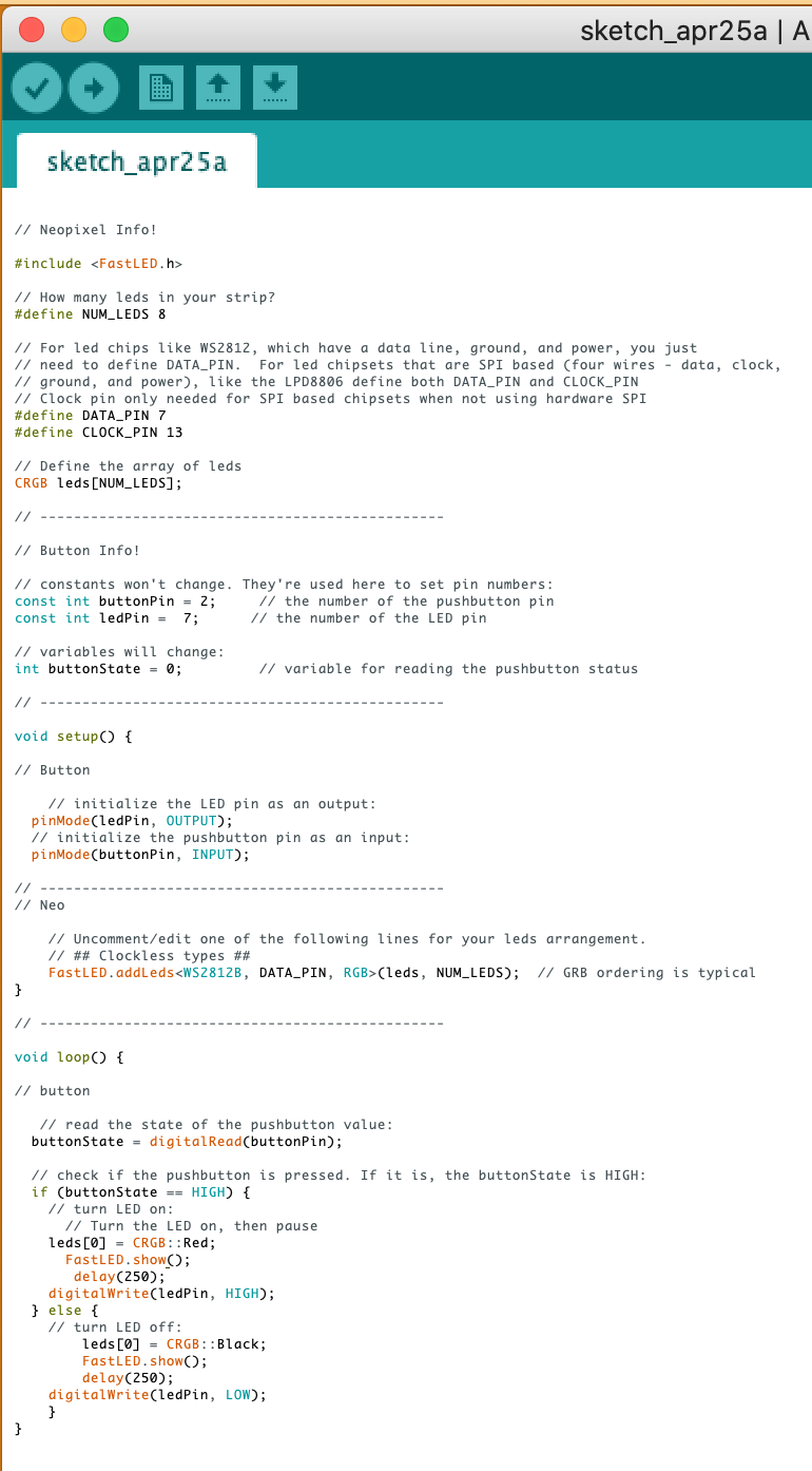
As this was working I then decided to add the neopixels to see if this would work, by hacking the two sketches together to see if by doing this it would turn the neopixels on with the button.
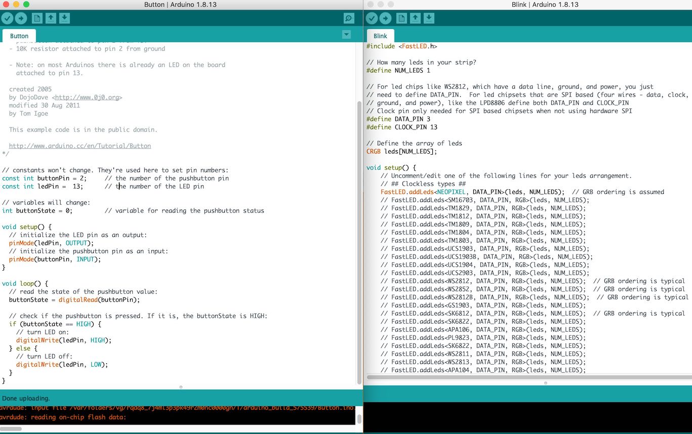
Here is both the button sketch (left) and the neopixel sketch (right). I know both of these work when using the arduino so if I now put them together does this then work.
This did work, I first realised I didn't have the pin correct, then the cord was connected to the wrong pin on the neopixels and then I realised I needed to give it power.
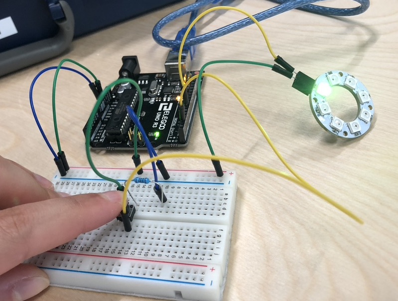
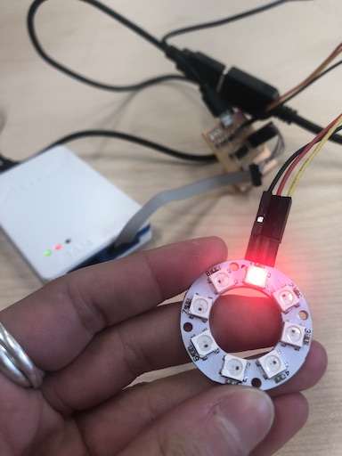
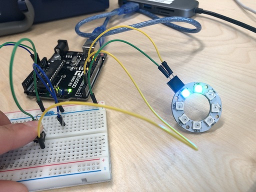
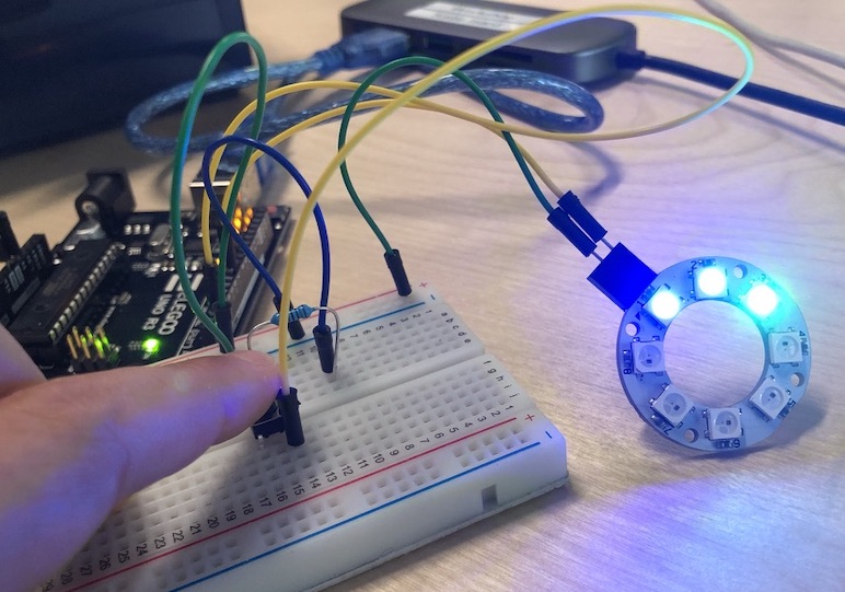
I was then trying to get it so that I was controlling the neopixels BUT when I turned it on:
This was the first one as shown above and the 1st neopixels is turned on which is correct.
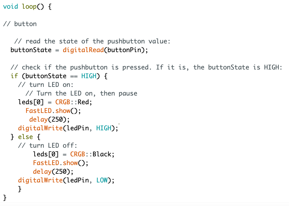
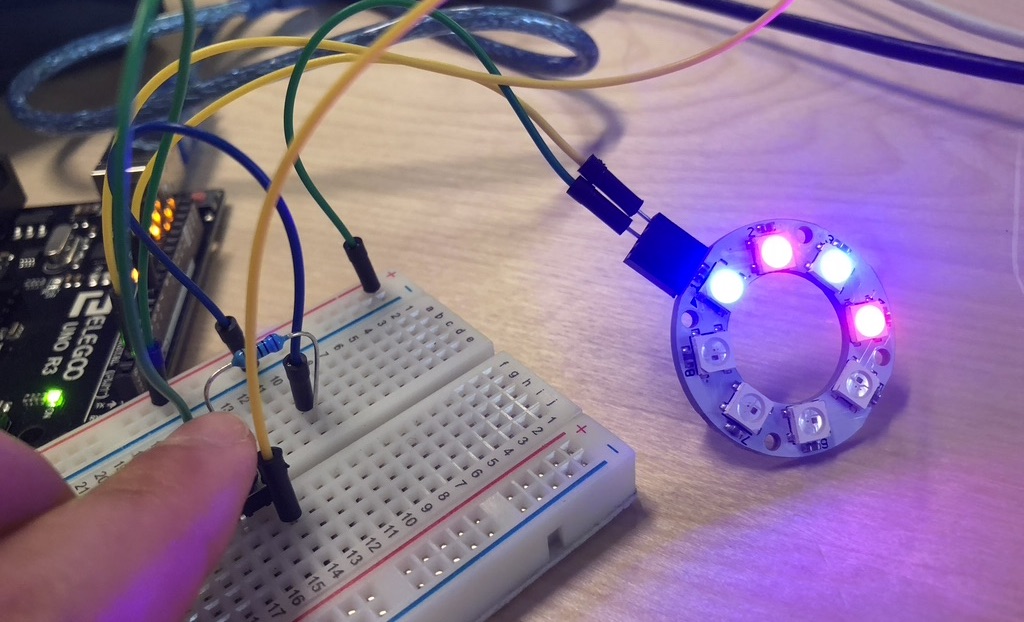
Turning the neopixels blue rather than green (red) it was still turning on the 2nd neopixel which was very weird and annoying.
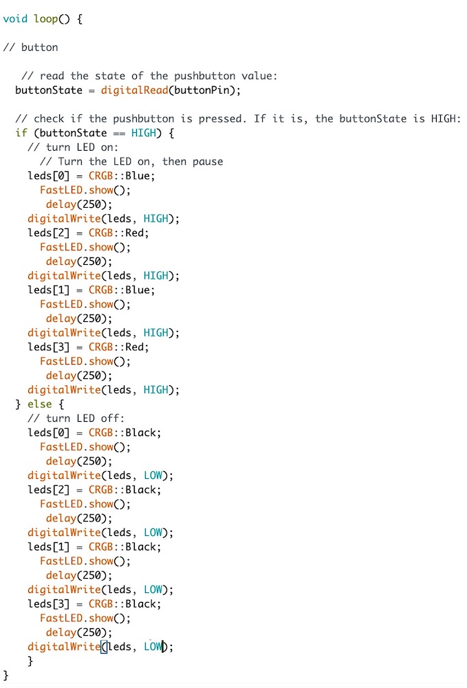
I then realised that the button sketch still had its 'ledPin' written into the sketch so I went back over the sketch and got rid of the 'ledPin' and replaced it with 'leds' which is written in the blink sketch.
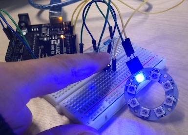
Now that this worked I thought I could play around bit just seeing what I can do and how they work together.
It worked well, making the neopixels light up in the correct order when I pressed the button
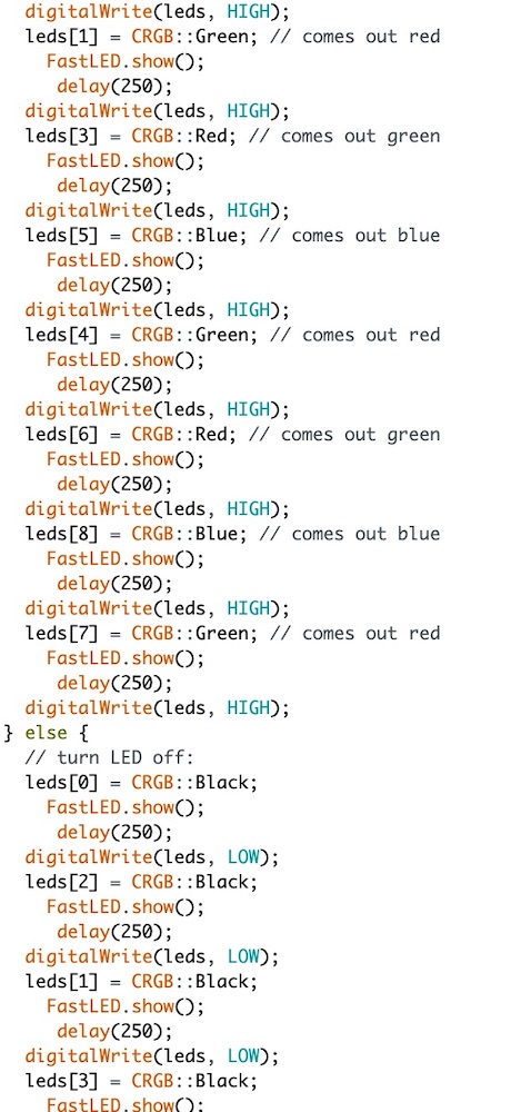
My neopixels are coming out differently red = green/ green = red/ blue = blue -- the reason for this is because some are set up to be RGB and some are set up to be GRB so I think mine is GRB rather than RGB
I googled it and this was the answer which other people had been having issues with - reddit
Just playing around to see the patterns I can make... very fun and instant which is always great.
Instructables link to Ultrasonic Sensor
Going back to wk11 I followed a tutorial that I had followed then to get it to work.
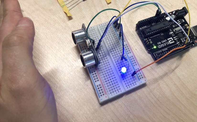
I tried to attach the ultrasonic sensor and the neopixel to connect but for some reason with my previous sketch and the sensor sketch it just wouldn't come together.
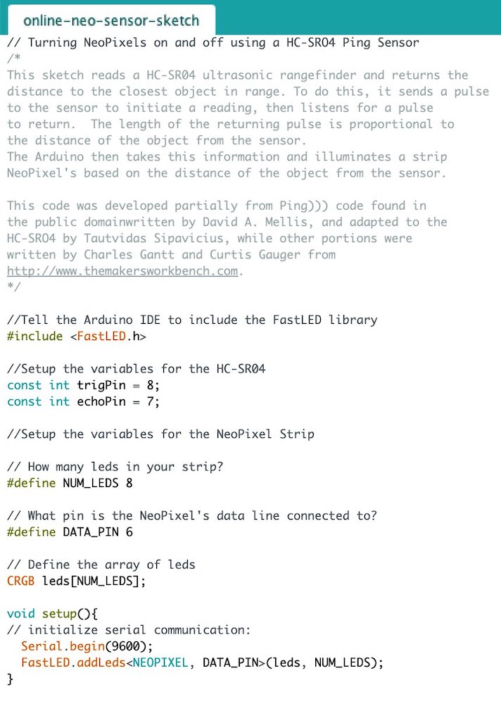
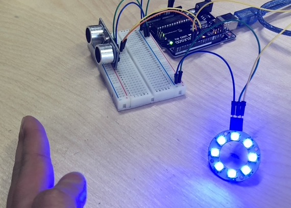
Instead I went online to see if I could follow a tutorial: makerworkbench tutorial link
This was a very very good one, explaining exactly what to write and why you are writing this which really really helped me.
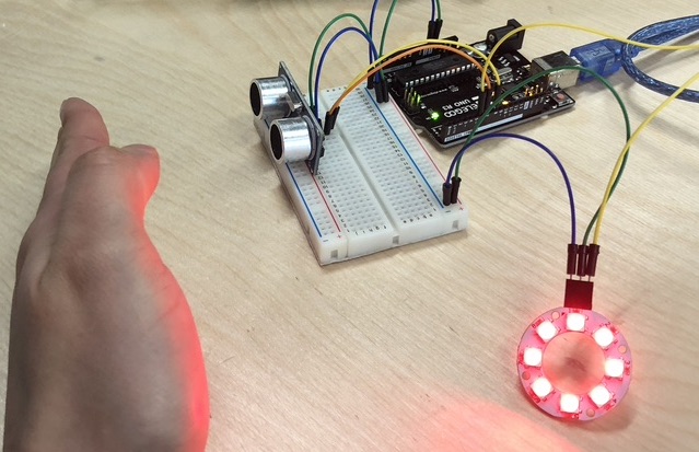
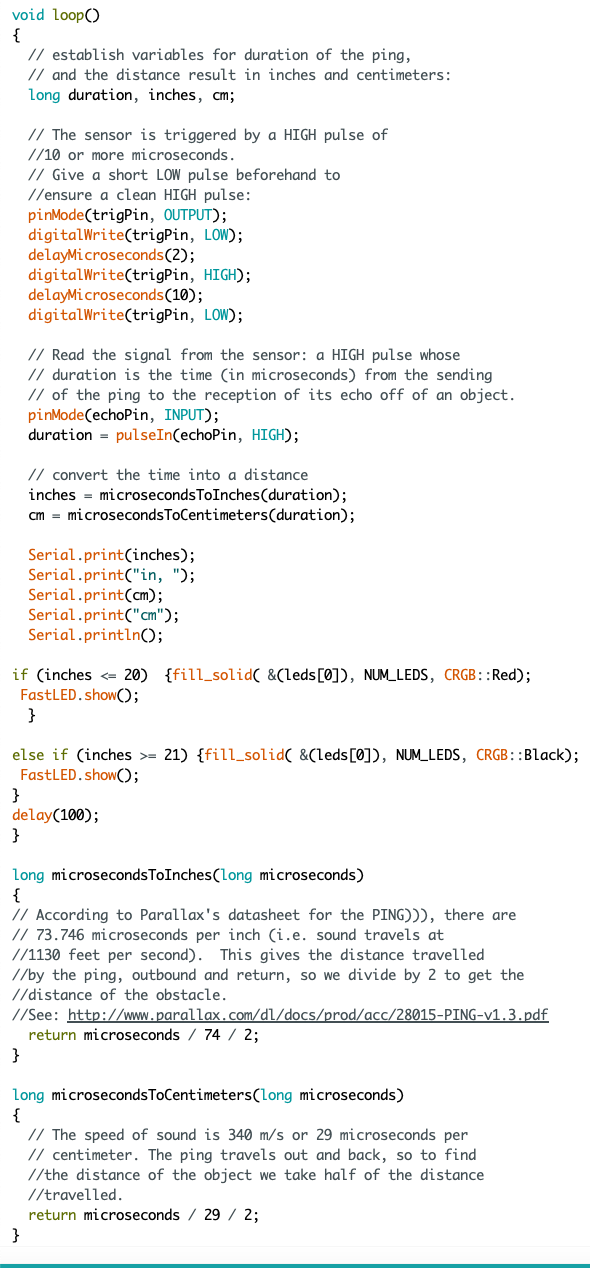
I then changed it so that instead of black it was blue when nothing was in front of the sensor.
I need to learn more about 'if' and 'if else' in arduino!!
So it worked before but when I want to add more to it, it just doesn't accept it. I'm very confused and at this point rather tired.
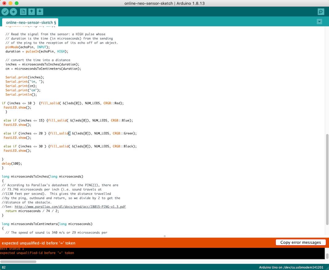
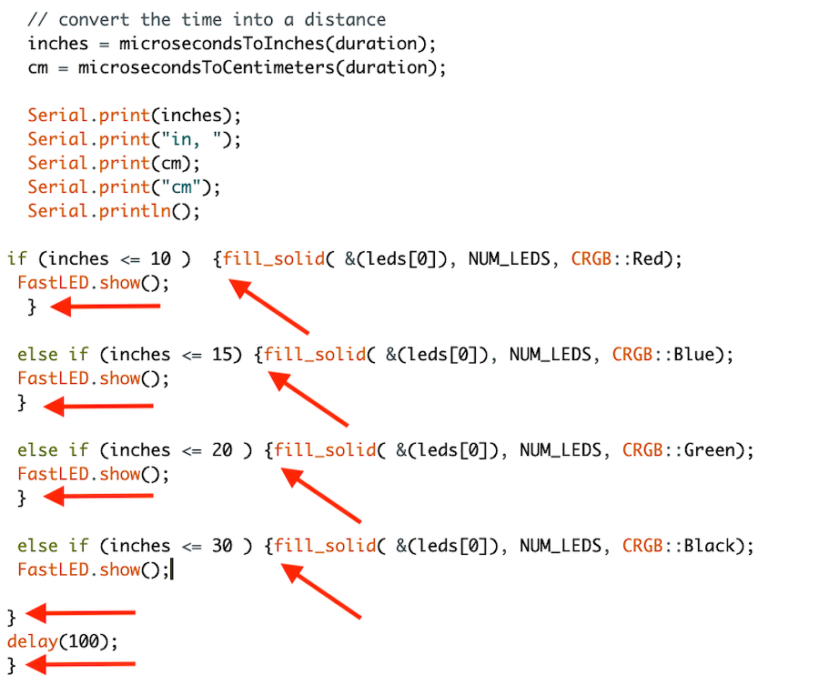
Andrew then noticed that I actually didn't have enough brackets, so when Arduino says ‘not declared in this scope' it probably means that I haven't added a bracket somewhere as I can declare something inside loop but I need to make sure I have placed the { } brackets correctly as shown bellow.

This was one of the Arduino sketchs which I made to get the FastLED to move the colours around the circle of neo pixels. It was great fun to get this to work, I had so much fun seeing it work straight away!
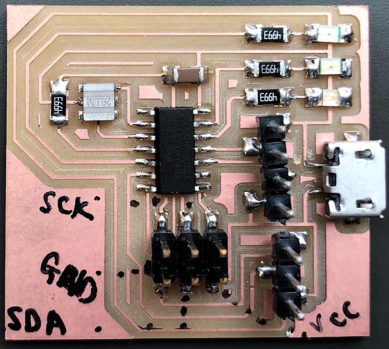
In week 14 I made a board by Luiz which I then altered so that I could use it for mt final project. This is the final board with the large capacitor for the neopixels as I am using 45 in my final project.
Because the board has a mini USB it means that I dont need to have a programmer to upload sketches which is a really helpful part to this chip to have for me.
I used my board from wk11 to do the beginning part - later on I use a new board with a 32U4 in it to allow for the amount of storage I need to run these programmes.