Using a PIR Sensor with Arduino
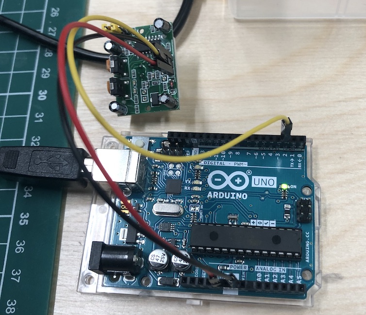
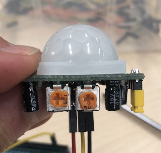
I first tried out the HC-SR501 sensor which detects motion:
I used this to help me understand what circuit I needed to make the sensor, also to see if this is the best sensor for me.
I started by following this tutorial online of someone else who had done the:
It worked which was great!! It is detecting when I am moving closer and future away which it just want I needed.
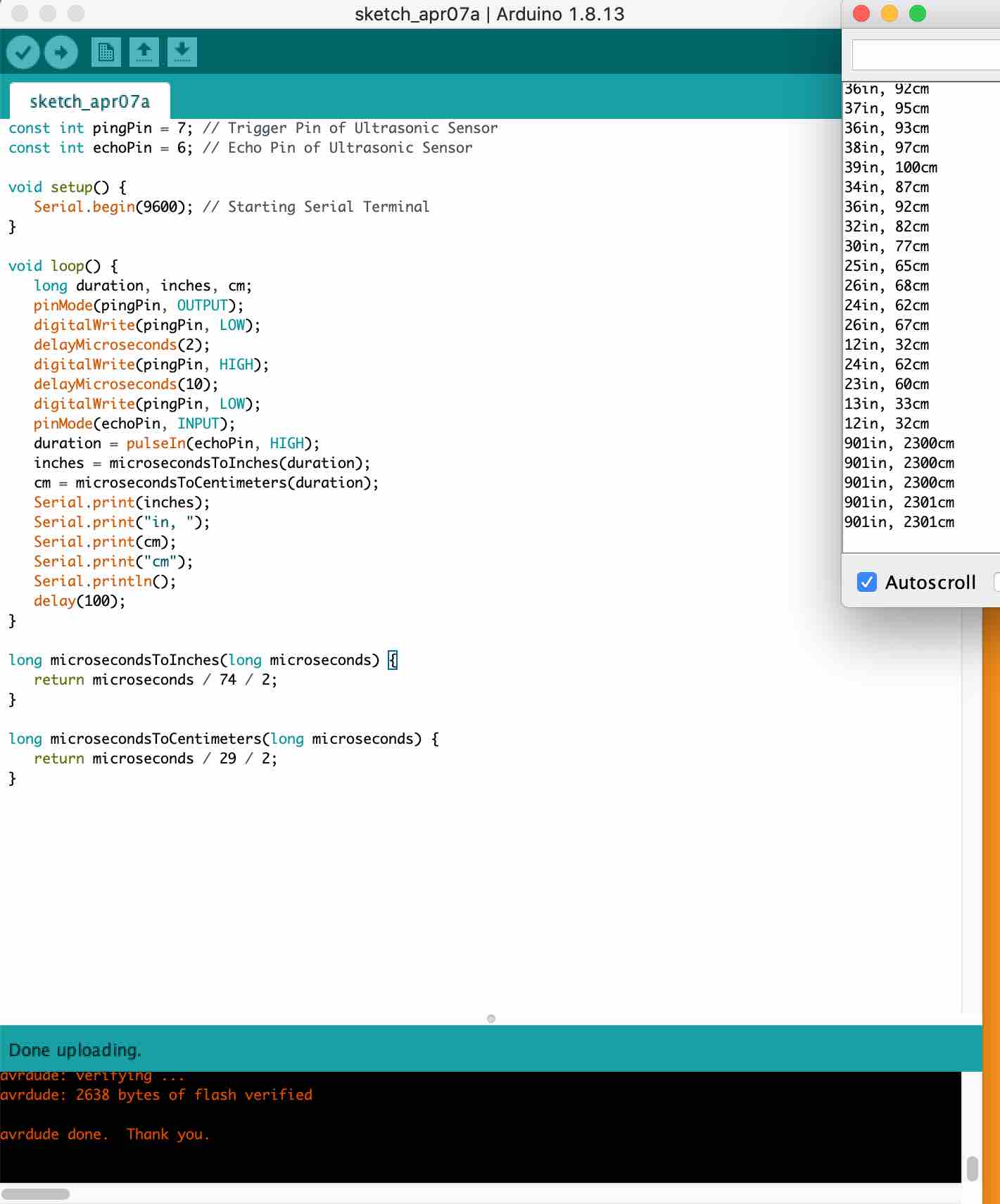
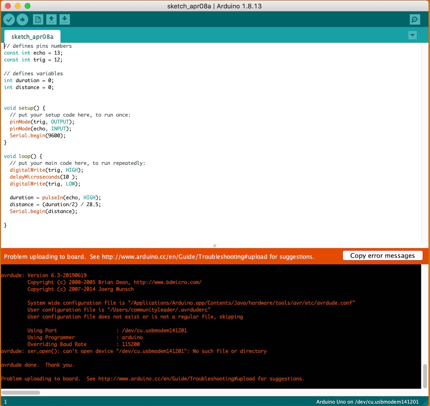
This is the error that kept coming up what ever I did and I just couldn't figure out why. I tried a different USB whole, checked my wires, tried a new dongle just everything and it wasn't working. I then came back a few minutes later as I had cooled off and it worked but no idea why?!
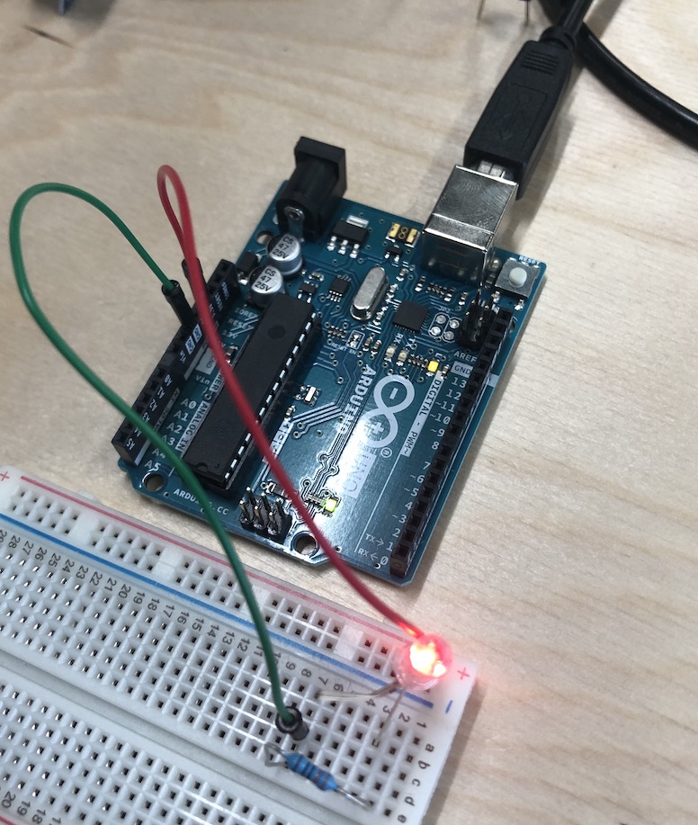
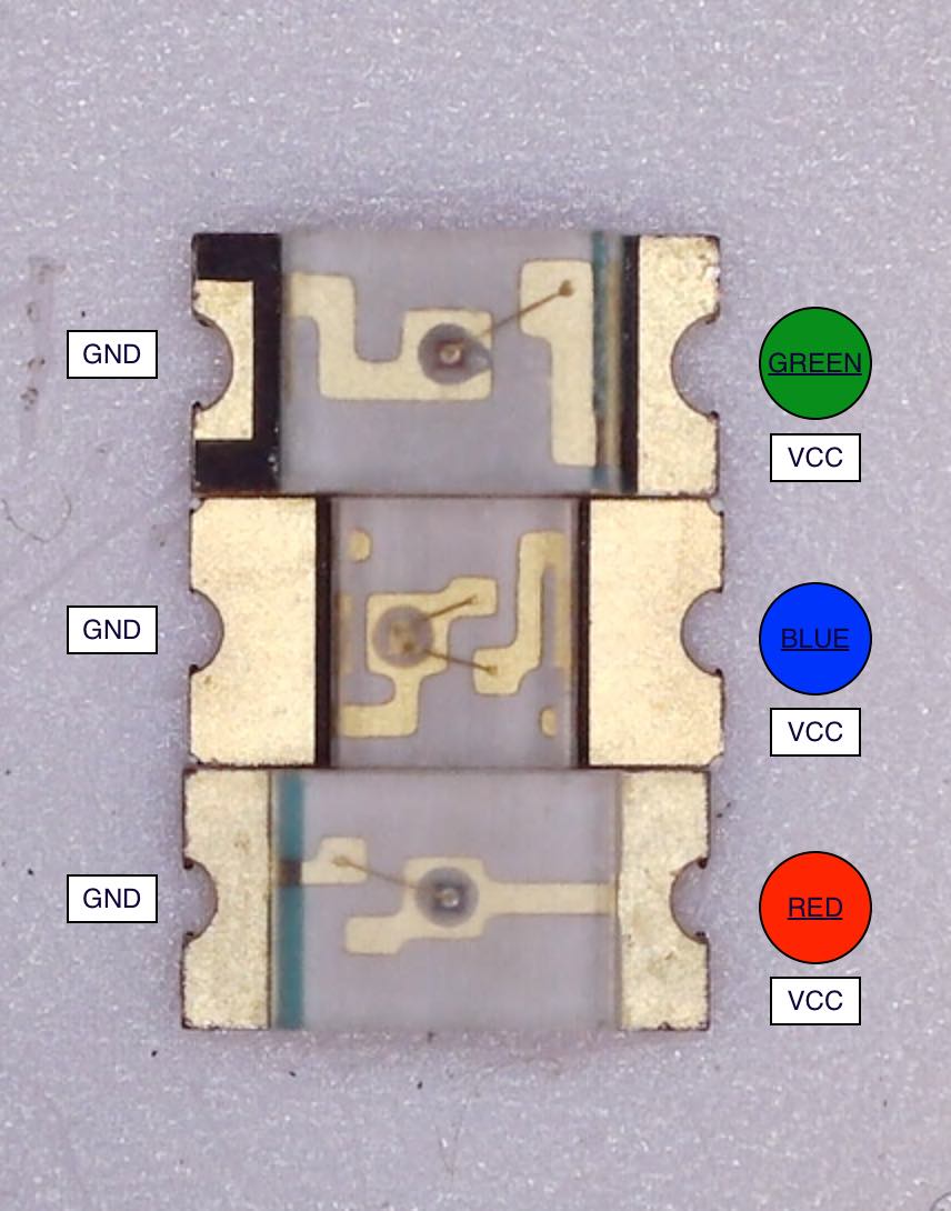
I then thought I could add an LED which would show me when I get a certain distance it would then light up. This in the pinout for an RGB LED:

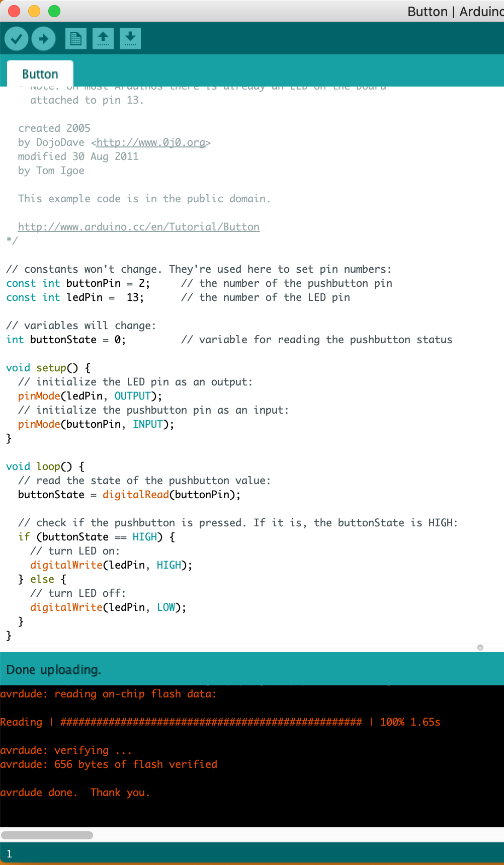
I tried many different types of tutorials for this to work, I first watched this tutorial which didn't come up correctly when I made it go through, it kept saying there was an error.
I then tried this tutorial but this didn't work either. I was starting to get frustrated when Jonny said I may have blown the LED is he gave me a new one and connected it to the board just to double check it worked which it did!!
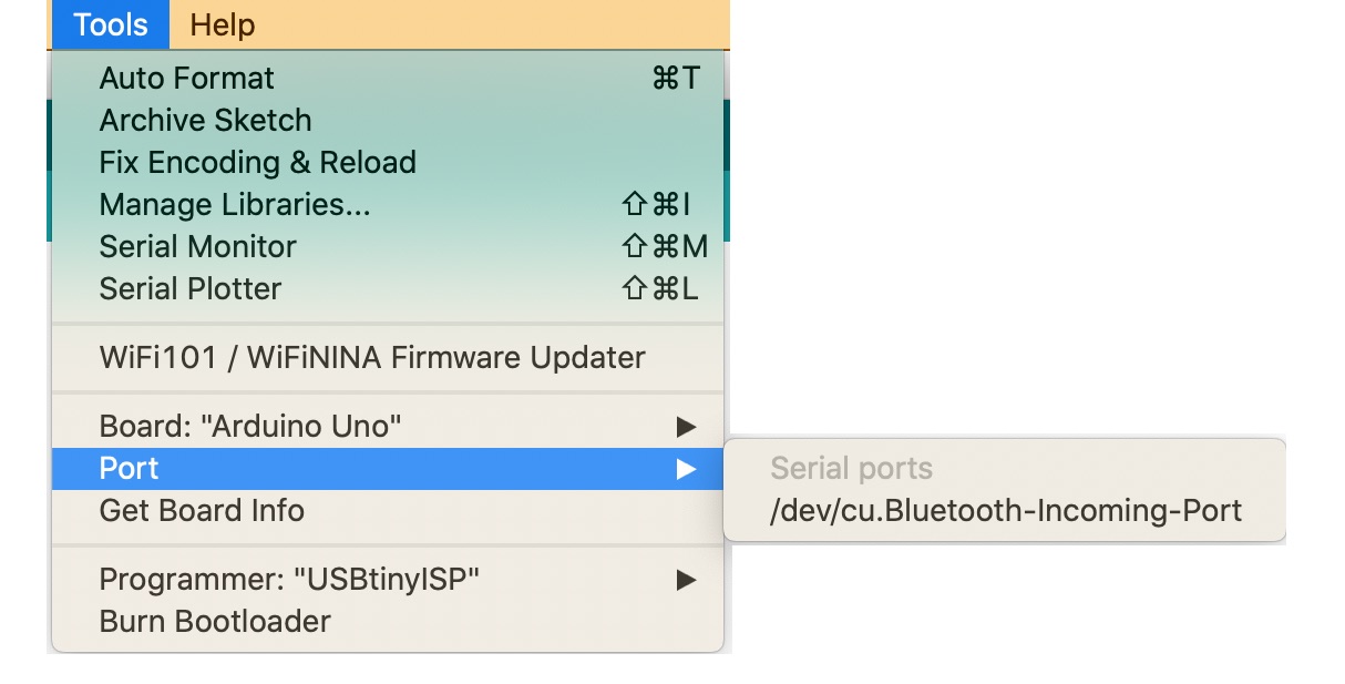
I tried it again and just saw that the port isn't coming up and just won't work. Jonny then helped me realise I had put the wire in wrong! I really am struggling with this and all I have done today I made it sense me but nothing else!
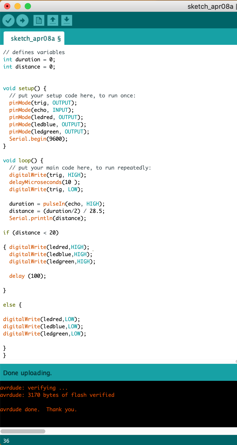
I followed this tutorial which thankfully worked for me. I was really struggling which this as a project and trying to get it to work was making me very annoyed as I am still slightly confused at what I am doing as arduino is quite confusing when learning so much as once.
Hysterisis - when the voltage is jumpy lines
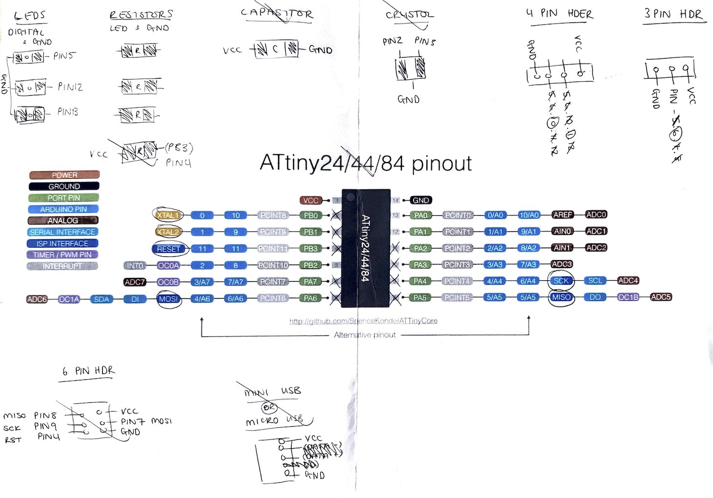
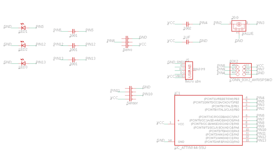
I started by printing off the the pinout for my chip I was going to use which was the ATtiny44. This really helped me to understand what I had after looking at the pinouts from Niels board that I followed in week 6. This showed me what to use and how to get them to all come together which really really helped me to get the correct pinouts for my components.
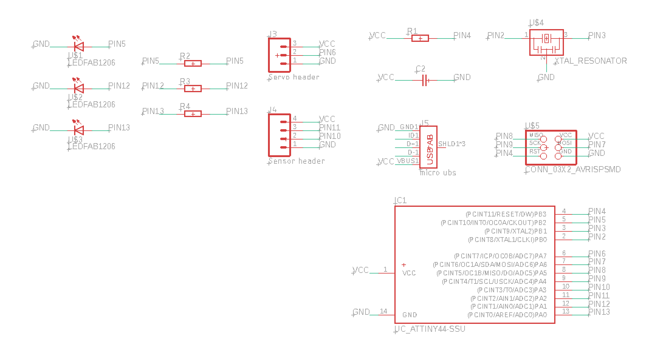
I then when into eagle and getting the schematic to come together by following what I had written on the paper when above. This I found very very useful and think will be my new technique for the future when designing my boards so that I know I have all the components and everything matches up.
I then pressed the 'board' button for it to be produced into the correct format in eagle for me to add the traces and getting the pads correct for the components I was going to be using.
I found it easier to follow Neils board as linked here above so that I could get the first few components in place before I started adding my own. I did this during week 6 so I knew what I needed which was very handy.
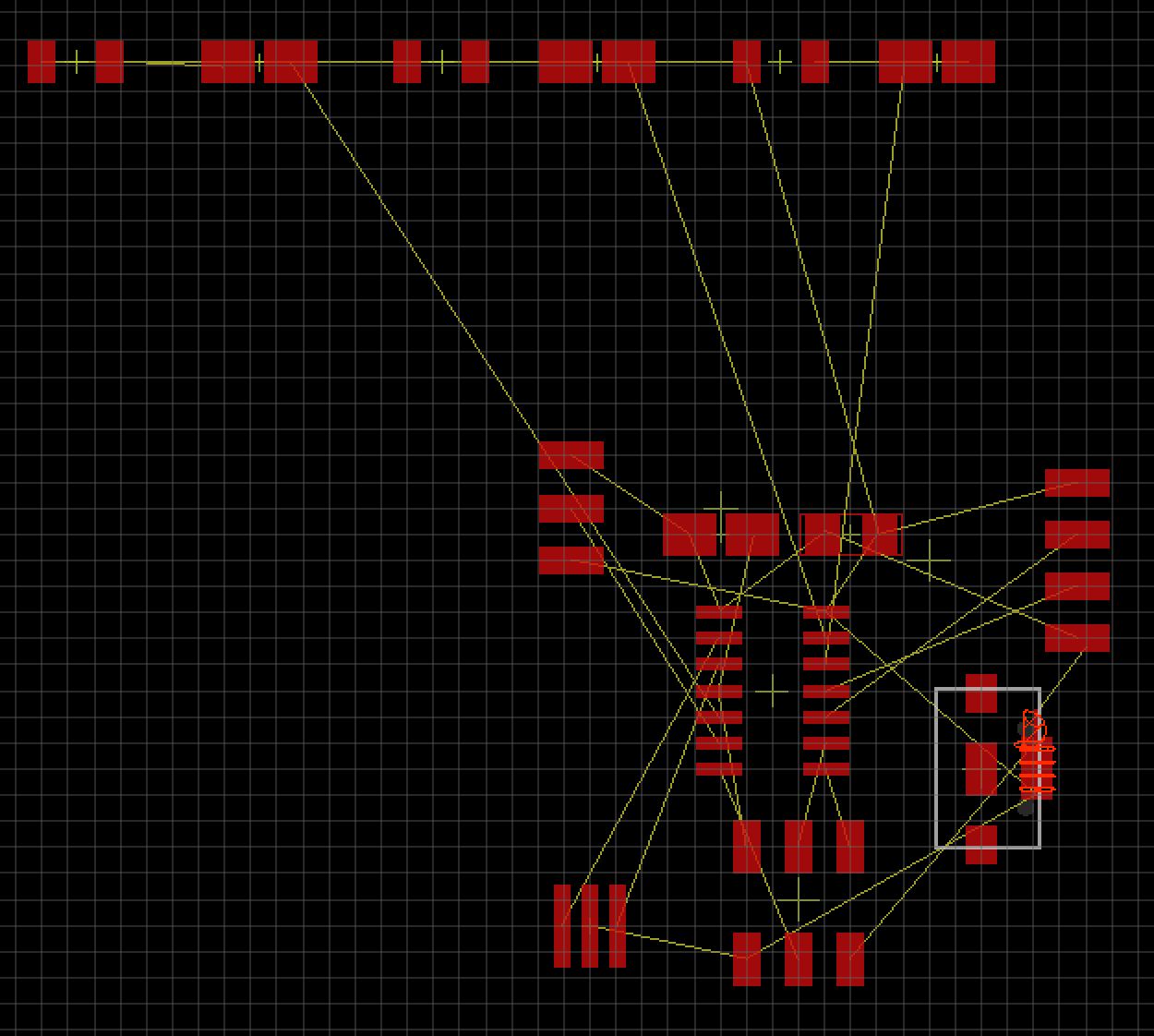
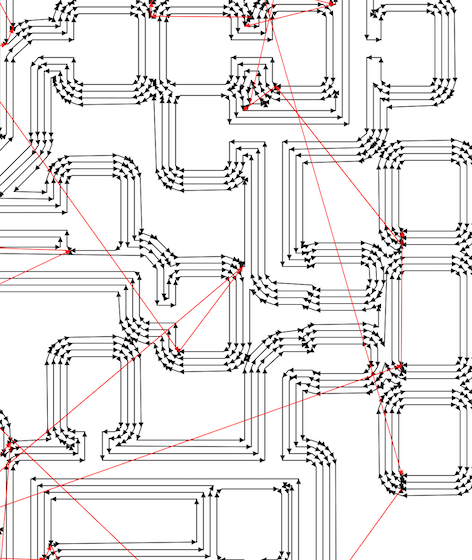
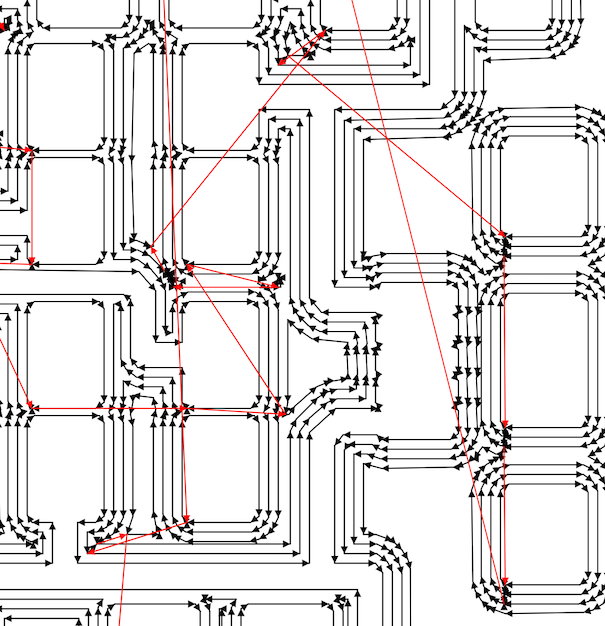
I then realised it was easier to have all the foot prints separated so that you can see each part and the yellow lines which shows you where they need to connect to. Adding all the traces so that they don't overlap I the wrong places was very hard and getting this to work was going to be a struggle I could realise that now.
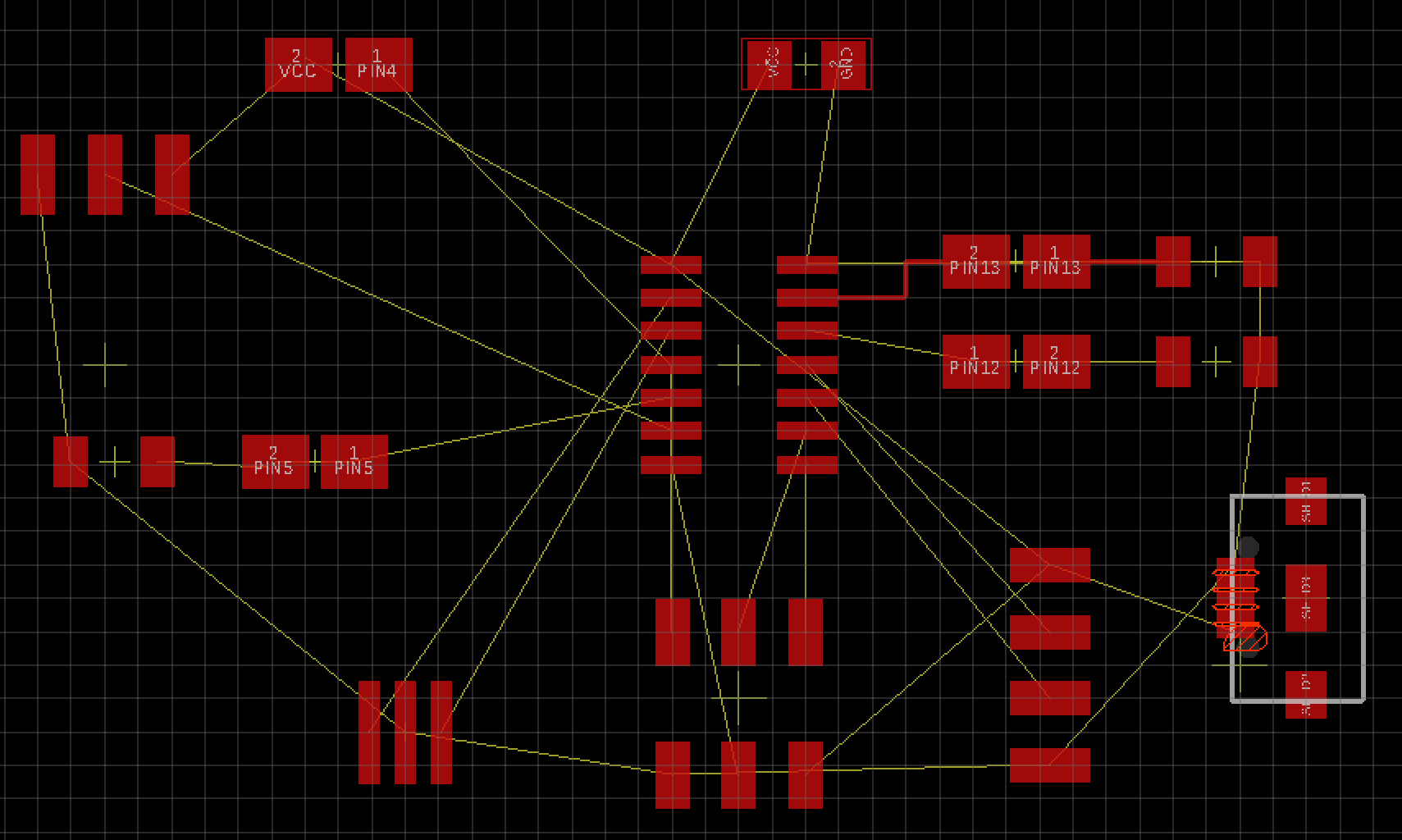
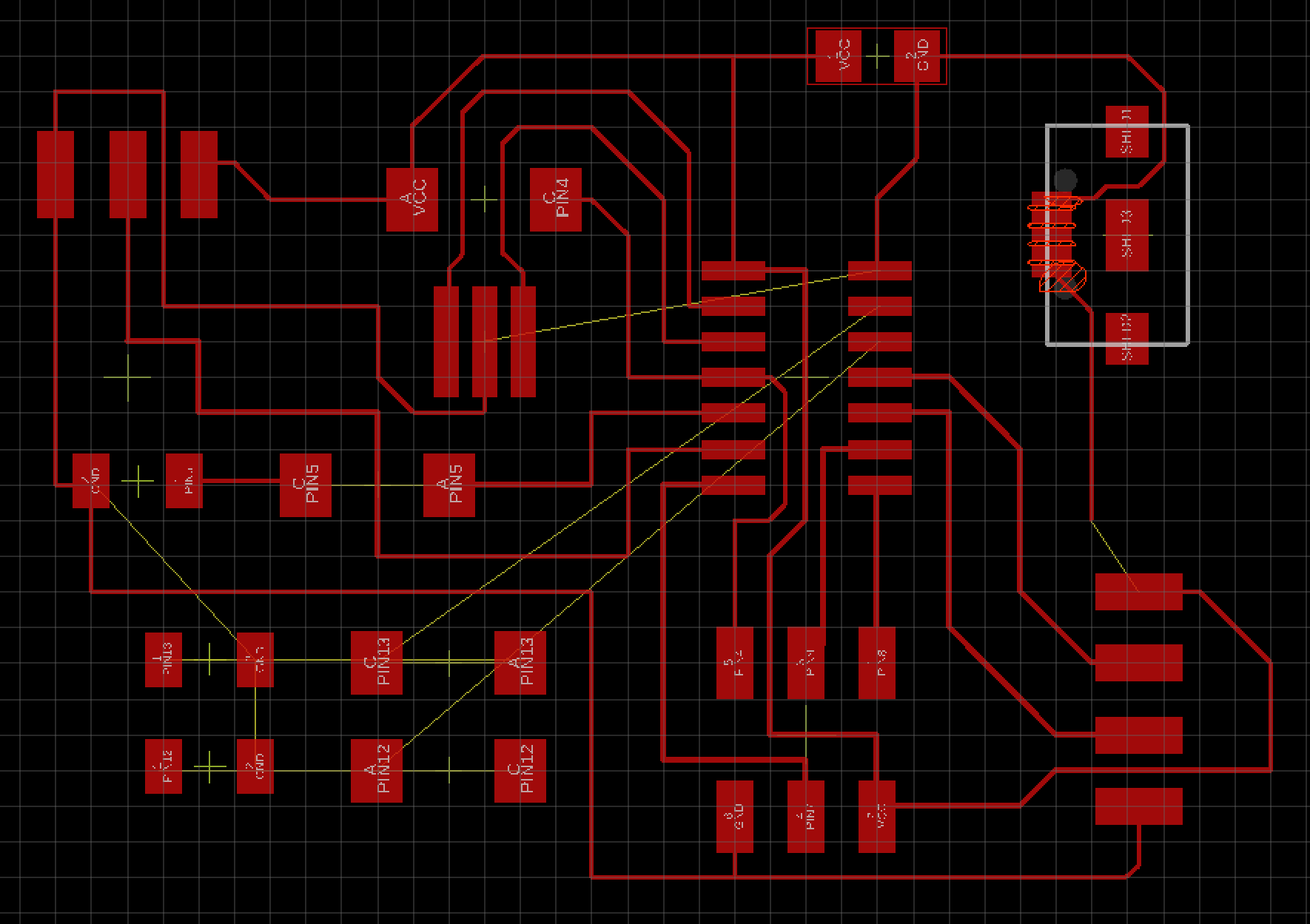
I kept trying to get them all to connect and with also making sure the traces aren't too thin as this makes it harder to use and solder later on.
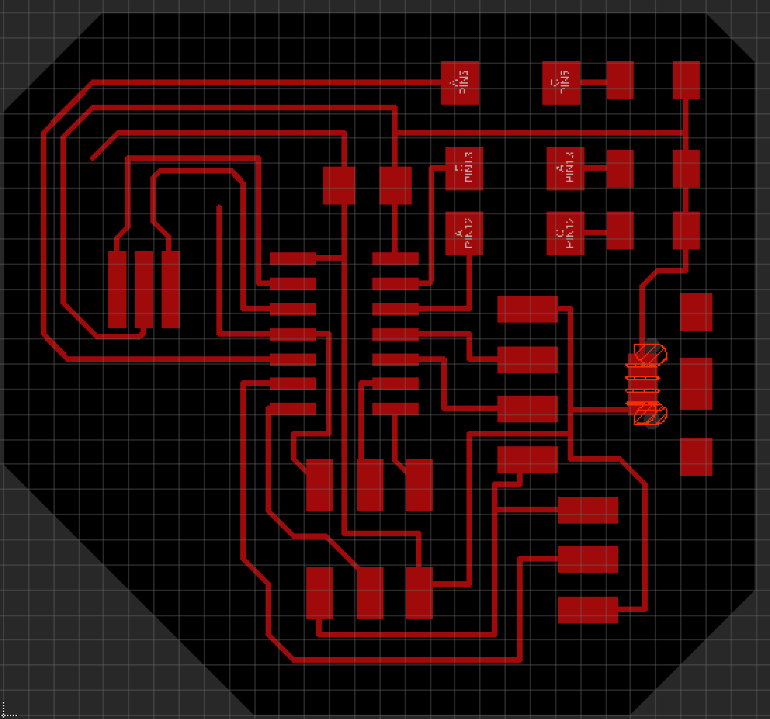
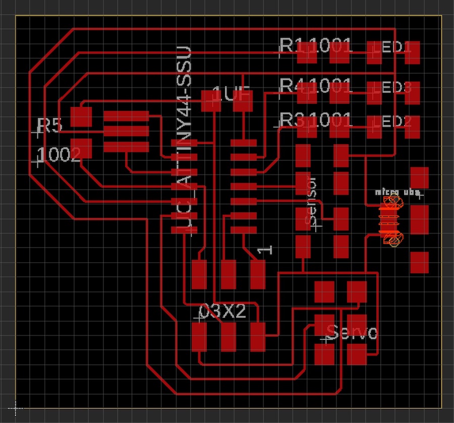
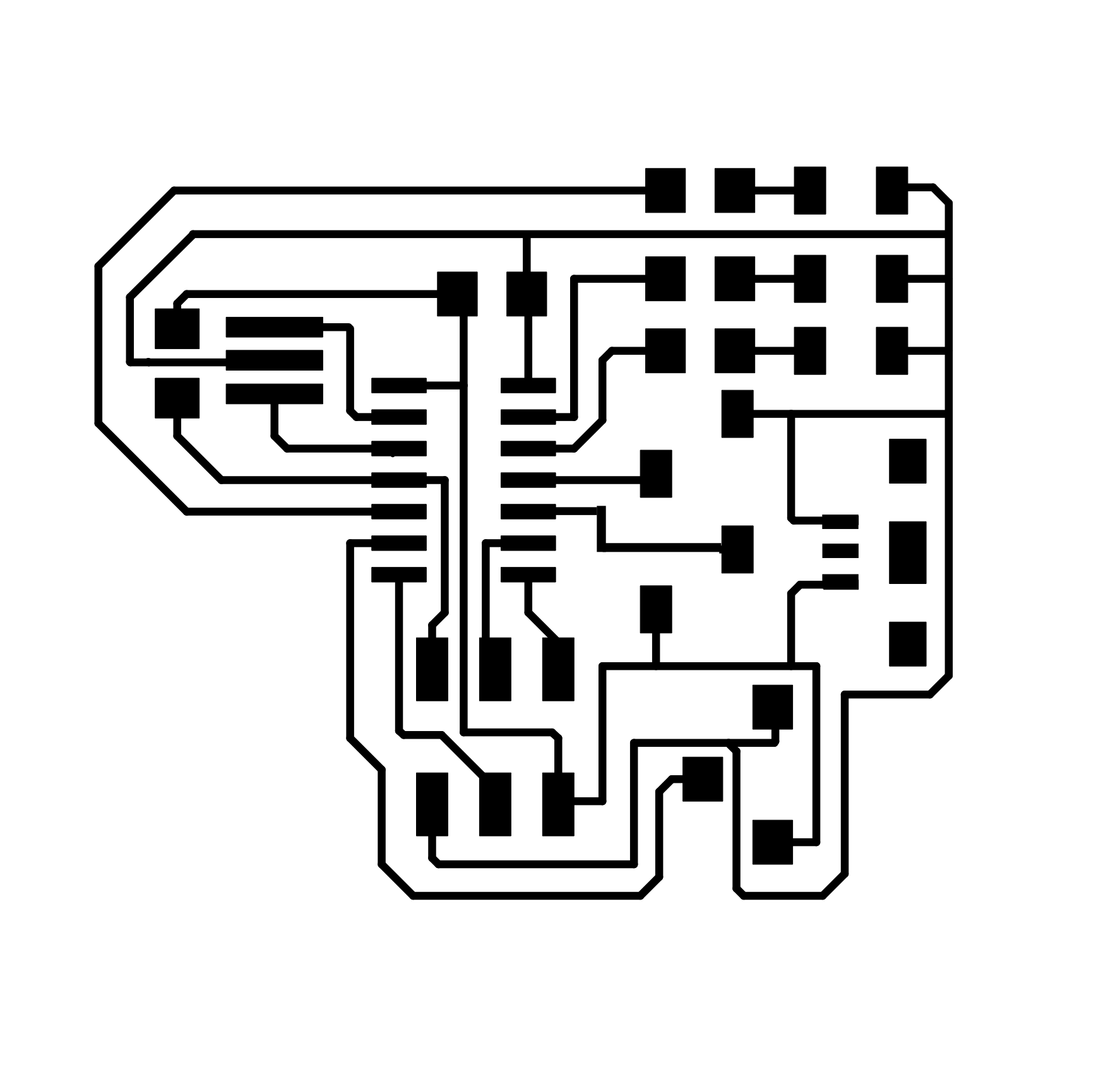
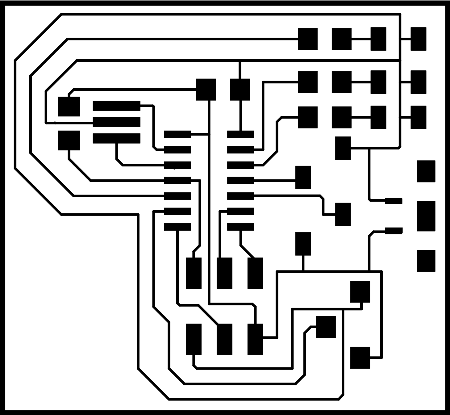
I final got a final outcome for my board which I then printed and added the components to see if I had them correct for the foot prints I had chosen.
Sadly the three and four pin header wouldn't fit on the ones I had chosen as the ones I had are opposite sides that are pinouts so I needed to find one that would be the correct footprint for that.
It was very difficult to get this correct so what I ended up doing was getting a 3x2 pin header and just getting rid of the pads that weren't needed during my check in the preview on my Mac.
I also noticed that whatever I did that in mods it wouldn't let the pads on the micro USB separate, luckily I would not be using these pads as I won't need the two outside ones the VCC and GND.
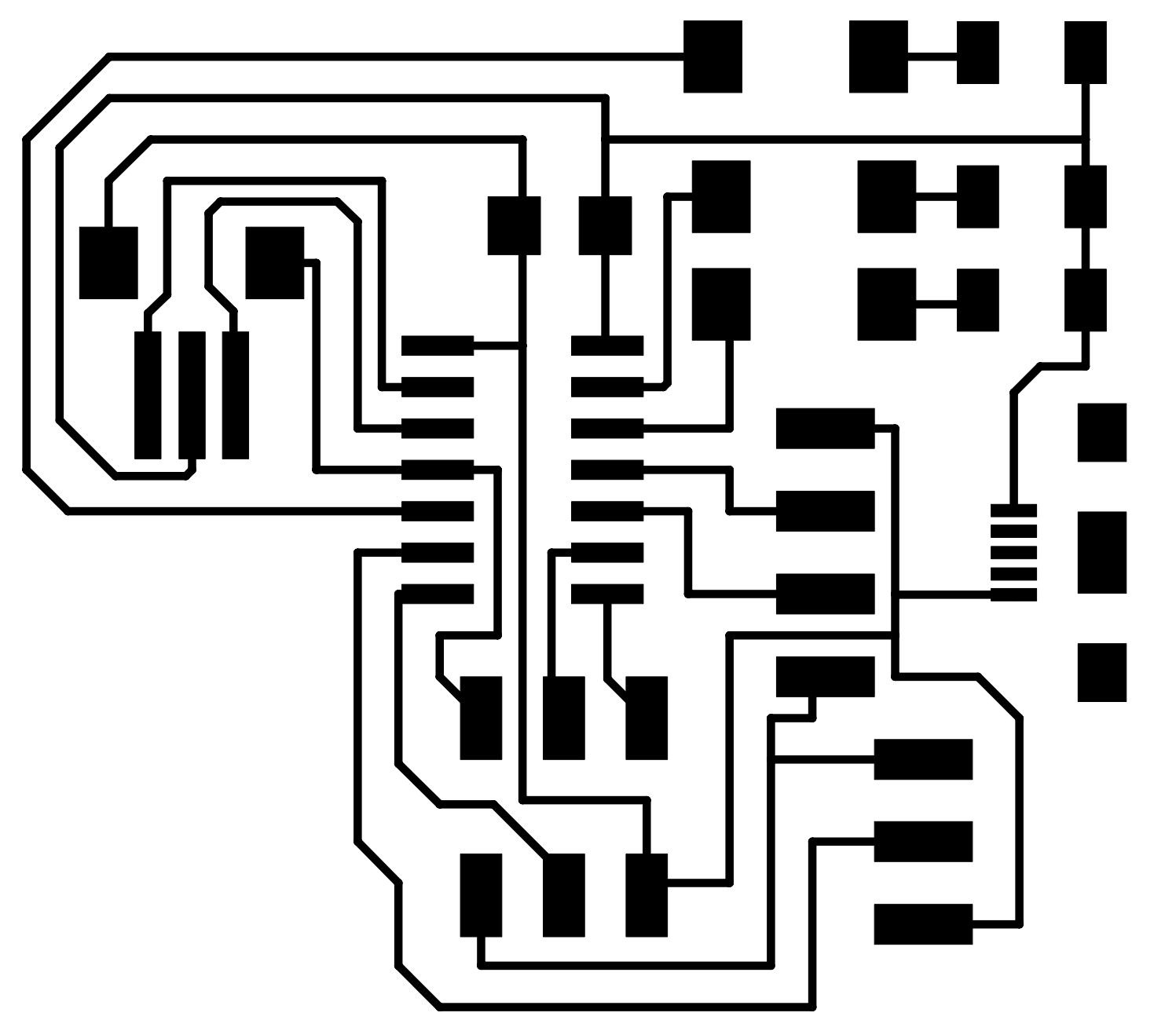
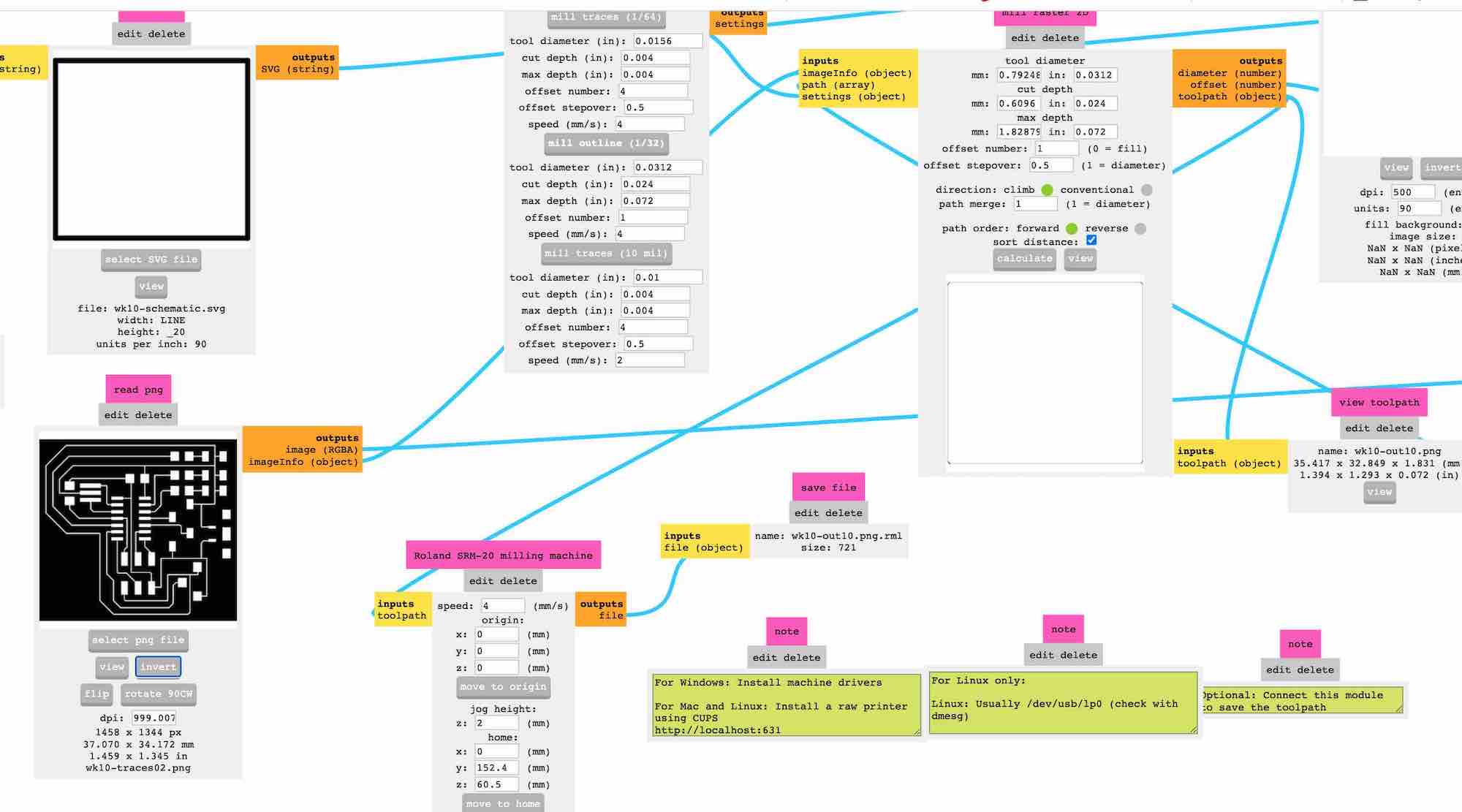
Traces are slightly wider = 16 so I changes them to 8 as it didn't look like it was cutting it perfect when calculated in mods
First board cut out traces and outline. As you can see on the right side and the bottom of this photos the traces very nearly got taken away when I cut the outline. This is something I have really struggled with when using mods and the SRM-20.
Me stuffing my board and then realising that the micro USB was not lined up to the edge so therefor I have to cut the edge off as this was the only thing I could think of otherwise I would have to make a whole new board... turns out I should have just done that.
As I was cutting it sadly I went too hard and the corner of the board got snapped off.
I then decide to try and solder this back together but this took about 40 minutes and it just didn't work! I burnt out an LED which was a pain and I ended up just starting again as you can see.
As I started using the machine for some reason It started doing this very odd thing...
Every time I have set the origin I have done everything correctly but the machine does a tip on the material and then it jumps up to 60.50 for the Z axis. I am going top check eagle toes what the origins are for in there as the SRM-20 panel is coming up as 0 for each origin as I set it.
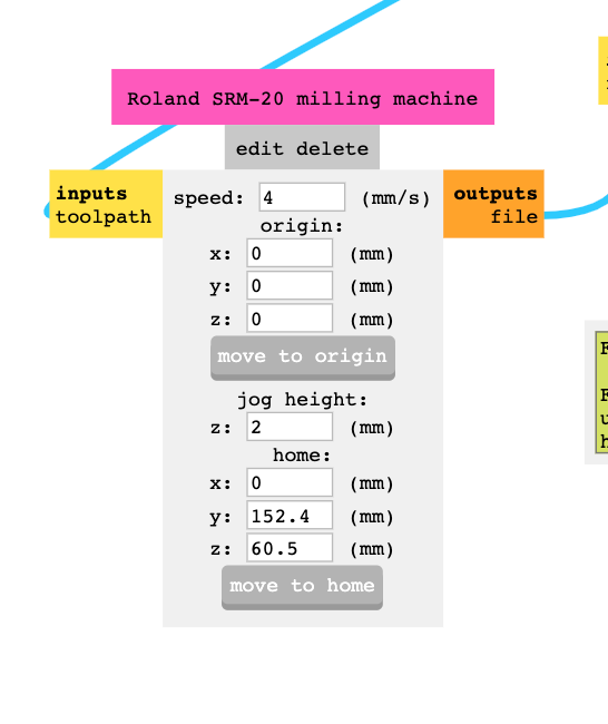
I think this is the issue! This needs to be here as this gets the job to home but for some reason it is stopping the machine from cutting correctly and I am not sure why.
I went back to week 4 to see if this is if this was set in the same time as that? I was the exact same numbers, so I have no idea why it is cutting in thin air!
I have turned the machine off and going to see if this helps whilst keeping those numbers in the home in mods.
This worked! - technology ey?
I then started to check the outlines of my boards so that the micro USB would be on the edge of my board. This was a very long and painful experience as I just kept just looking at the machine and doing air cuts to see what would be the best outline. I thought I would see where the machines cuts, and what I found out is that it cuts on the inside of this black box I had made.


As you can see I tried many different ideas and I realised I hadn't just made a box around my board and then copy that and make it my outline. This worked very well which I was pleased about as I wouldn't have known what else to do.
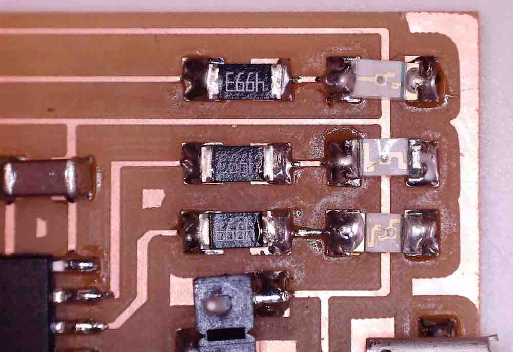
I also decided to make a close up of the LEDs we have so that I could know what was on my board but also so I knew what different they would need to go on my board. You can also use a multi meter if you are not sure what direction they are meant to be facing.
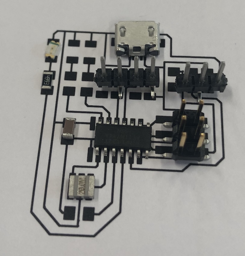
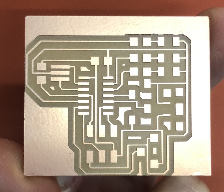
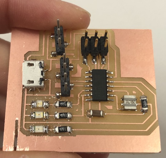
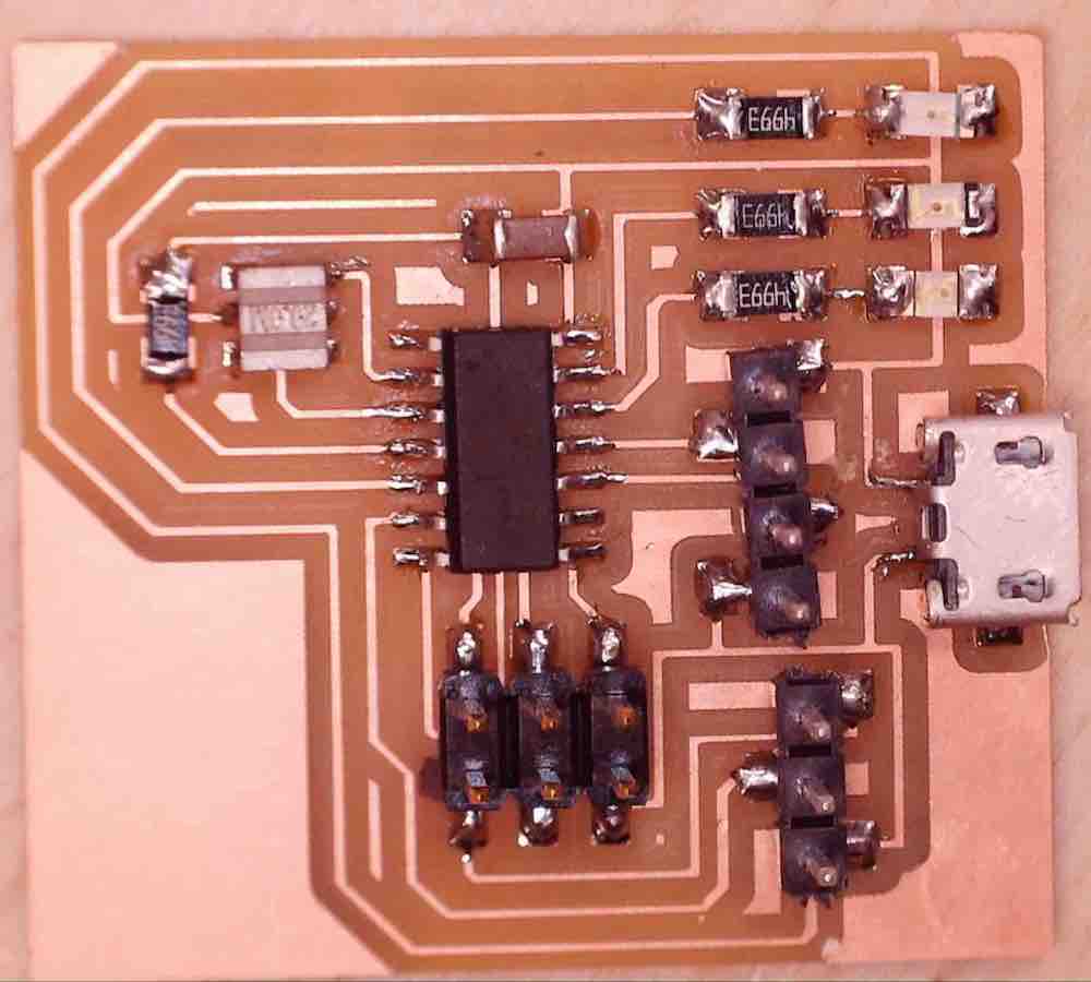
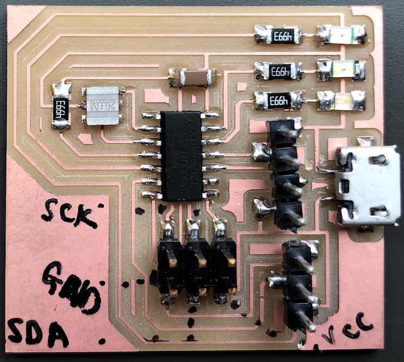
This is my finished board ones it was soldered and stuffed!
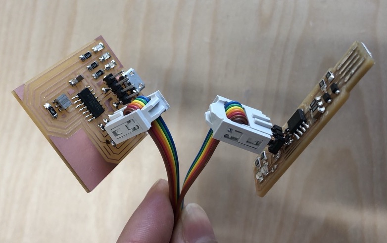
I plugged in my programmer from week 4 which I had made and it worked so thought I had some hopes for getting this board to work with the programmer.
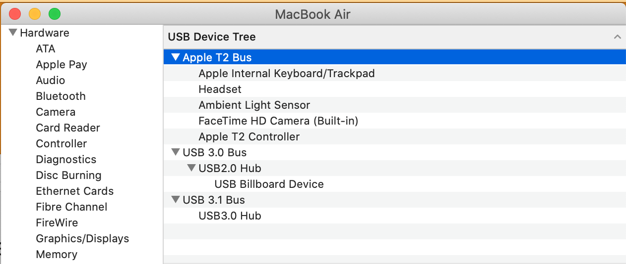
I was having issues which my board coming up in the USB area of my Mac to show that it is being recognised in the ports. Sometimes it would come up and other times it just wouldn't register it was coming up at all. I ended up it many times in each port using different USB dongles and this ended p being very confusing and had no idea what Iw as doing was helping.
I was also noticing that it just wasn't coming up on the arduino port either, I contacted Andrew to see if this was something to do with my programming board which he said the ti could be many things. I thought it could be my board but he didn't think it would be the board as there are many other variants right now that are against me.
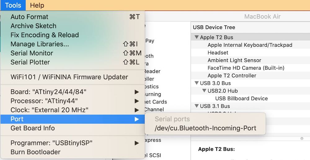
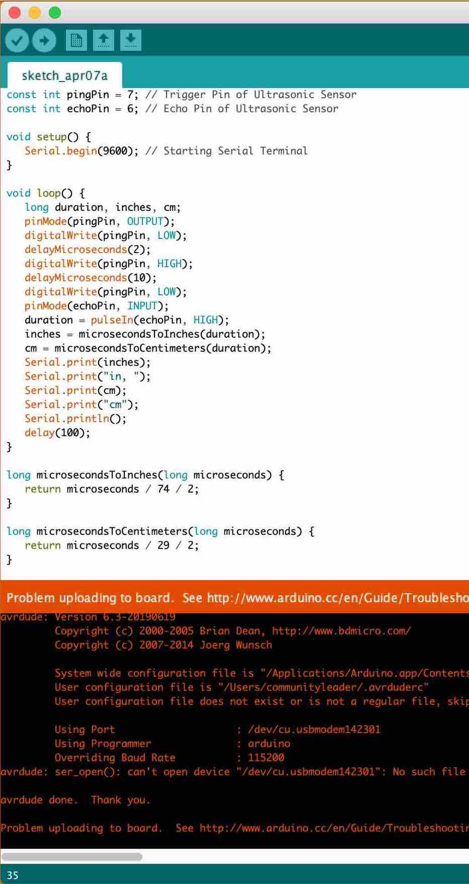
Every time I kept trying to complete and upload the sketch I would keep getting an error with what ever I did, restarting arduino, choosing a new sketch, making the port, the bus converter and everything else!! I was about to give up when...
Andrew suggested to restart my computer and then try it and see if the port is really that necessary as he thought that maybe because of both my boards they don't come up.
If I'm being honest I wasn't that pleased with this outcome, I think A) it has been a very long day for me so I was tired and ready to give up and B) because I had lit an LED so many times I was just done with this specific part. I have made designed and stuffed this board and now I was just using it to light an LED.
  int led = 2;           // the PWM pin the LED is attached to
  int brightness = 0;    // how bright the LED is
  int fadeAmount = 5;    // how many points to fade the LED by

      // the setup routine runs once when you press reset:
  void setup() {
      // declare pin 9 to be an output:
      pinMode(led, OUTPUT);
    }

      // the loop routine runs over and over again forever:
  void loop() {
      // set the brightness of pin 9:
      analogWrite(led, brightness);

      // change the brightness for next time through the loop:
      brightness = brightness + fadeAmount;

      // reverse the direction of the fading at the ends of the fade:
      if (brightness <= 0 || brightness >= 255) {
      fadeAmount = -fadeAmount;
    }
      // wait for 30 milliseconds to see the dimming effect
      delay(30);
    }
The next day I took a step back and actually what I have achieved is AMAZING!
I have successfully made a program that can program other board I have design, cut and stuffed to light up an LED... I have NEVER done anything like this before and think a pat on the back was well deserved.
Well done Katie!! Keep going we believe in you... now try out the board as it mean to be used!
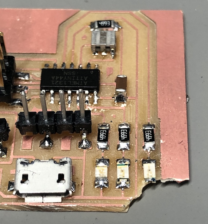
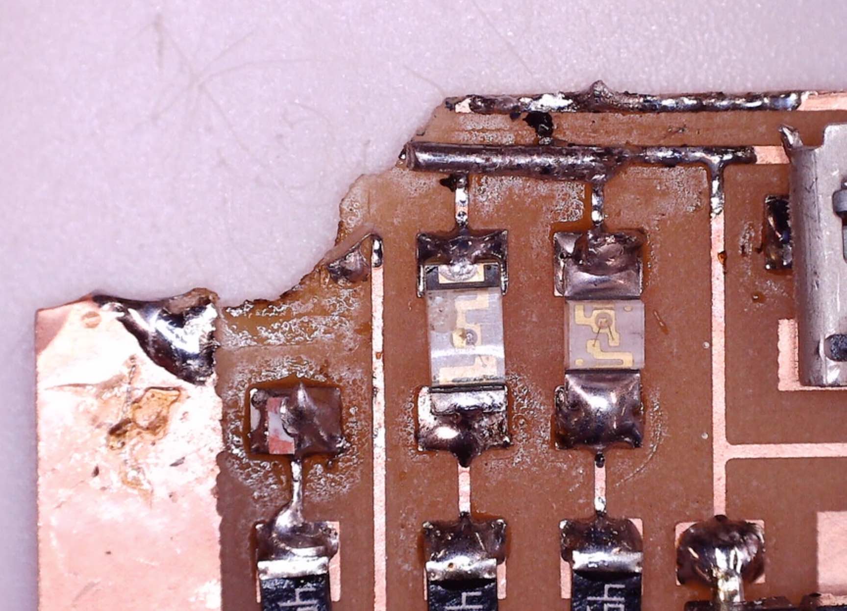
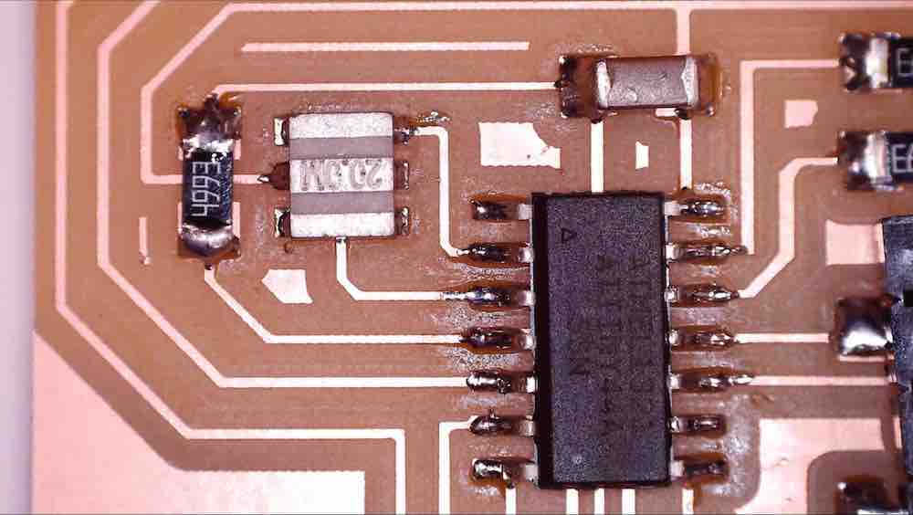
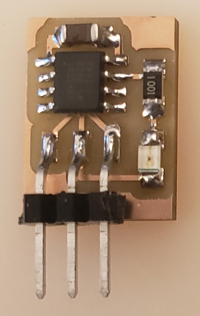
As you can see I struggled to get my leds to light up on my board but did get it to work when I used an external led, this was because I used the correct resisitor. As pointed out in global evaluation and you can see on the board I have used a '4993' resisitor on each of the leds, this is therefore too large for the leds to get them to light up. The resistor '4993' is 499k where as Neil's board used a '1001' which is equal to 1k so you can see it is 500 times too large and that is why my leds are not lighting up.
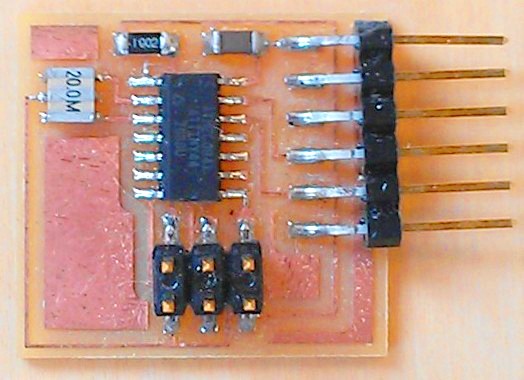
I also made the mistake and placed a '4993' resistor instead of a '1002' by the crystal and therefore this is 50 times too big compared to Niels board which as said is using a '1002'. I have made this mistake and I am still learning about resistors and which one goes where, I think now by using neo pixels and figuring out the output of a devise this has helped me understand more.
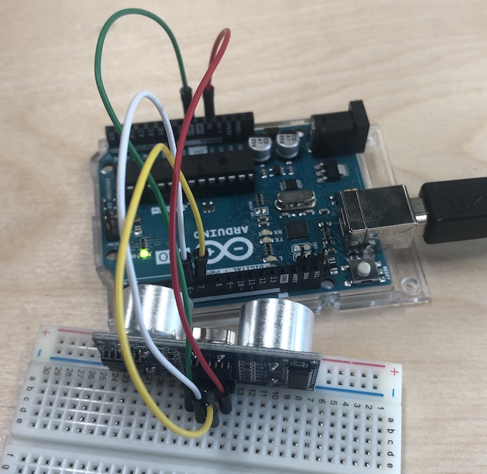
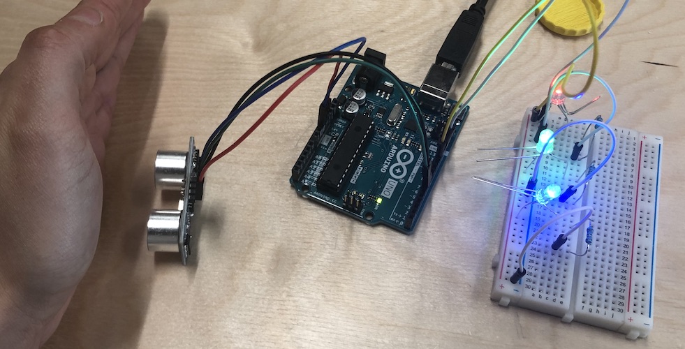
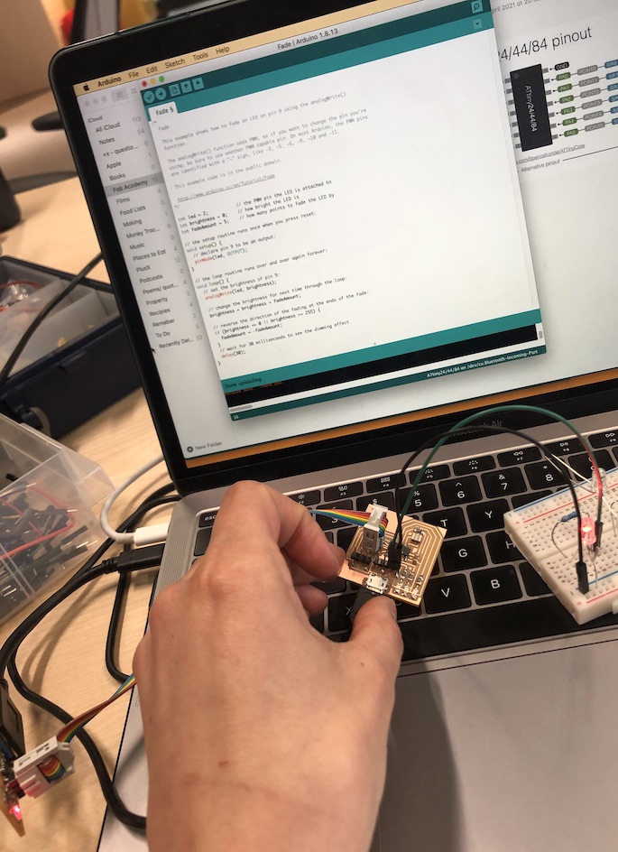
For my final project my aim is to get a line of neopixels to turn on via a sensor that would feel a cap fall past it. Here is a video of this outcome with my own board with a 32U4 chip and the neopixels behind the acrylic and side glow. I used a ultrasonic sensor to sense my hand going over it for now but in the future it will sense a cap falling which is very exciting!