4. Electronics production
Electronics Production week was amazing that I never though I could make a USB by myself. Thanks to the Fablab teachers, I received a wonderful gift for 2021.
PCB fabrication
Printed circuit Board (PCB) Fabrication helps the ideas in your mind to change to the products you made. And simplifying the fabrication process, you can design and create a circuit board with a computer and etching machine.
PCB Development normally has three process, including design, manufacturing and testing. This week we had manufacturing and testing stages and week 6 we will learn how to design a circular board.
PCB manufacturing
1. Preparation for the etching machine.
- Set the parameters for the board by Fab Modules and output the files.
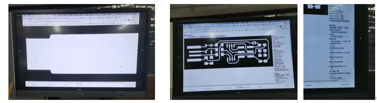
- We chose the FR 1(Copper based on Paper) as the materials for PCB, as the base of FR 1 is paper which is fit for the end mills in our lab.
- Check whether the output files is the same with the origin circuit and whether there are enough room between traces. If you use the end mill of Diameter 0.4 mm, the room should be bigger than 0.4 mm.
2. How to print a accurate and beautiful board ?
- Choose the correct type of end mill, we use Diameter 0.4 mm. The sizes of the top of the end mill normally has 0.4 mm (1/64 in) and 0.8 mm (1/32 in).

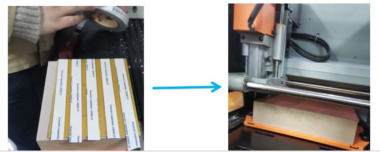
- Make sure your workbench is clean and flat. If not, choosing the surface cutting to planish the plane.
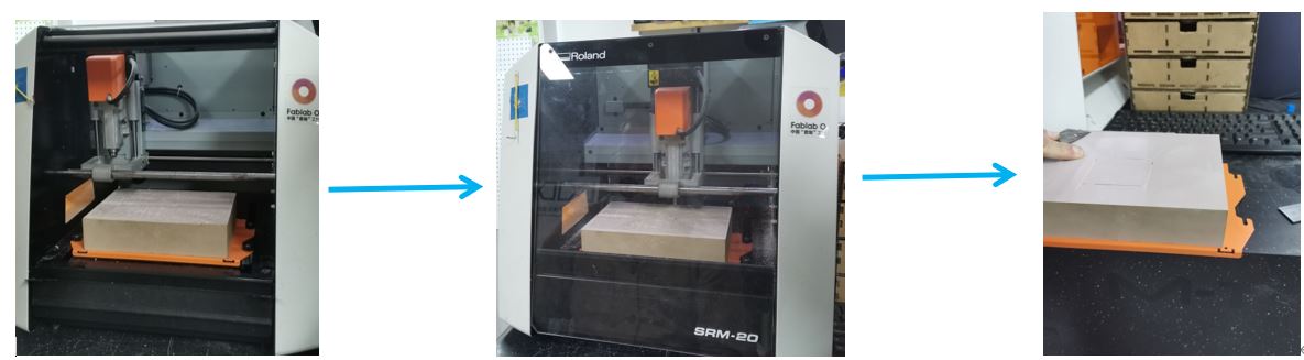
- Paste your materials to the workbench with the double-side tape and keep it very very flat without any bubbles or dust. The time spent on the process is much valuable as you will receive one accurate production. The double-side tape should be easy to take away to make sure the surface of Copper is flat.
- Set the origin for X, Y, Z axis.
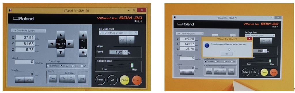
- Import the files and print them.
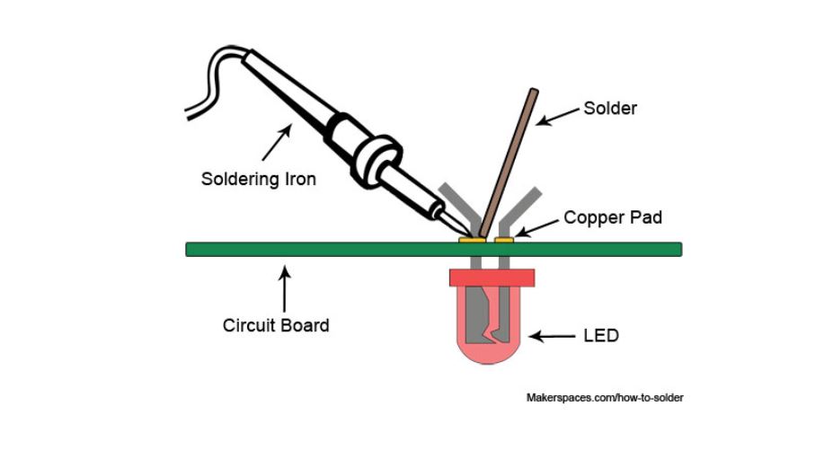
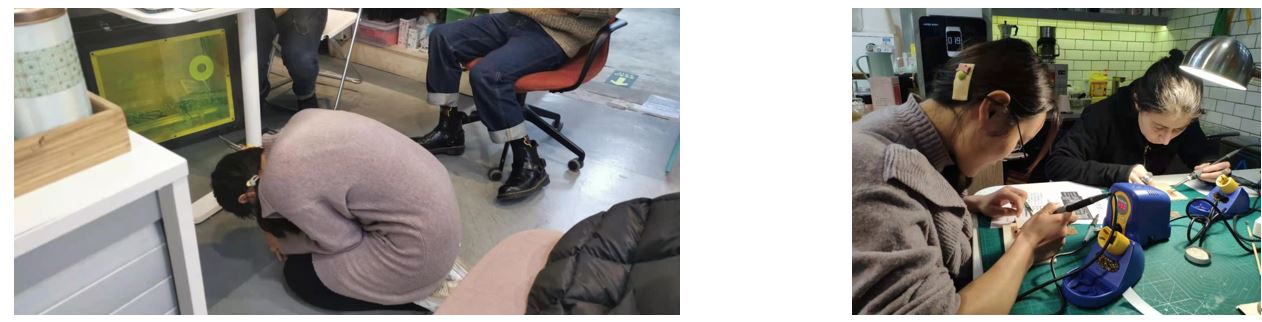
3. Soldering the board
- We first learn how to solder, found the correct components according to the instructions and solder the components to the board. Before soldering, I removed all the copper in the edge of the connecting part of the USB.
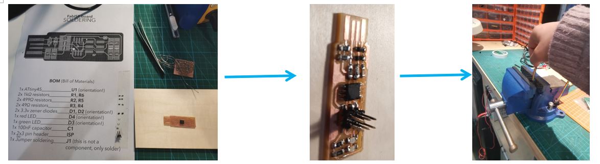
- Soldering steps: firstly, set the temperature at 450 degree. Secondly, touch the board for seconds and heat the board with the soldering iron, allow the solder to touch the board and the soldering Iron for seconds and the solder melts , remove solder and keep the soldering iron heating the board for seconds, then remove the iron and the components and circuit board join together.
- During soldering, several stories happened. First, we misunderstood the value of resistance, treated the 49 K as 49. Second, the circuit board pasted to my coat and I couldn’t find it. It fell down to the floor until my instructor threw my coat. Third, I misunderstood the direction of LED. Fifth, clothe pasted to the tape on the paper and my friend tried her best to seperate them without destorying the paper.
Group Assignment
This week’s group assignment is to run a milling precision test.
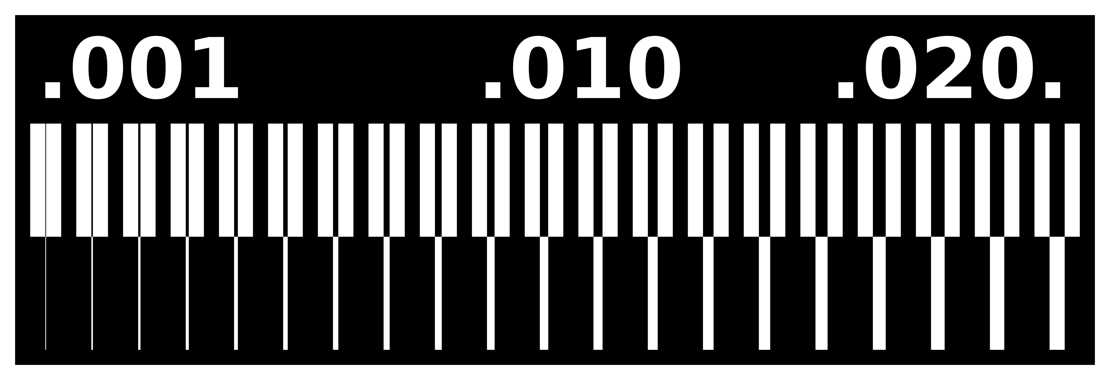
We test the precision of the milling machine by cutting a board shown in the picture above and find the thinner line that it could cut is around 0.001”.
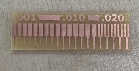
More details please check Chloe’s website.
PCB testing-building the Fab TinyISP
Steps
1. Software Installation
- Install GNU Make, Avrdude and Atmel AVR Toolchain for windows, but AVR doesn’t work for Win 10. So I installed WinAVR 20100110.
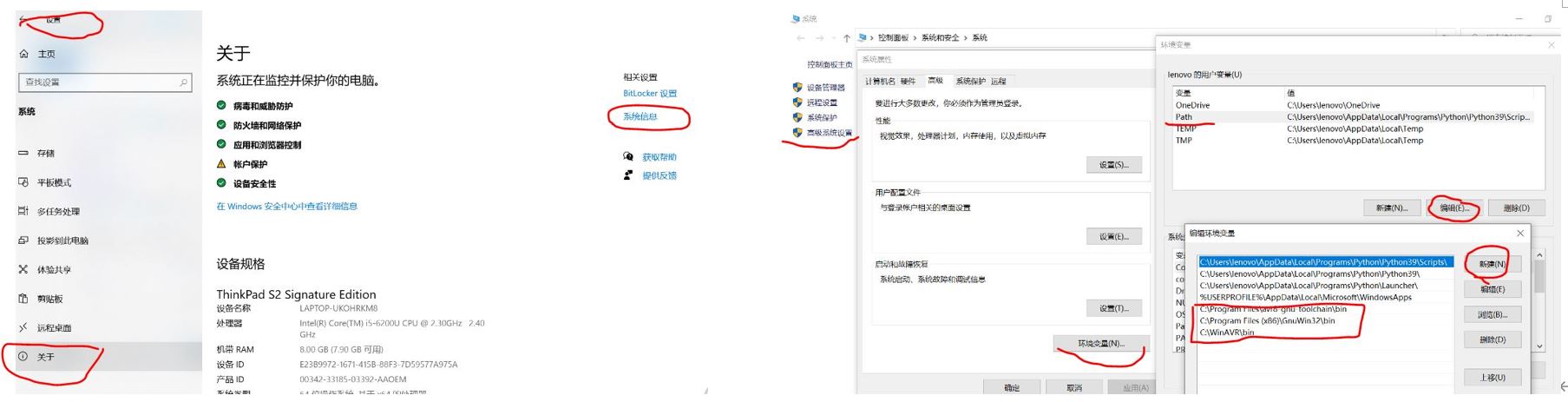
- Update the Path.
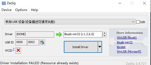
 - Install Drivers for the programmer.
- Sanity Check. Type the commands and press enter seperatly in Git Bash. Re-check the installation or the path of the softwares if you get a ‘’command not found’‘ errror.
make -v for Gun Make 3.81
avr-gcc --version for AVR-GCC
avrdude -c usbtiny -p t45 for Avrdude
2. Get and build the firmware
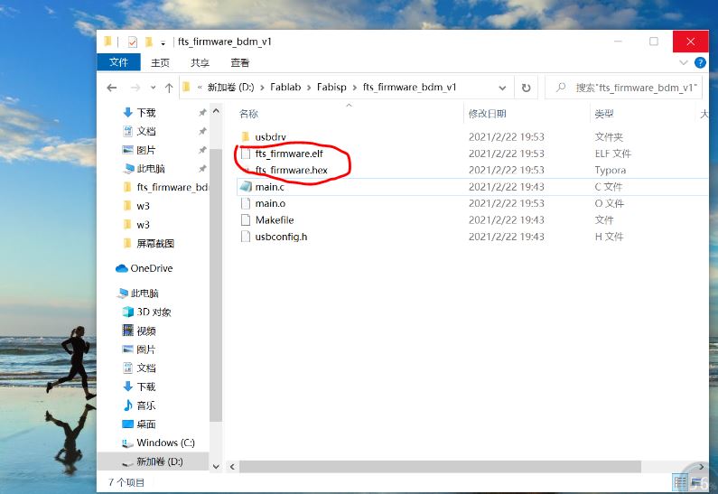
- Get and build the firmware. Download the firmware source code and extract the zip file. Open the Git Bash and
cdinto the source code director. Runmakeand two new files will be produced.
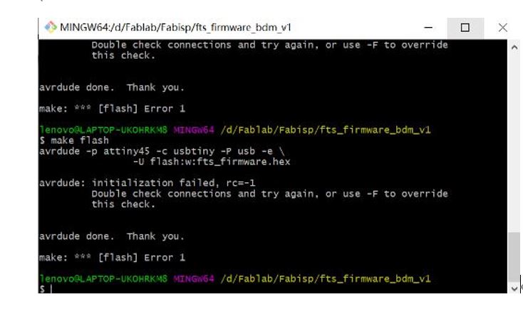
3. Program the ATtiny45
- Run
make flash

Problems & Errors
- Installing
I used to install softwares in the disk D:, and I did this but the softwares didn’t work as the Git Bash couldn’t find them. So I installed again and put them in the disk C:/programe Files.
-
I use Windows 10, it can install the AVRdude but the Git Bash couldn’t open the AVRdude. Luckily, We found the answer from Meha-hashmi. Following the Meha-hashmi’s steps, installed the old version WinAVR 20100110 and replace several files with them of Version 6.3.2016.
-
The circuit board didn’t work when I test it the first time. I melted and soldering it again and it stilled doesn’t work. I’ll keep debugging it in the next weeks.
Update
Considering there maybe something wrong with my soldering skills or the components I used, I decide to cut and solder the second FabISP. However, the new FabISP still doesn’t work, I will continue working on it.
- Use the multimeter to test whether the pins are connected or not. The result is that all the components works well.
- Test the second FabISP with different computers, different lines and different FabISP to connect with. It doesn’t work. So it’s the problem of the board, not outside factors.
- Clean the board with alcohol by the toothbrush, use the multimeter to check the connection several times by different people. We couldn’t find the problem.
- We decide to give the FabISP several days to rest and hope it will works.
- Later my instructor buy one small machine to check the function of microcontroller. And we find the microcontroller ATtiny 45 I use is broken. So I start to use ATtiny 412 in the electric boards and ATtiny 412 works very well.