3. Computer controlled cutting
This week I learned the different cutting methods and started to use the laser cutting, worked on the cutting project idea.
Group Assignment
How to design a vertor model for laser cutting
- The designing softwares I used are Adobe IIustrator, Fusion, Inkscape.
- The laser cuts materials by burning materials, it will burn around 0.04mm~2mm per time. The vector design should consider the loss, especially when you design the joint part. If you want a 5 mm 4 mm square, the draw may be 4.8 mm 3.8 mm.
- There are three kinds of laser cutting, including totally cutting, half cutting ( only line shapes), surface cutting. Normally you can choose one color for one kind of cutting. I chose black color for the graphic, surface cutting firstly, half cutting secondly, finally totally cutting.
- The same elements of the vector model should be convienent to edit together, as you will test one part of the model several times until you get the right one.
How to use a laser cutting machine
- Our fablab use carbon dioxide as the laser resource, the gase volume should be checked firstly. With the gase volume reducing, the power of laser also changing. We should attempt and find the approprate setting each time.
- Secondly, open the machines and focus, send the file to the machine and press the start. Before cutting, the lens should be check and clean by alcohol.
- PPI: 500 for paper, PPI : 1000 for wood & plastic.
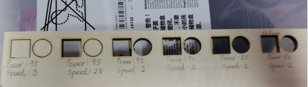
- The power for cutting the 3 mm wood is 85%, the best speed is 2.
- The color of draft should be RGB, the stroke line alway be 0.05mm.
- For surface cutting, DPI is 300, Speed is 60.
- Option: choosing the placement.
A parametric press-fit construction kit
Usefull Link

2 D models design idea
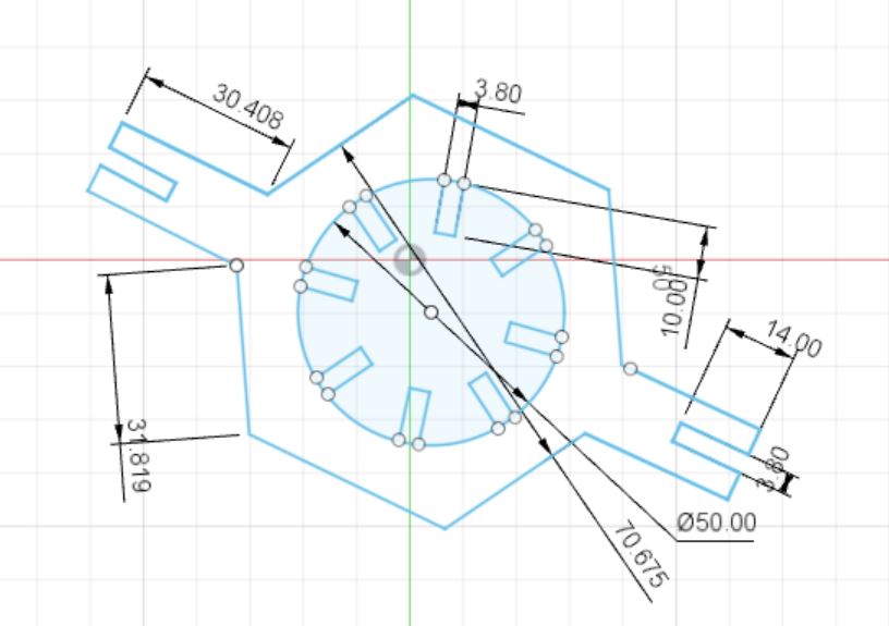
Lantern Festival is coming, I wanted to DIY a lantern. And I was inspired by the information above. And I designed the models by Fusion and saved the sketch as the .dxf. I was trying to modified by Inkscape but it didn’t work for the AI on the computer linked to the laser cutting machine. So I simplified the models and use the cardboard with 3mm thickness.
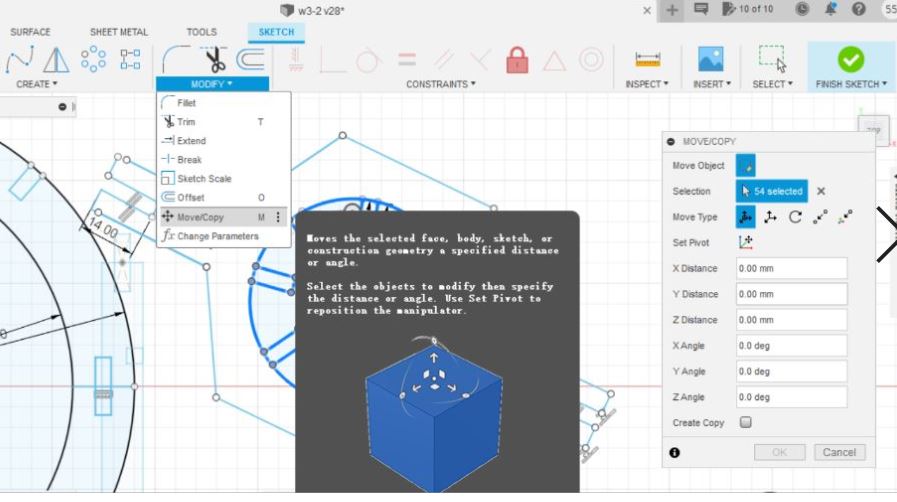
After the first cutting, I found the two models could be merge, I combine the two models together by clicking the Sketch-Modify-Move/Copy, which allow to cut more pieces with limited cardboards.
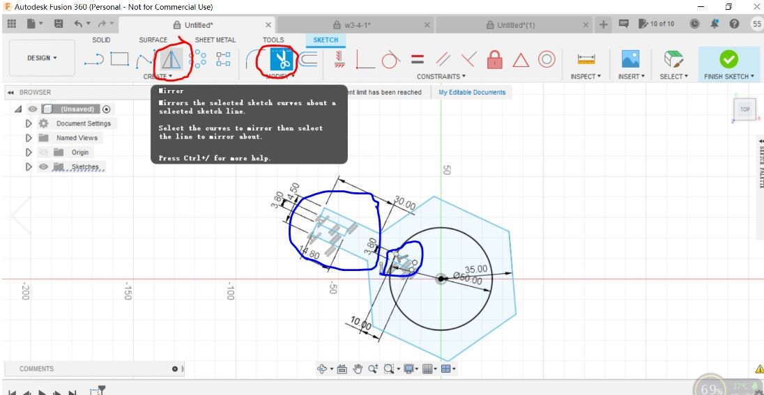
The designning steps - Create a sketch, build the plane and draw the basic shaps.

- Cut the overlap lines by ‘Trim’ function, sysmetricly replicate by ‘Mirror’ function.
Laser Cutting
I spent several hours to use the laser cutter although I have learnt how to use it.
Problems and Errors
- The first problems that I met is that the illusion files couldn’t be printed. I though there was something wrong with the connections between the computer and machine. In fact, it caused by the files itself. If the .dxf documents that saved by the Fusion, it will work for the cutter. But if I use other software edited it and it won’t work.
- The second problem that I met is that the parameter didn’t work which I set in the ‘print-performance’, if there is something wrong with the shapes in the graphics.
- The third problem was that the size of the shapes changed in the computer linked to the machine. And I didn’t know how to change the size exactly, so I attempt several times by zooming in or out until it’s the right size.
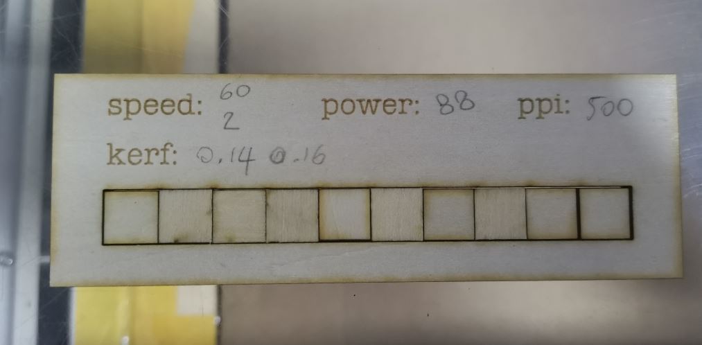
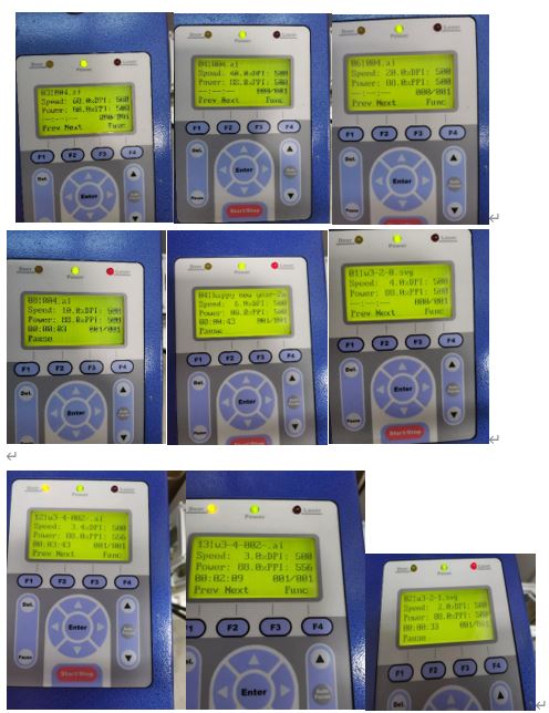
Seeking the appropriate parameter - The power is 88% based on the group assignment. - The appropraite speed is 3 for 4 mm cardboard and 4 for 2 mm cardboard. - PPI: 500 for paper, PPI : 1000 for wood & plastic. - The kerf is for 3 mm cardboard. The 3 mm cardboard couldn’t be cut or damadged until the speed is from 60 reduced to 10.
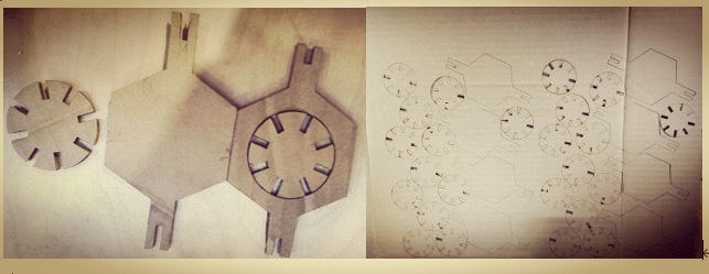
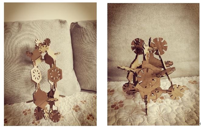
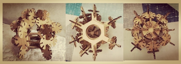
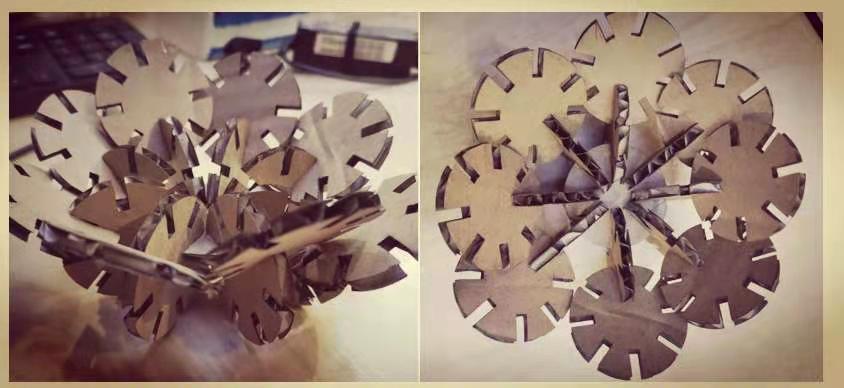
The kit I attempted to make a lantern and a ball with limited pieces. Can you find the lantern from the pictures following?
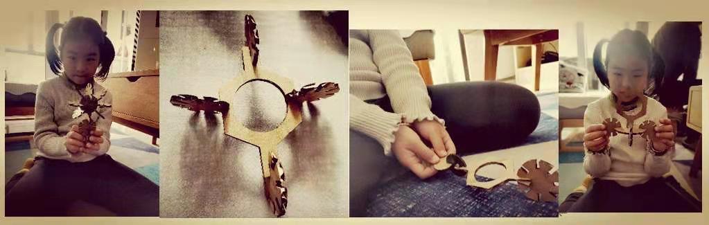
I got an angel to help me to use the 3 D models. The sweet girl was interested in the cardboards and tried her best to create some toys with them.
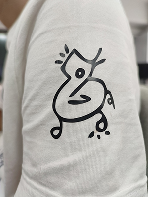
Vinyl Cutting
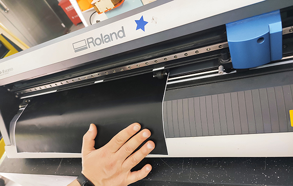
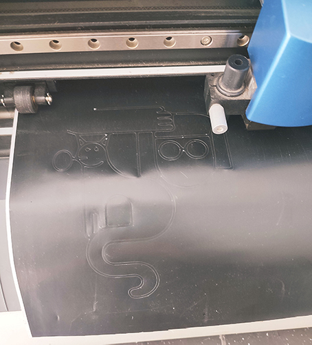
I am interested in the vinyl cutting machine as its operation is super simple and can cut varies funny stickers. The machine we use is Roland GX-24, Serial No. is FBV2743, Input is 24 V & 2.8 A. And we use Cut Studio software to import the files that I want to cut. You can design the shape in software. Or you can draw a simple shapes on paper with Mark pen, take a photo of it, open with AI, save as . eps file in Illusion 3 version(Cut Studio in our computer can only open this type file in Illusion 3 version). I am interested in the second way, take a photo of the draft and open with Illusion. Use Object ---Image Trace---Make and Expandto change the raster picture to vector, Select---Same---Fill Color to make sure all the paths is black, Object---Path---Simplify to reduce the path points and get a better shape.

How to operate the machine?
- Fix the paper roll and put the paper horizontally.
- Use the arrow buttons to change the location of needle . Set the X,Y zero by putting the end mill? in the left-down corner of the paper.
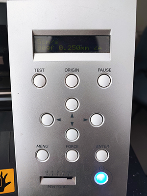
-
Run a test and check whether everything is going well. If force is not OK, you can change the pen force slightly to make sure there has enough force to cut the shapes without breaking the paper totally.
-
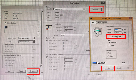
Import “the file and set the parameters by click
Cut--- Change---Properties--Get from Machine---OK, drag the pattern in the right location and cut it.
- Cut off the sticker by moving the needle from left to right and cutting one horizontal line.
- Positive sticker can directly use, while negative sticker need to paste it with tape. Make sure the tape has less glue that the sticker can easily get off the tape when you take the tape off from something that you paste to.