5. Electronics production
This week I worked on FabMdules, the Roland milling machine and with soldering in order to produce my first programmer PCB.
Characterize
The machine I used was the Roland Modela MDX-40A. It is a very powerful and precise machine, as well as fairly straight forward to use. This is most likely my favourite machine in the lab. It is my belief that this machine is actually out of production at the moment as Roland as progresed to newer and update models, this machine informations can be found here.
CAD to CAM
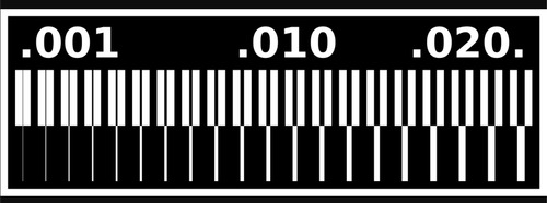
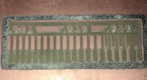
The first step was to download and inspect the .png files that rapresented our distance and trace test tool.

The second step was uploading the trace file to FabModules.
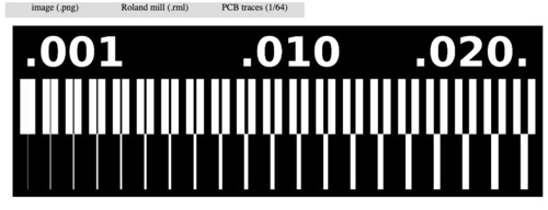
Selected options:
- input: image
-
output: Roland cnc format
-
process: pcb trace (1\64 inch)
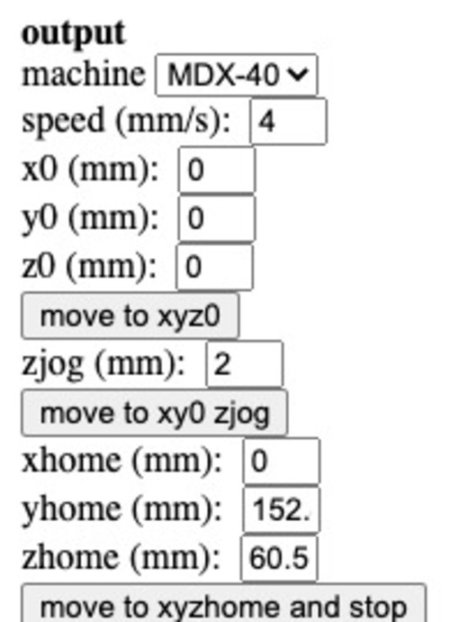
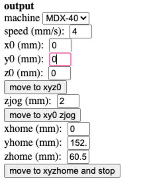
Selected:
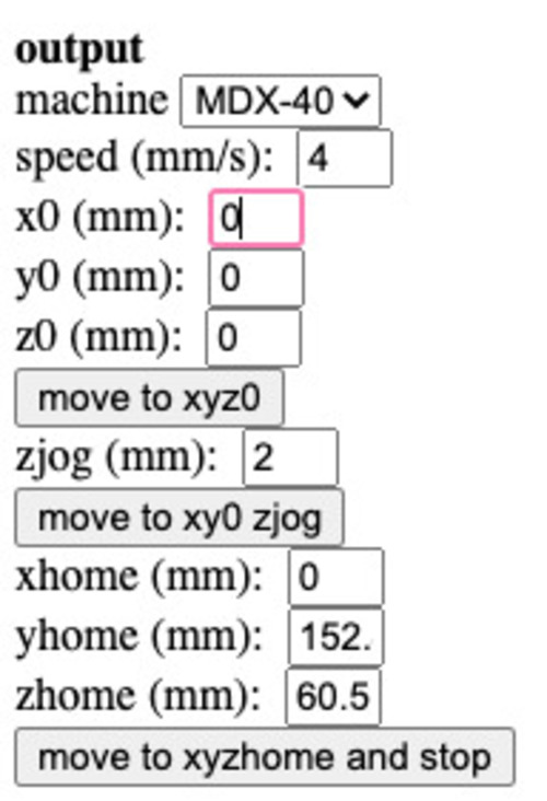
- machine: MDX-40
-
offset from origin: 0 on all axis
-
speed was not varied
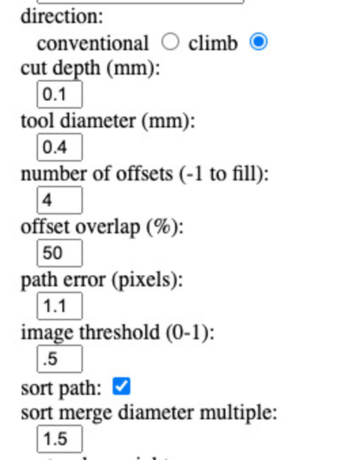
Selected:
-
tool: 0.4mm mill end
-
cut depth: 0.1mm
-
offset: 4 with 50% overlap
Trace result calculated.
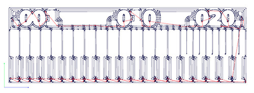
The third step was preparing the outline CAM file.
- input: image
-
output: Roland cnc format
-
process: pcb outline (1\32 inch)
- machine: MDX-40
-
offset from origin: 0 on all axis
-
speed was not varied
- tool: 0.79mm mill end
-
cut depth: 0.6mm
-
offset: 1
Outline result calculated.
Tools
These are the mill ends I used.
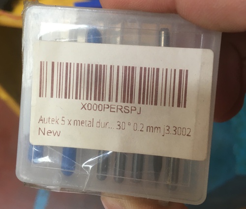
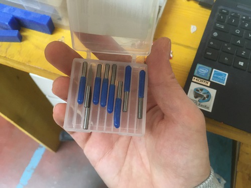
0.2mm 30° V-bits, these were used for the traces in all my tests and final pcb.
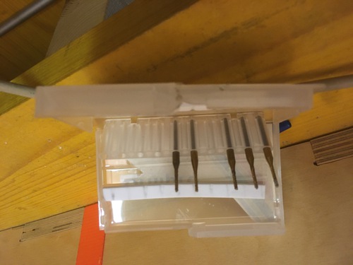
0.79mm flat bit, I used these for cutting the outlines.
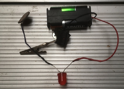
This is the Z axis probe we use at Opendot to determine the point of contact in between the copper layer and the drill bit:
the pinch is attached to the bit, while the base sensor is pressed against the copper layer, when the circuit is closed, a LED light would turn on. This was massively helpful to precisely set the Z axis, and to quicken the tool change process.
Preparing the machine and the material
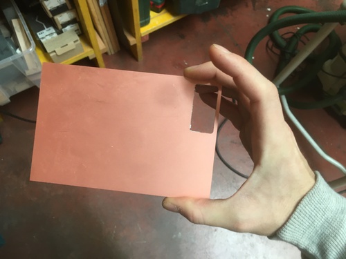
I chose a nice and clean FR1 copper laminated phenolic paper. I did some extra cleaning with white spirit.
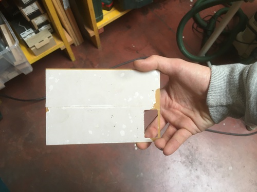
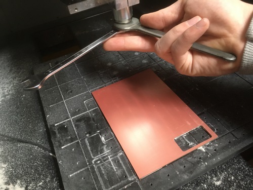
Applied a layer of double sided tape in order to fix the material to the sacrificial layer. I make sure no scraps or dust would be on this layer and that no air bubble would be left under the sticker to ensure the material laid as flat as possible.
Drill bit installed appling limited torque to the set-screw. I still found out this don’t have to be too soft as the drill bit might move and slide due to friction with the material and vibration.
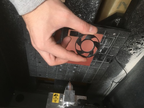
Installed 3d printed fan, to remove dust while the machine is milling in order to maximise precision.
Determine XYZ axis
As I understood that the V-bit trace would be massively impacted by the precision of the Z axis zeroing I exmperimented with minimal increase\decrease in Z axis height, this would impact in the depth of cut and therefore on it’s width, resulting is differences in precision.
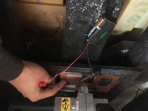
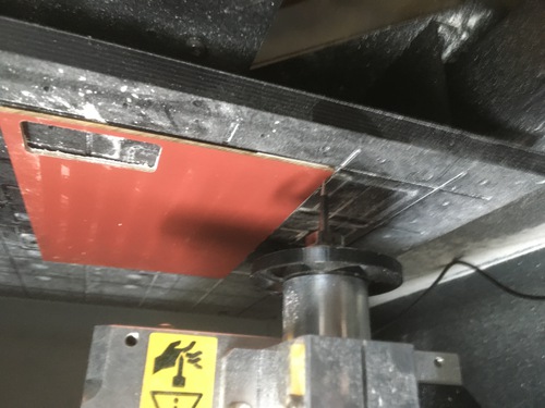
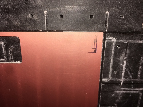
The probe before the bit touched the copper.
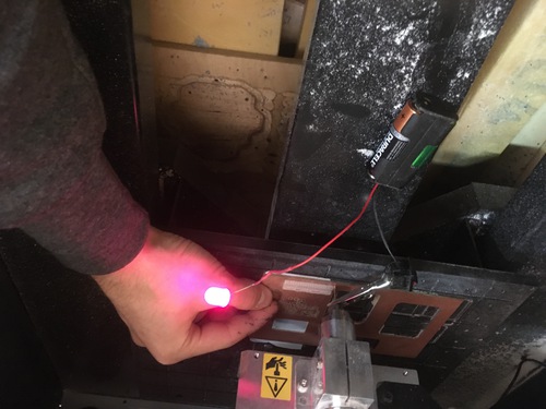
The probe after the bit touched the copper.
Once I obtained contact by moving the Z axis by 10 steps, I moved back by 1 step until the bit was barely touching.
From there I moved down again by small increments, in order to be able to track the depth of my cuts and assess changes and issues.
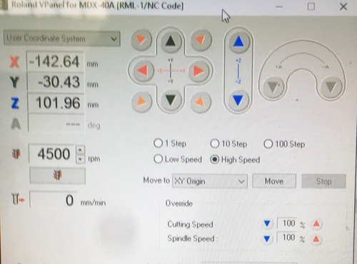
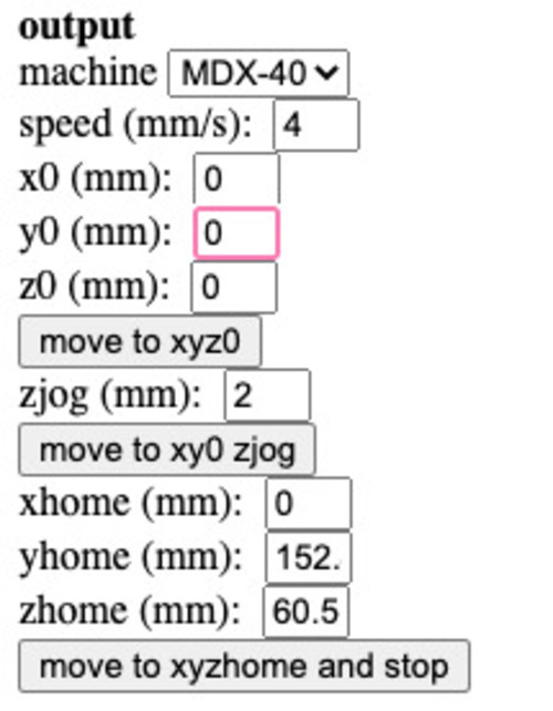
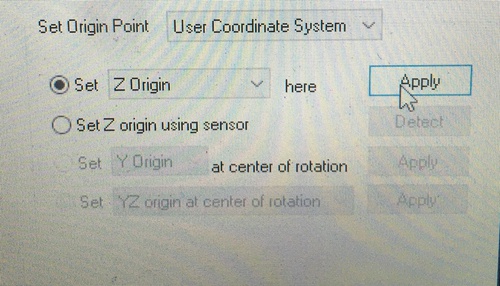
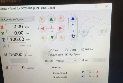
The machine is moved to the preferred XY origin location.
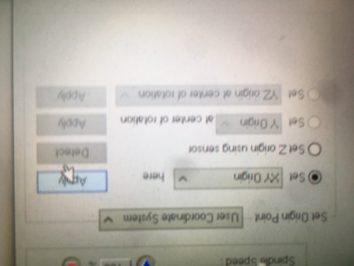
XY origin applied.
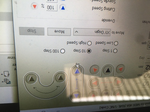
Once the machine is in location I moved it to the centre of the shape I was going to mill in order to determine the Z axis in a avarage spot in order to reduce incongruity in the trace.
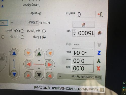
In order to determine the “first light” (contact) of the probe I first moved in 10 steps increment, and then a more precise 1 step increment.
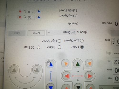
Once I was happy with my Z zeroing I applied additional depth in 1 steps increments and then applied the Z origin that was found.
OG test
The first ever test I did actually happened before I got more rigorous in the Z axis zeroing process. Because I stopped at the 10steps increment in movement there was one less degree in order of manignitude in the precision to determine the Z axis.
This test was not tracked as the following ones and was mainly done to understand the workflow from the calculation of the CAM file, to the machine software setup to the machine hardware preparation.
Before cleaning.
After cleaning.
This bad test actually gave me a good insight. The copper traces edges were flared ad the bit was wider on the top of the trace then at the bottom of the cut surface. This caused the edges to flare, which showed me the importance of zeroing this axis precisely.
Additional tests
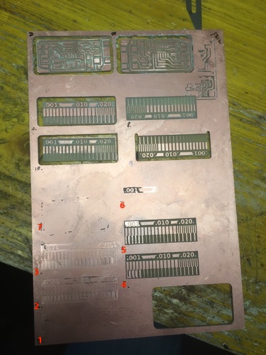
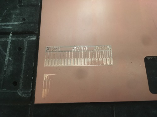
I did 11 tests on the distance\trace tool. Only two of them were actually cut. I did this in order to first find a good position for the Z axis mantaining the original “first light” (contact) setting found with the probe before moving on to changing the end bit. This was done to keep track of the steps increments in depth starting from a common basis.
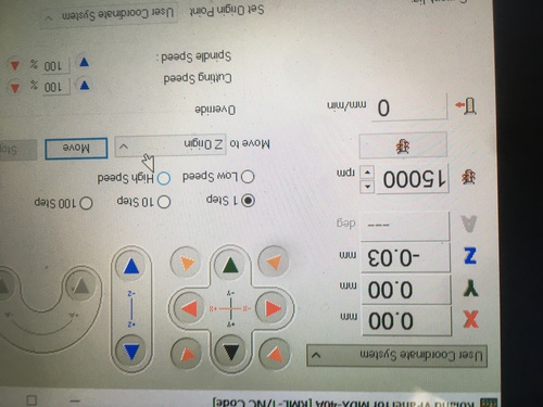
Test 1
Speed was set at 15k rpm. Z axis was lowered by 0.02mm from the first light on the probe.
The drill bit did not managed to trace. The Z axis was clearly too high.
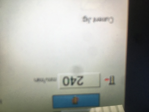
I noticed that the cut speed was fluctuating (from a maximum of 240 to a minimum of 140). This in conjunction with the fact that the trace went into a gradient to the point of disappearance suggested me that the material was probably either warped or too flat. I could have also indicated that I didn’t close the set screws enough.
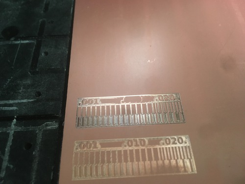
Test 2
I tightened slighly my set screws and lowered my Z axis by 0.04 (total from first light: -0.06).
The result was still presenting a gradient and the mill didn’t make it to the phenolic paper, effectevely managing to solely engrave the copper layer.
There was still a similar speed fluctuation in cut speed to Test 1.
This test meant that my Z axis was stil too high and that the material was probably warped or unflat.
I was quite pleasant to feel the trace with the tip of my finger.
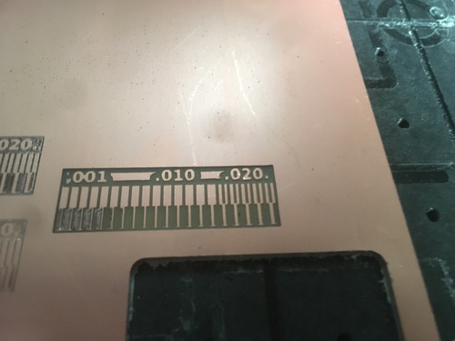
Test 3
Lowered the Z axis by 0.03 (total from first light: -0.09).
This test actually presented a larger area of gradient, but in a different part of the object than Test 2, suggesting to trust my guts that the material wasn’t laid flat enough.
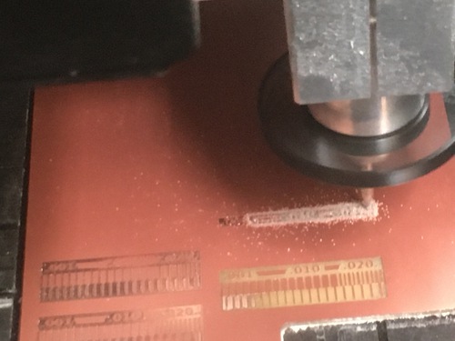
Test 4
Lowered the Z axis by 0.02 (total from first light: -0.11).
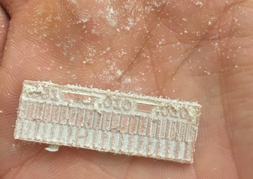
This time the cut speed presented fluctuations more often, suggesting additional friction.
This added friction was confirmed by the first appearance of white dust, showing that the drill bit had finally reached the phenolic paper.
This time the shape had been placed closer to the centre of the material, since the results were better than the first 3 tests, this suggested me that if was probably less warped\more flat here than closer to the edge.
The result still presented gradients, the traces were quite precise nonetheless and didn’t show flares on the copper edges.
Test 5
Lowered the Z axis by 0.02 (total from first light: -0.13).
This time dust did not appeared on the first offset. I am now convinced the material is not flat enough.
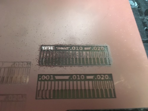
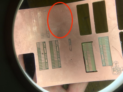
The result presented more gradients in the top area and less in the bottom area as opposed to the previous test. The rest of the traces are now quite precise\neat.
Test 6
Since I was now convinced the material was warped or not laid flat I decided to try to minimize this issue.
I decided to try clamping the material from the place in which I cut my OG test, suspecting that when I had lifted the material the first time I might had bent it slightly from that side.
Lowered the Z axis by 0.01 (total from first light: -0.14).
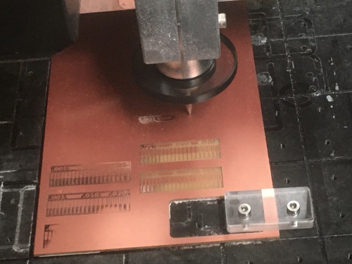
As the machine started milling it soon stopped even scraping the surface.
It was now clear that I had to operate on the flatness of the material, as clamping down the bottom corner had massively impacted on my Z axis.
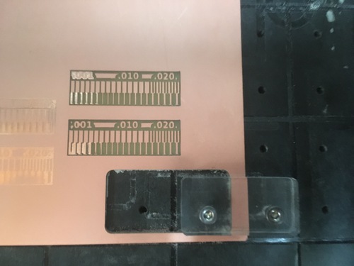
Test 7
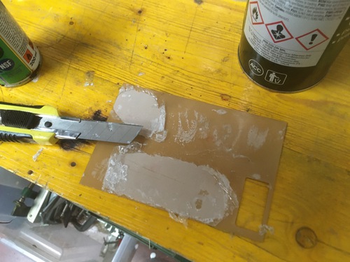
I used solvent and white spirit, with the help of a cutter, to remove the double sided tape.
I cleaned the material again using alcohol. I then stuck a new layer of double sided tape. This time I was extra careful.
Picture taken at a later time.
Lowered the Z axis by 0.01 (total from first light: -0.15). The machining didn’t produce any cutting. This meant the cleaning process really worked and the drill bit was no longer touching the material, showing that the material was now more strongly attached to the sacrificial layer.
Test 8
I so decided to reset the Z axis zeroing, using the probe and 10steps and 1steps increments. The first light appeared at -0.18mm from the last Z axis, which meant a total -0.33mm delta with the first ever light achieved with the probe before Test 1.
I then lowered the Z axis by 0.10 to achieve similar depth to Test 4, which was the first one to present white dust from the phenolic paper and had quite precise traces.
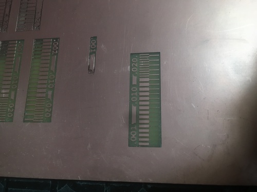
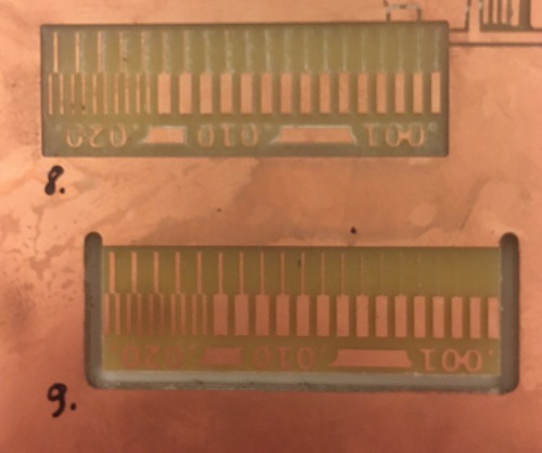
The result was alright.
Test 9
I decided to do an additional test step before cutting the outline with more depth to see how the traces would be affected. I lowered by 0.15 (total of -0.25 from “first light” since resetting the Z axis).
The result came too deep (therefore flared and less precise). I decided that I now had a fully flat material as the trace did not present gradients in test 8 and 9; I also knew I had a range of depths from “first light” that would give me decent enough results.
When I proceded to change tool and cutting, I realized my CAM was missing one side. I proceded to modify the original .png to obtaining all necessary cut lines.
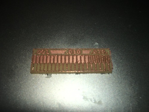
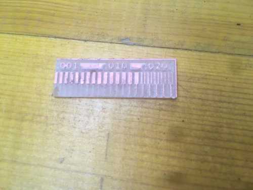
Test 10
Since I had changed drill bit after Test 9 I reset the Z axis. Because -0.25 from light in Test 9 was too deep, and -0.10 of Test 8 was acceptable, I lowered my Z axis at -0.10 from the light.
The result was more than acceptable, and did not require any filing or deburring.
Test 11
Since I now managed to get an acceptable result I decided to try againg at a slighly increased depth, in order to get better result in the lower end of the spectrum presented on the test object.
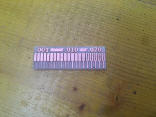
I therefore moved the Z axis from the previous setting, decreasing by 0.05 (for a current total from the first light of -0.05).
The result was, as I suspected, a little more precise.
PCB
Since I thought I was now quite comfortable with setting the machine and changing tools I decided to move on to the next step: machining my first PCB.
From the list of suggested programmers, I chose one based on an ATtiny44, as it would have been my first experrience stuffing a board I wanted to use one with reduced numer of pins.
The board I milled, stuffed and programmed is Ali‘s version of a ISP programmer, it is called “FabOPTIMUS”. Documentation can be found here.
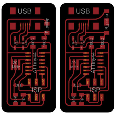
Among the two designs presented on the page, I chose the one featuring 1K+0.5K resistors.
CAD - CAM
I downloaded the images and put them in Fab Modules to generate the CAM.
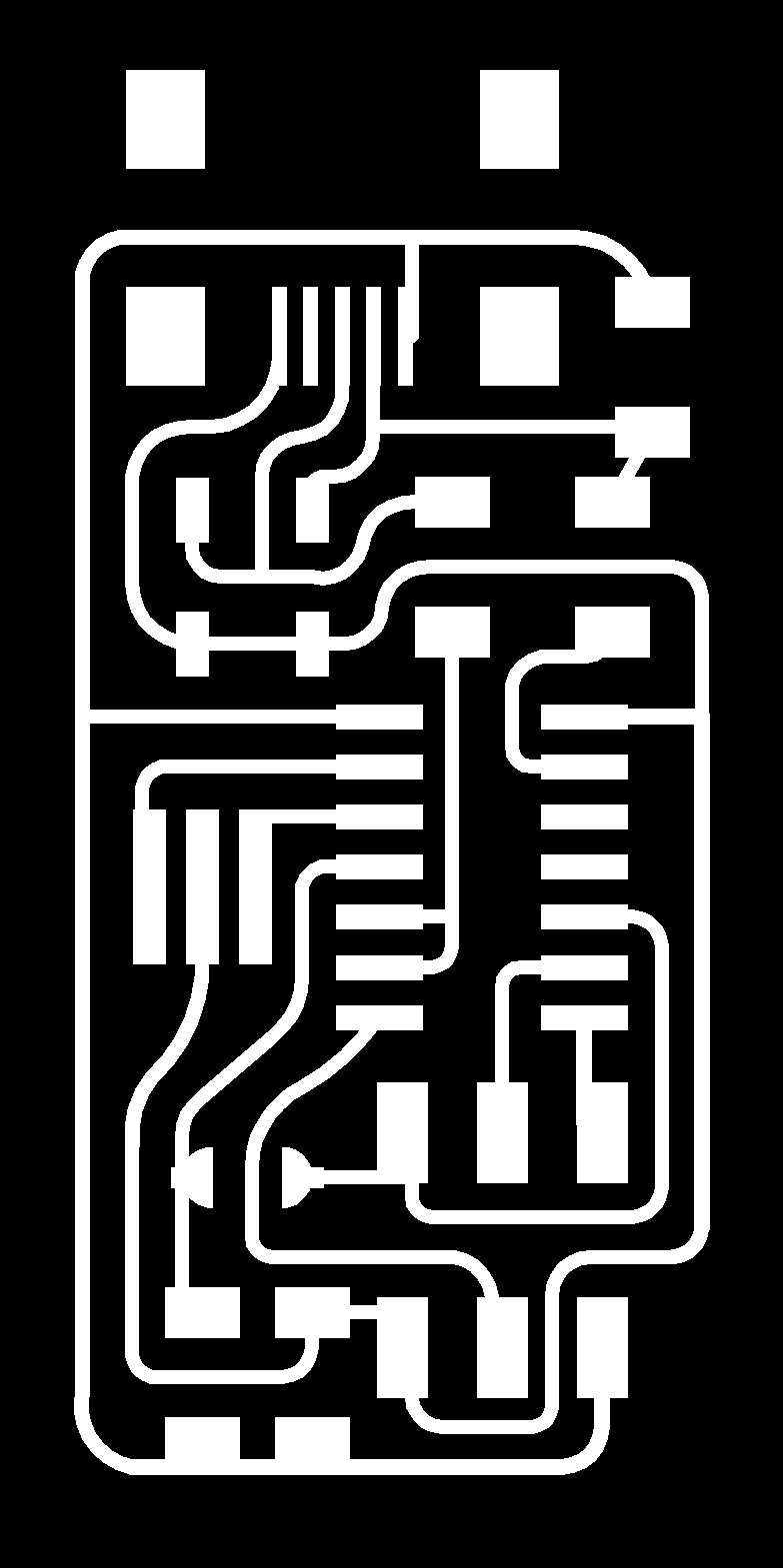
- Fab optimus traces

- Fab optimus outline
All documentation regarding Ali’s FabOptimus.
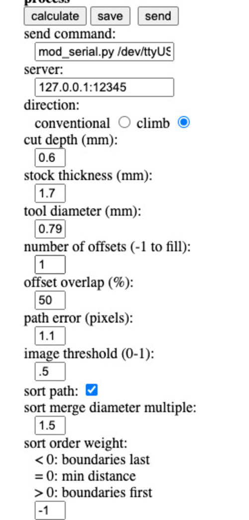
First I operated on the trace file.
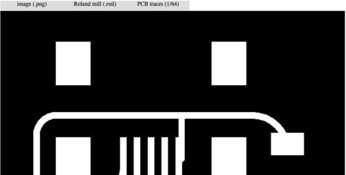
Selected:
-
input: image (.png)
-
output: Roland Mill (.rml)
-
process: pcb trace
- machine: MDX-40
- no offset from origin
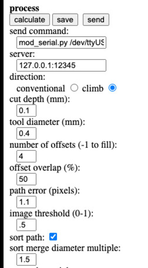
- direction: climb
-
cut depth: 0.1mm
-
offset: 4, 50% overlap
I then prepared the outline.
Selected:
-
input: image (.png)
-
output: Roland Mill (.rml)
-
process: pcb outline
- machine: MDX-40
- no offset from origin
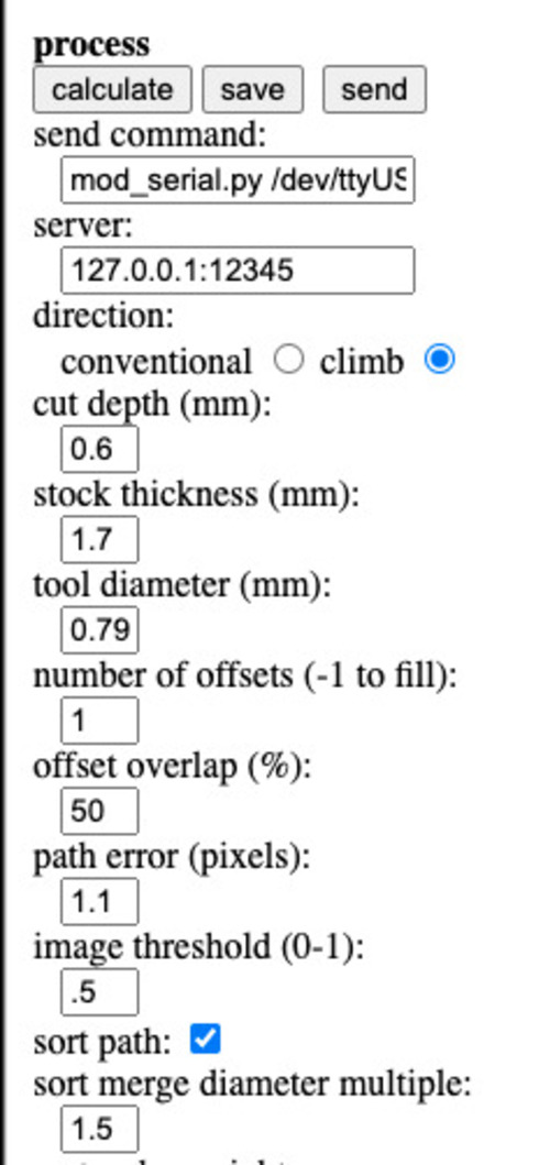
- direction: climb
-
cut depth: 0.6mm
-
stock thickness: 1.7mm
-
offset: 1
Machine preparation
I set the XY axis. The Z axis was out at -0.10 from the light in the first PCB, while I moved it at -0.25 for the second PCB I mantained the same piece of material as I previously managaged to make it nice, clean and flat during the previous round of tests.
I had the minimal cut speed fluctuation with the second cut, that unfortunatly presented a little more flare in the edges confronted with the other one (as the first cut was less deep).
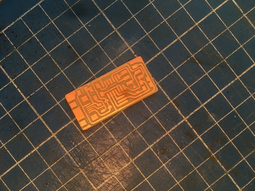
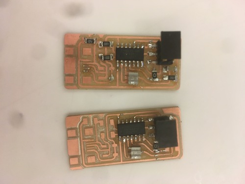
Results
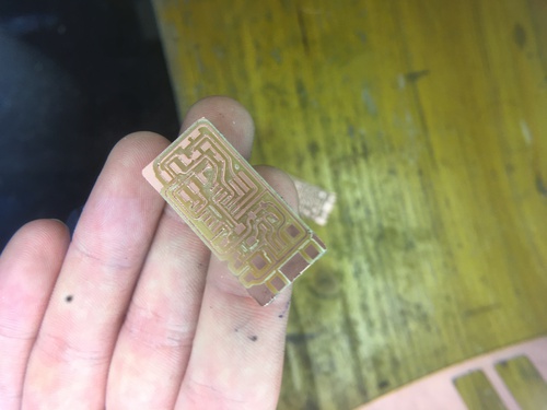
First PCB. Seemed pretty much right.
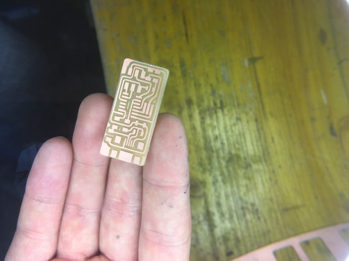
Second PCB. This one had some small areas that needed filing.
After having started soldering the first two boards, I slightly messed them up. Therefore I milled a third board that came out pretty much perfectly.
Finishing
After having machined the PCBs I proceeded to vacuum the dust, cleaned them under fresh water with a tiny amout of soap, proceeded to do a more in depth cleaning process with alcohol.
Deburring
As I didnt set the offset to -1 and used a 0.2mm drill bit, there were some extra traces in the bigger empty areas.
The second step of the finishing was using a small blade to do some deburring.
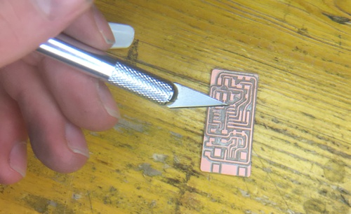
I only did this to the second PCB as it was less precise than the first, which I decided not to manipulated excessively, not to risk to damage it.
Filing
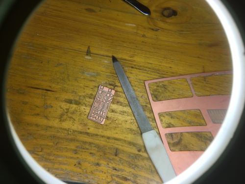
Once deburred, the copper traces still presented a few lightly flared edges. I decided to use a nail file I had brought in order to take these flares out.
This is how my PCB looked after the finishing process, ready to be stuffed, soldered and programmed.
Soldering
This was my first ever exprience soldering. I really enjoyed it.
I found it a quite calming routine and was very focused as I quickly discovered how it’s a metter of calm and precision.
The way I worked was to have in front of me a picture of the schematics and a fully built FabOptimus next to me that I could “copy”.
Bill of materials
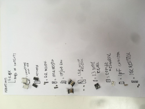
Among the two designs of the FabOptimus programmer, I choose the R_pullup=1.5K one.
The components included: - miniUSB connector
-
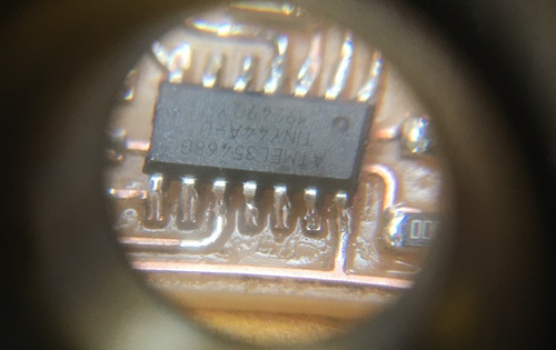
ATtiny44 microcontroller
-
0ohm resistor (to be removed once the board was programmed)
-
2 x 100ohm resistor
-
isp\smd 6 positions header
-
1.5k pullup resistor
-
2 x 3.3v Zener diode (we only had two left so i only included them on my final board)
-
20mhz resonator
-
1uF capacitor
-
10k ohm resistor
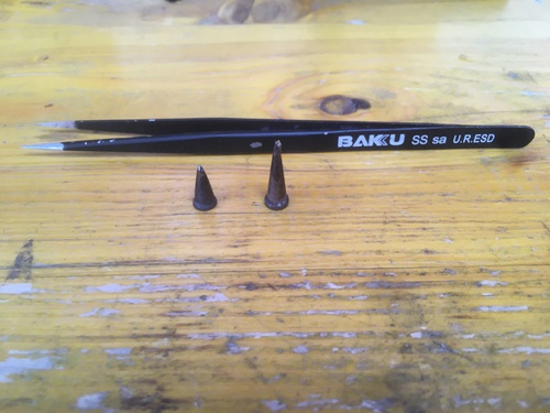
Preparation and tools
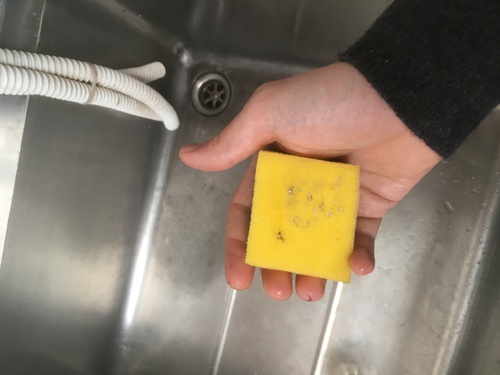
I kept to my left the soldering iron and sponge.
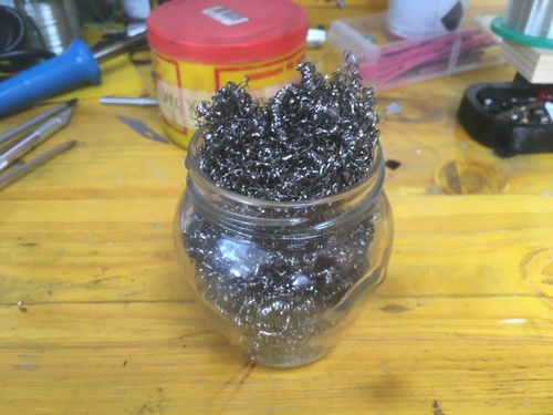
I also had a glass jar filled with steel wool for cleaning.
I used two soldering tips: - a larger one for most parts
- a smaller one that I used in the more crammed areas and to tidy up the messier soldering
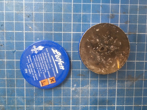
I used flux to tidy up where I had a lot of pins very close one to another: - around the ATtiny44
- in front of the USB connector
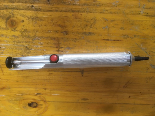
When I needed desoldering I attempted to use a vacuum.
Technique
As suggested during the lesson I began my soldering with the ATtiny44, from there on I moved around starting from the components that were smaller and closer to the centre, moving outwards. The USB and smd heard were left for last.
Being a clumsy fella and having a bit of trembling in my fingers (not to speak about my thumb that has lost all tactile sensitivity due to a sandwich making incident) I forced myself to take this process slowly and controll my breathing, taking breaks every once in a while to relax my carpal muscles and hand tendonds.
I soon realise that the practice that made me feel the most secure was to had a little bubble of tin on my soldering tip, gently place it on the trace, then grabbing the component with tweezers, I would warm the placed tin again to place the component. I would then solder the other side normally and tidy the first side.
I did not stuck my board with tape or held it with a rig as I preferred having the possibility to quickly move it around in order to get the best possible angle for each component.
It was vital to remember to correctly orientate both diodes and the ATtiny44.
Process
This was the first component I soldered onto the board. I did not yet used flux at this point.
The first to attempts had a few issues.
On the first one (above) I:
- soldered together the USB pins and didnt manage to desolder them correctly using a vacuum
- missplaced the 0ohm resistor and spilled molten tin all around it when attempting to move it
I frankly thought it was not that bad, keeping in mind it was the first ever circut I approached.
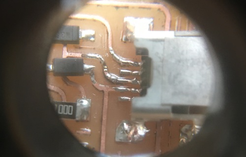
On the second one (below) I: - broke the trace underneath the resonator
- soldered the header just after the microcontroller (in order to test how I did that) as I had alrady broke the trace
At first I was convinced I could fix the trace, but as I tried to solder it back onto the board I fully detached it.
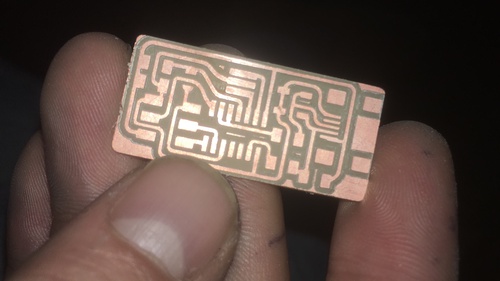
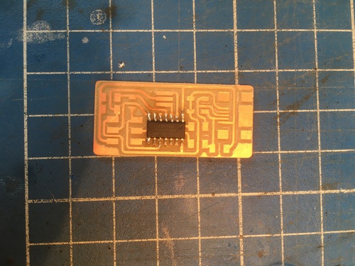
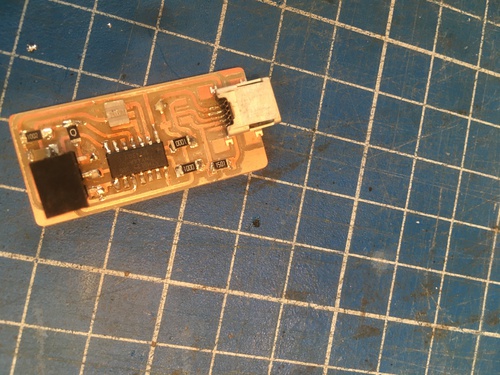
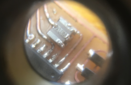
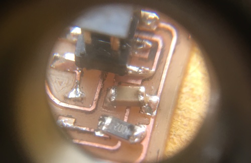
This is my third and final board. I was happy that as I was working on it I was feeling a lot more confident.
The result could have been neater and I could have cleaned the board better from machining dust, but all connections seemed to be working and I didnt have areas that seemed problematic.
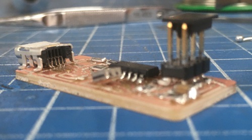
Hero shot
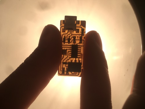
VERY VERY proud! This thing came out of my fingers! Splendid!
Testing
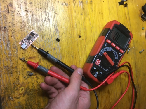
I used a voltimeter to check wether my connections were working. I followed the schematics I order to follow the traces and assure all was functioning correctly. I received a ping wherever I needed it to. I also tested I did not get a ping where it wasn’t supposed to.
Programming
It was now time for the final test. Would it work? Would it not? Was I going to start all over?
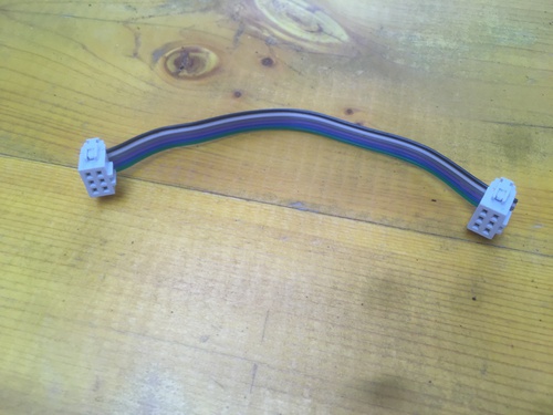
Btw the ribbon was also of my own making.
My tutor Antonio and I connected the my board to his ATtiny44 and to his laptop and he showed me the steps for it to finally become functional.
In the following comman lines the name of the computer will be his, but I was present at all times so that he could teach me the workflow and explain the coding to me as i knew pretty much nothing about it.
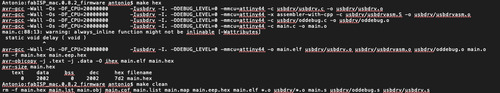
We first did a ‘make hex’ and ‘make clean’ so that Antonio could show me what kind of files would go in my FabOptimus and how they looked.

Repeated ‘make hex’.
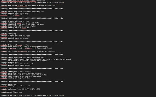
We did ‘make fuse’ in order to tell the microcontroller to use the external clock I soldered onto the board.
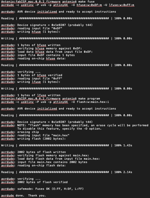
So far so good.
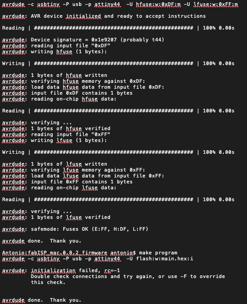
When it came to time do ‘make program’, a error came out, the one error I did not want to see: rc=-1. At first I was very worried I had to start all over, but something as simple as switching the ribbon the other way round solved the problem: I had connected it wrongly!.
We repeated the whole process and… it worked!
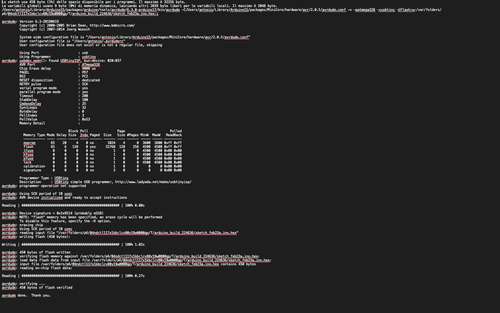
We did a simple test using my FabOptimus to program an Arduino via Arduino IDE and the board fully functioned. It was a very satisfying moment.
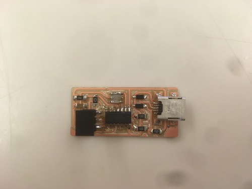
I was now time to desolder the 0ohm resitor.
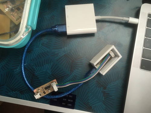
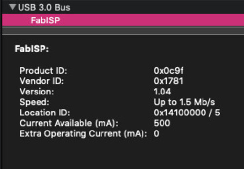
Here is a picture of my laptop recognising the programmer, it was a great feeling to see this.
Group Assignment
We mainly use our loyal Roland MDX-40 in order to mill circuit boards. We also generally use FabModules to generate CAMs.
Our design rules are generally the following:
- minimum space between traces is 0.4mm, which is almost 16mil
- in order to engrave our phenolic paper we set the spindle RPMs to 15‘000
- we use a 0.1mm cut depth for the trace, only one stepdown is necessary
- we use instead a 0.6 cut depth for outlines, because the stock is 1.7mm thick, outline jobs take 3 stepdowns
- the speed is about 2mm\s for engraving
- this speed drops to 1mm\s for outline cutting
- sometimes is helpful to “trick” FabModules by slightly reducing the tool size (to 0.38 or 0.36), because sometimes the software does not recognise spaces in between parallel diagonal lines
- we use 0.2mm or 0.4mm 30° V-bits for the traces
- we use a 0.79mm flat mill end for outline cuts
Task list
-
[x] Characterized CNC machine
-
[x] Milled tests
-
[x] Milled Programmer boards
-
[x] Stuffed and soldered the board
-
[x] Programmed the board
-
[x] Use the programmer to program another board