Week 5
3D Printing and Scanning
This week, fro 3D printing and scanning, we had both individual as well group assignments regarding the same. The group assignment was to test the design rules for our 3D printer. The Individual Assignment was to design and 3D print an object that could not be made subtractively and 3D scan an object
I started by understanding some of the technical terms related to the software.
Layer height is the one which results the surface finish quality of the print it can be vary from 0.06 to 0.3 that depends the printer and it's hardware precision.
Infill is defined how much inside fill needs to make the print wright less or rigid while printing this infill print quality can be adjust from 0 to 100 % .There are various types of Infill pattern structure available for making the print structure more mechanical properties.
Cooling is a feature that helps to cool the printed part immediately after the print material came out from the nozzle which can be helpful while printing angled objects,bridges..etc.. .It is possible to adjust the fan speed from 1 - 100% depending on the print material cooling time we leaving it as 100% default for PLA.
Support is used for printing horizontal or angled object in mid air without touch ing the print bed .So the Printer will do thin wall pattern as a support structure beneath the model or part to be printed .The support can be removed by hand or with helps of some tools like knife,nose pliers ..etc..
Build Plate Adhesion: If the print is too small it wont be stick to the bed till the printing or the print bed finish Isn't that good ,In those case this feature can help us to give a Adhesion options like a 'Brim' of a tree which hold the print part without falling of the bed while printing. We selected 'Brim' for this print which is totally unnecessary for this model.
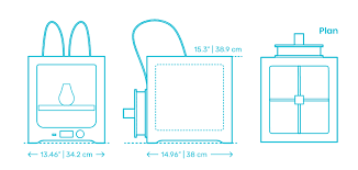
We use the Ultimaker for 3D printing.
Individual Assignment
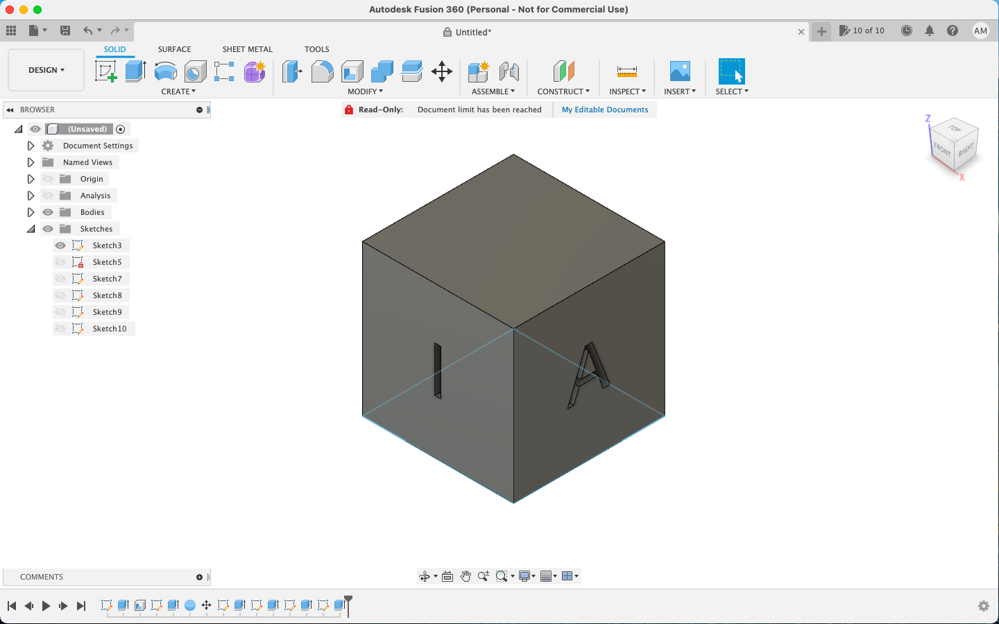
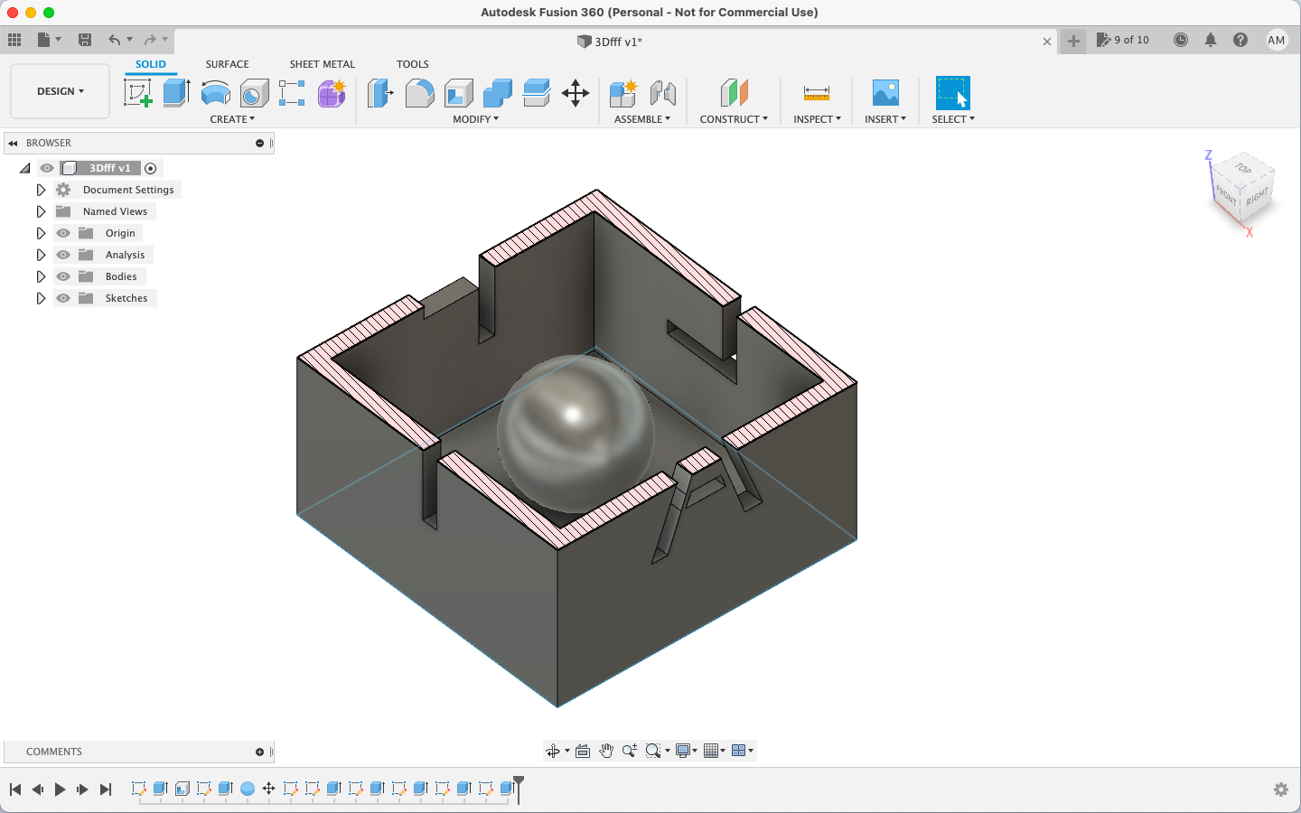
For the assignment, I wanted to do something simple yet different. Since the challenge was to make something that cannot be made without subtractive method, I spent almost a day figuring out what to make and every idea I came up with was either possible with subtractive method or is too complex and would take too long with the machine. So I decided to make a cube with a ball inside and letters form my name on the walls.
I designed the cube in Fusion 360 applying parameters.
The original file for the same can be downloaded from here
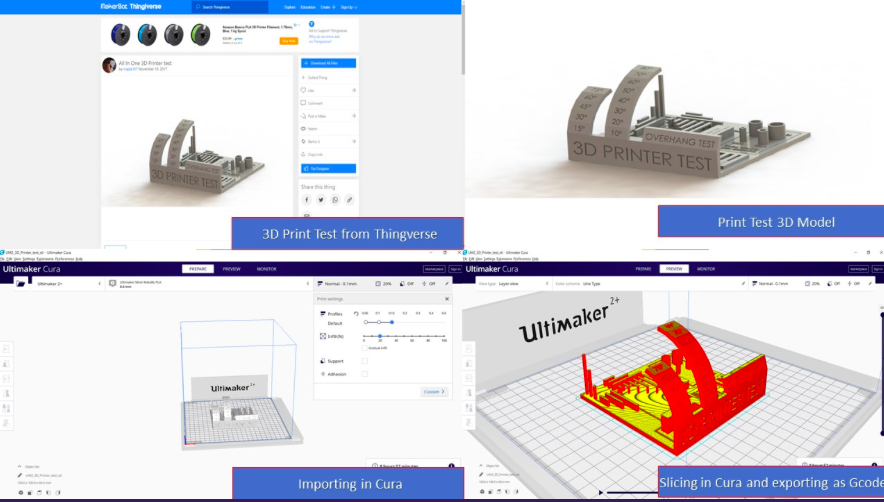
Once that was done, I installed Cura for Ultimaker and opened my design file in it. I made some slight changes on there before printing.
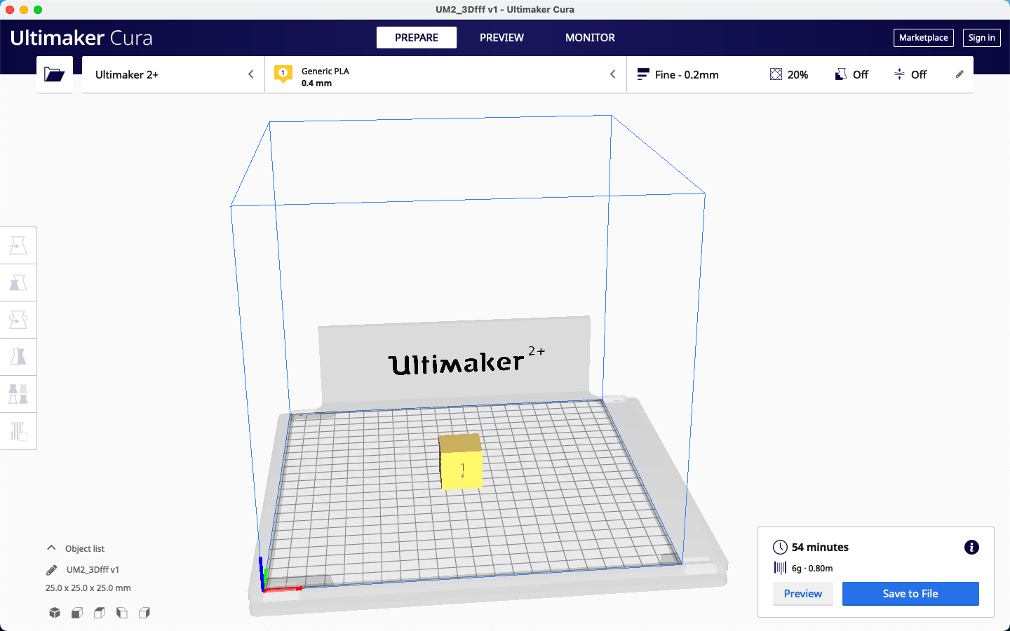
The slicing parameters used for the same were as given below:
Layer Height- 0.2mm
Wall thickness- 0.8mm
Infill pattern - Lines with 20% Infill
Print Speed- 30mm/s
Support type- Line
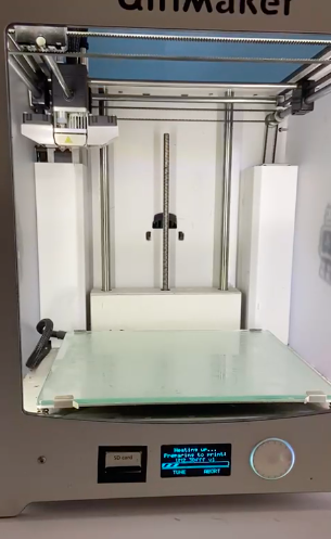
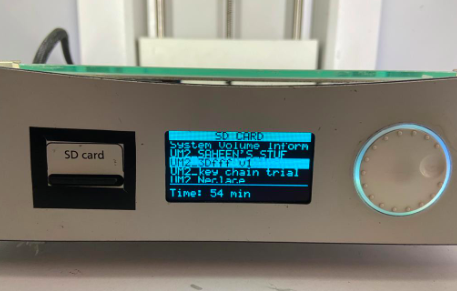
I then copied the file to the SD card, inserted the SD card into the machine and selected my file by turning the knob.
I then levelled the bed of the ultimaker and then loaded the design to the printer and started printing.
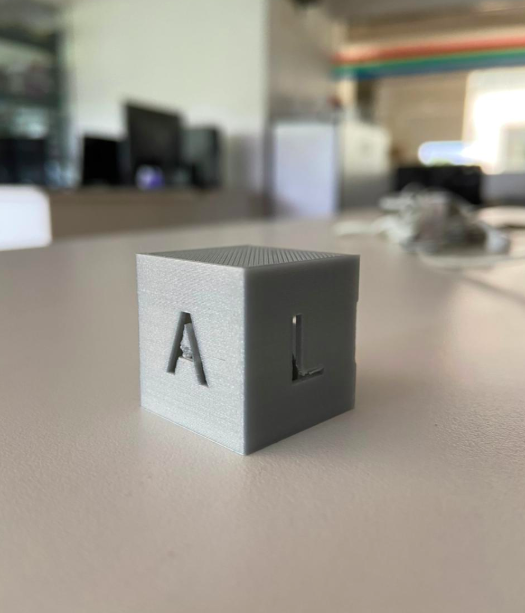
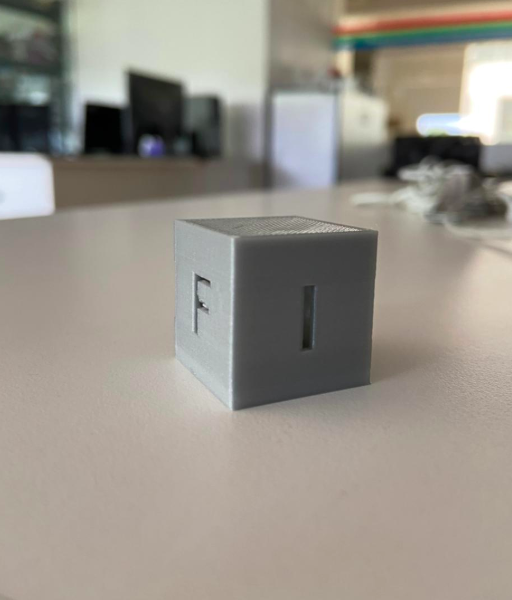
Once the printing was completed, the end result i got was this!
Group Assignment
Different 3D printing processes have different capabilities and different design restrictions. In this assignment we will talk about key design considerations that apply to all 3D printing processes. Understanding the 3D printer's limitation is important because this will reflect on the actual print quality of our prototype. Inorder to test the capability, we have downloaded a test print model from thingiverse and is shown below with the test parameters.
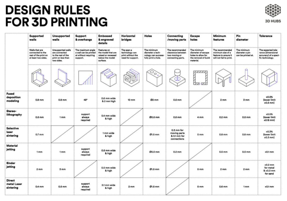
The following tests were performed with our printer and it met our expectations.
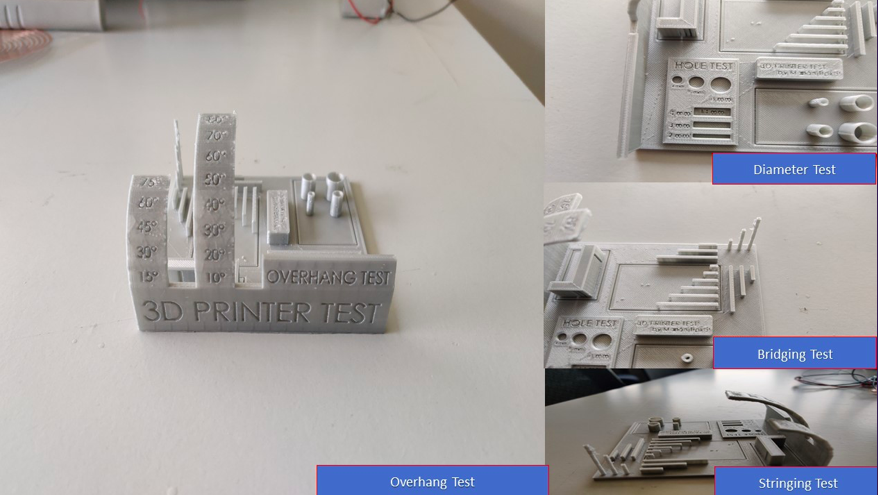
The Overhang :
This test allows you to know to which angle our printer can print without the need of a support ! Usually, overhangs up to 45° can still be printed without loss of quality. That’s because any layer in a 45° overhang is mostly supported by the layer beneath. In other words, each new layer has enough support to remain intact and to make printing possible. However, anything past 45 ° approaches the horizontal and becomes difficult to print. Such overhangs are prone to curling, sagging, delamination, or collapsing. Exceeding 45 degrees means every new layer has less of the previous layer to bond with. This translates to a poor quality print with droopy filament strands.
What we got: starting from 45° the quality of the printing started to get so saggy
The Bridging test:
Bridging is the printer's ability to print a layer between gaps in lower layers without support, essentially printing over thin air, creating a "bridge". It is very important that your printer can properly bridge, because many prints require some bridging.
What we got: the quality of the bridges looked perfect except the last one.
Wall test:
This thing allows you to test the thickness of the wall along X and Y axis inorde to check the accuracy
What we got: For X wall we got 1.8mm instead for 2mm and 1.8mm for Y wall instead of 2mm.
Cylinder test:
This thing allows you to test the accuracy of your printing process and to determine the optimal clearance between moving parts (e.g. hinges).
What we got: We got 0.3 mm as wall diameter, for 4mm outer dia cylinder we got 3.6mm, 6mm outer dia cylinder we got 5.6mm, For 8mm cylinder we got 7.6mm as outer dia and for 10mm we got 9.6mm as outer diameter
Hole test:
To see how closely a final 3D printed hole measures can be, compared to its digital model. The values of the holes were 4,6 & 8mm.
What we got: For the 4mm hole we got the value as 3.95 which is almost accurate. For 6 mm hole the value was 5.95mm and finally for 8mm we got 7.95mm. The X axis values were found more accurate than Y Axis.
Rectangular Hole Test:
To see how closely a final 3D printed rectangle measures can be, compared to its digital model. The values of the holes were 4*14, 3*14 & 2*14mm.
What we got: For the 4*14 mm rectangle we got values as 4.08*13.85. for 3*14 rectangle we got 3.08*13.85 and finally for 2*14mm rectangle we got 2.08*13.85 as value
The credits to the above details of the group assignment goes to my colleague Abhinav Ajith
3D Scanning
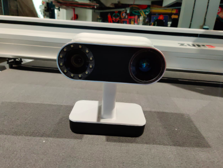
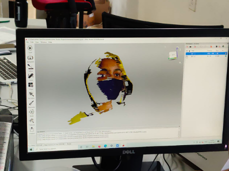
For 3D scanning, we have an Artec Leo in our lab. It is the first 3D scanner to offer onboard automatic processing, Artec Leo is able to provide the most intuitive workflow, making 3D scanning as easy as taking a video. As you scan your object, you can see the 3D replica being built in real time on Leo’s touch panel screen. You can also rotate the 3D model, check if you have captured all areas, and fill in any parts you may have missed. To start and understand the scanning part, as a group training, we scanned a colleague. She was scanned using the 3D scanner.
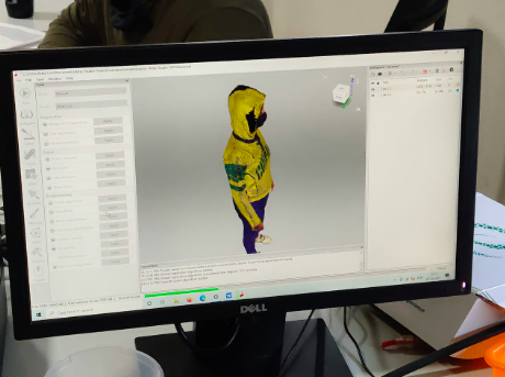
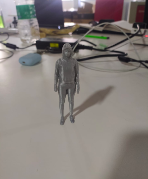
Once, the scanning was done, we proceeded to print her using the ultimaker.
The final result we got was a miniature replica of her.
My Assignment
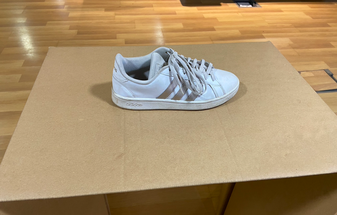
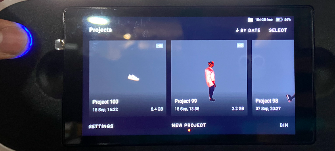
For my assignment, I decided to scan my shoe and see how it turns out. For this, I placed my shoe on an even plane surface without any distortions.
Then I turned on the scanner and opened a new project and scanned the plane surface to set reference and then started scanning the body as the scanner said it is ready to scan.
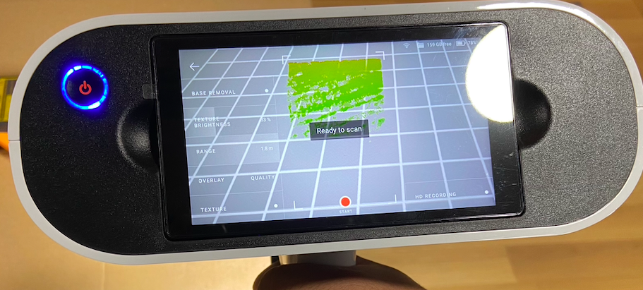
I started scanning by moving around the shoe in a controlled manner.
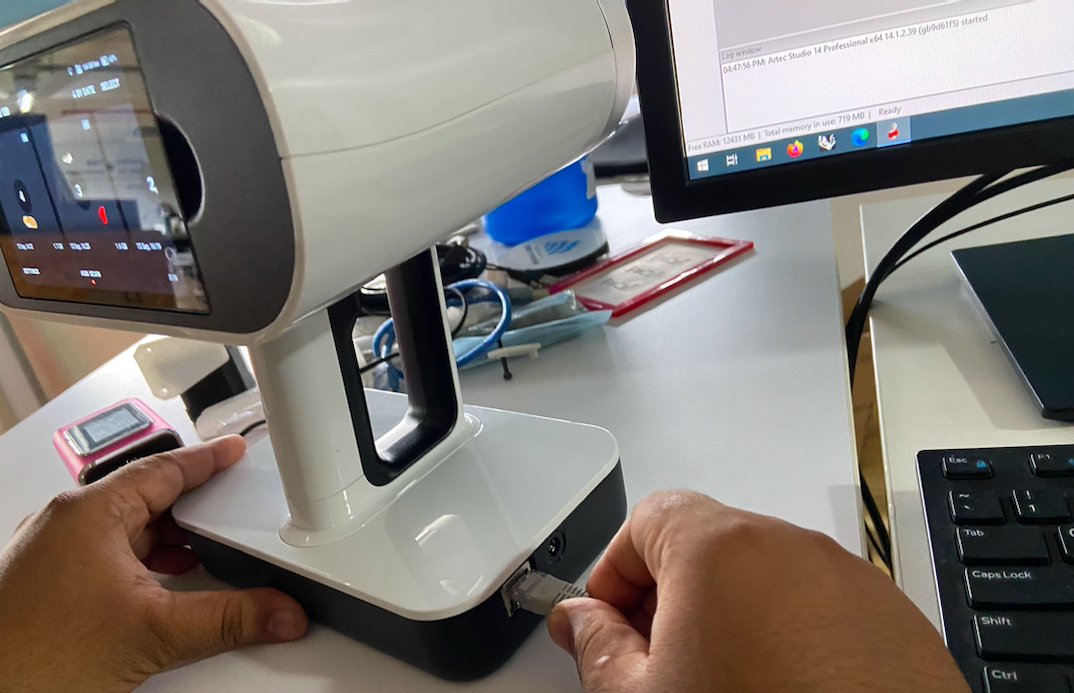
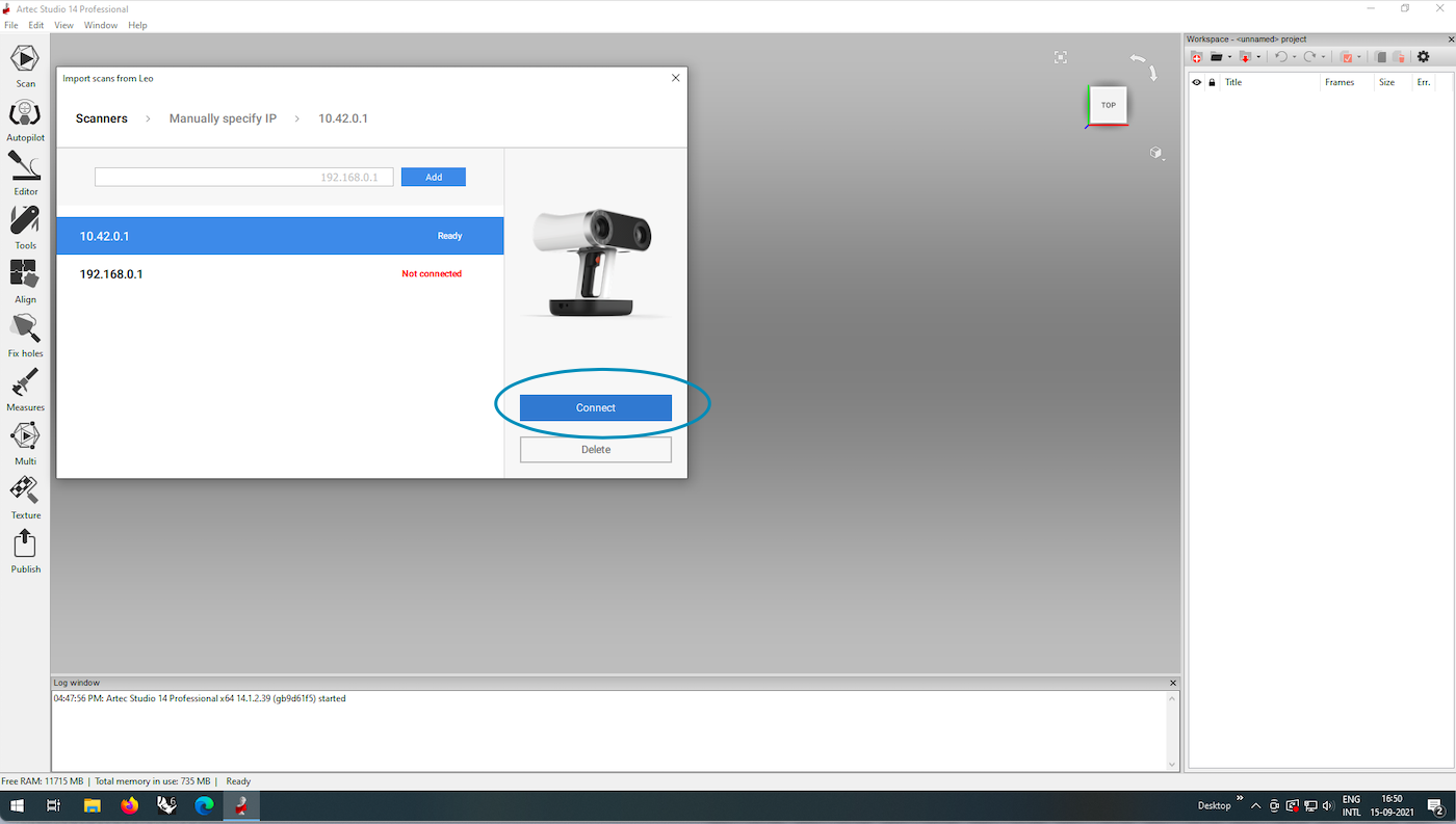
Once the scanning was completed, I connected the scanner to the computer to check the scan in the software.
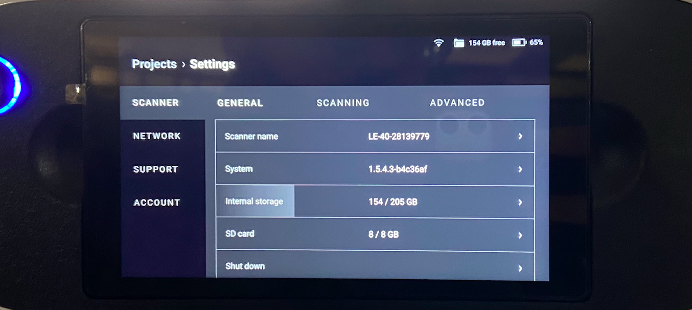
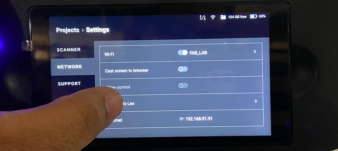
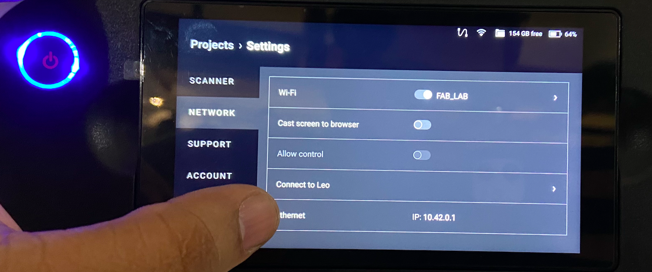
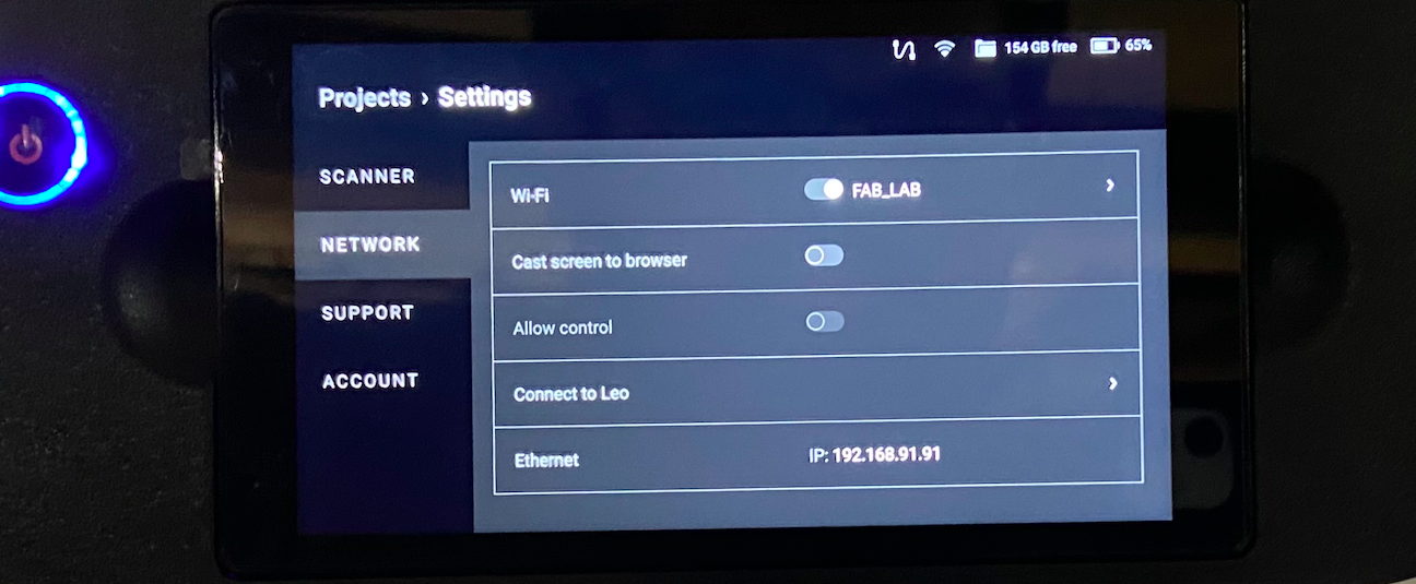
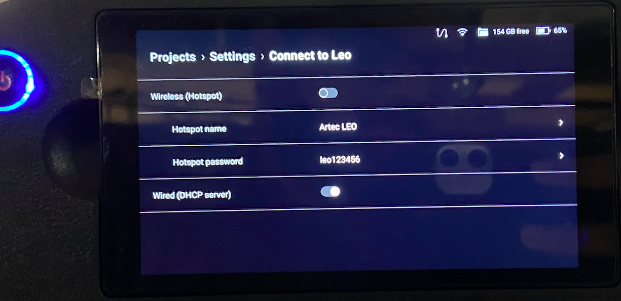
After connecting, I connected it to the wifi network in the settings. SHown below are the steps to follow.
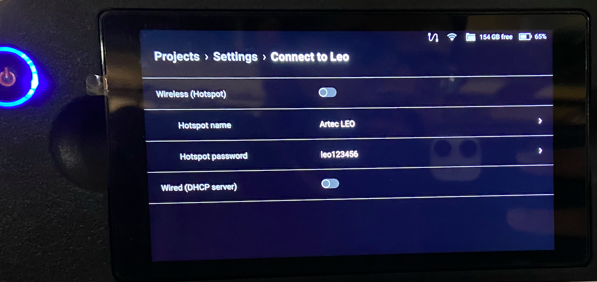
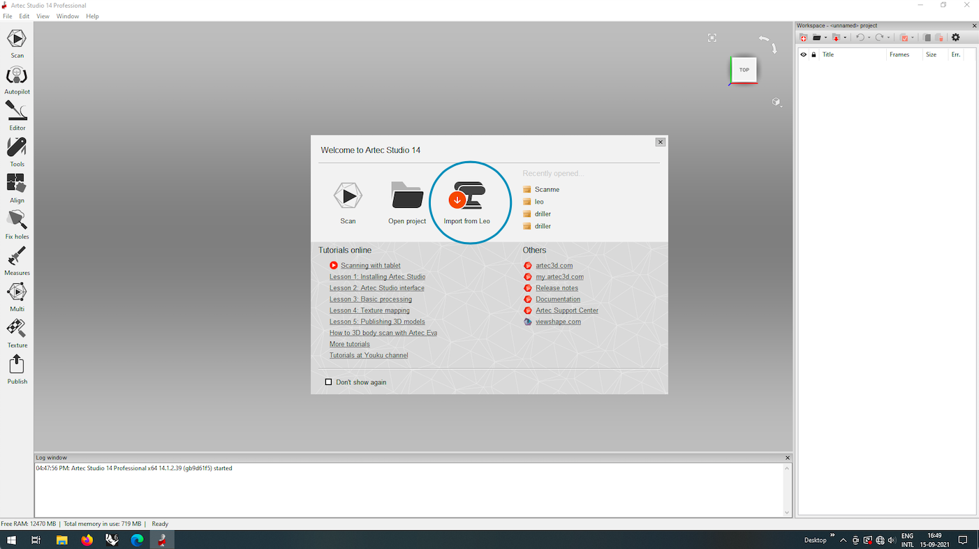
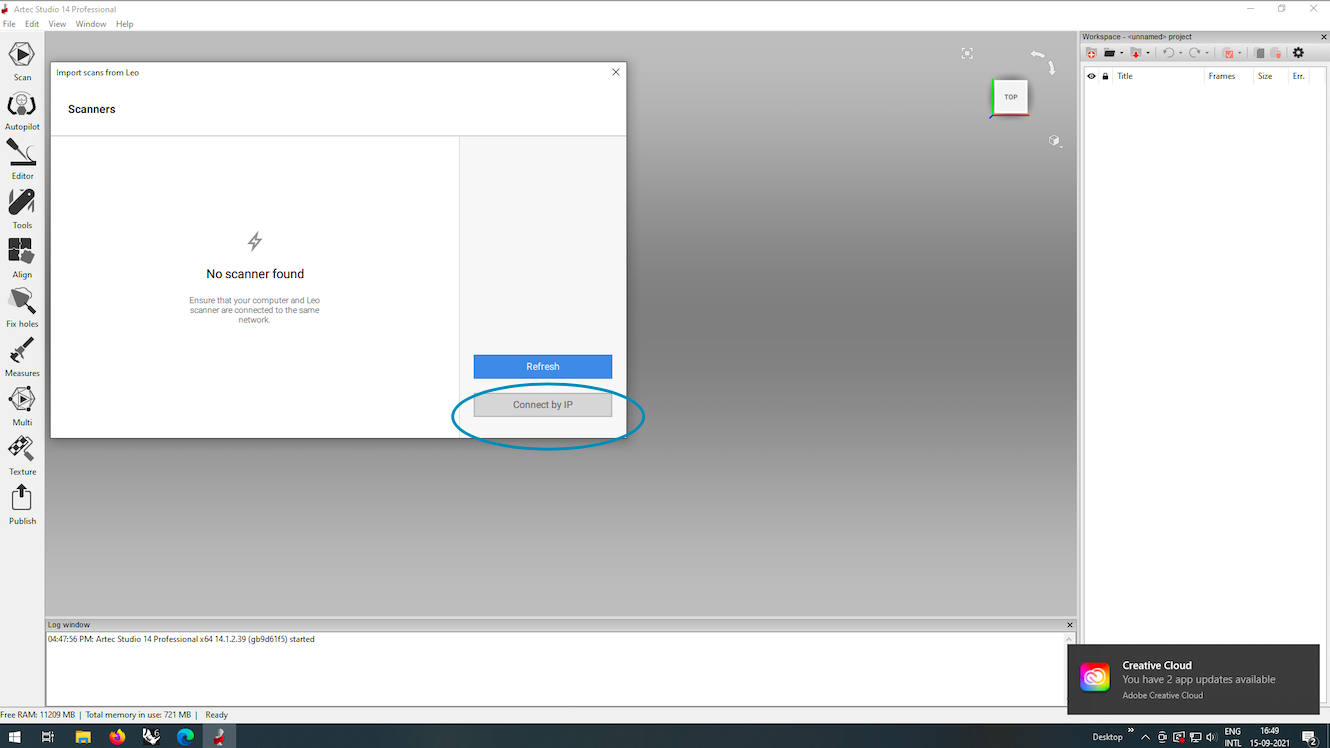
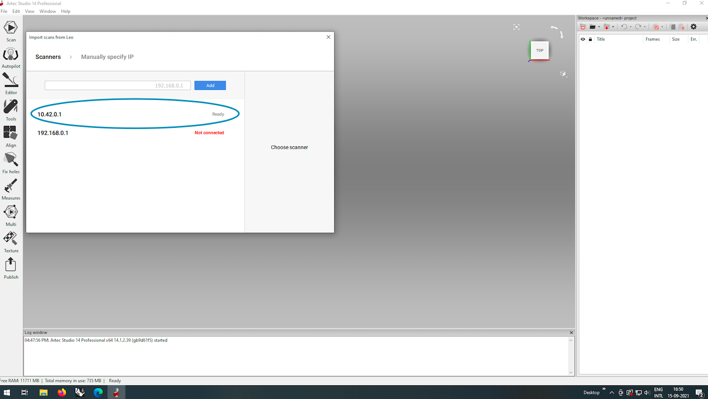
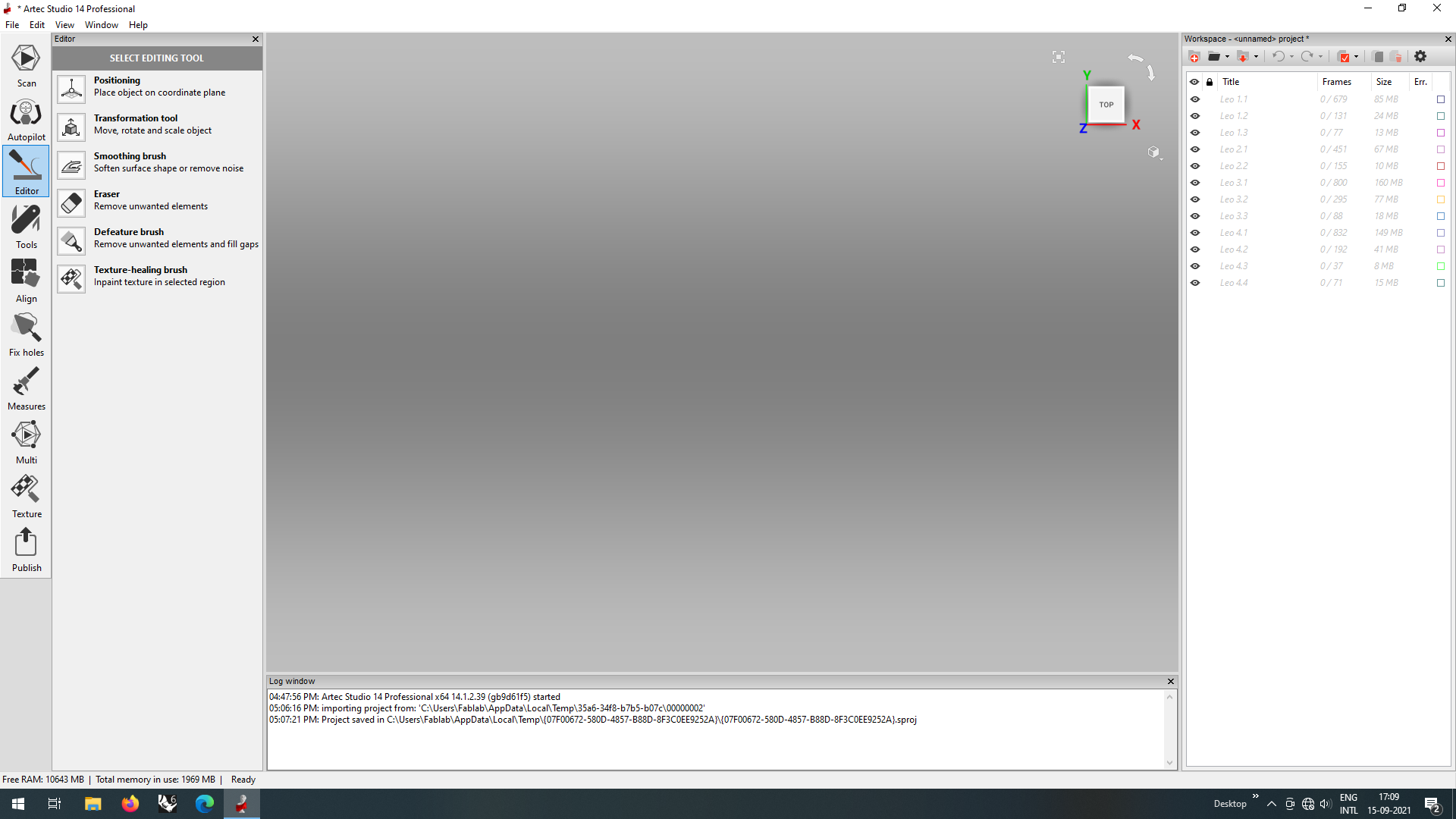
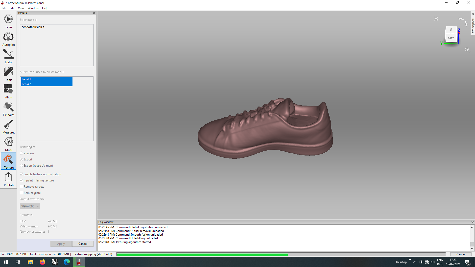
Once connection was established, I opened the editing software for artec to edit my scan. But before that I had to connect the device with the software. For that, I did the following steps
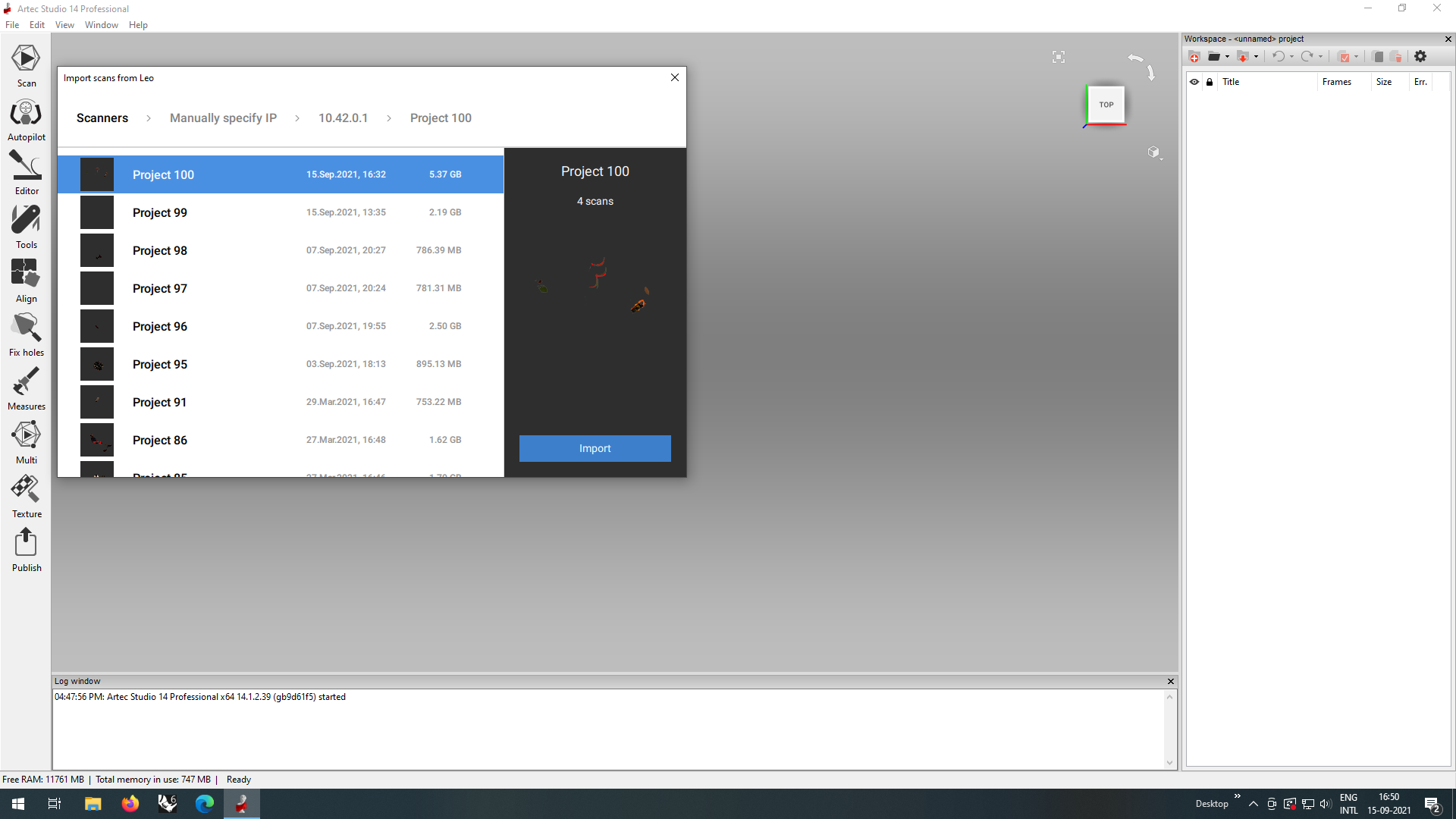
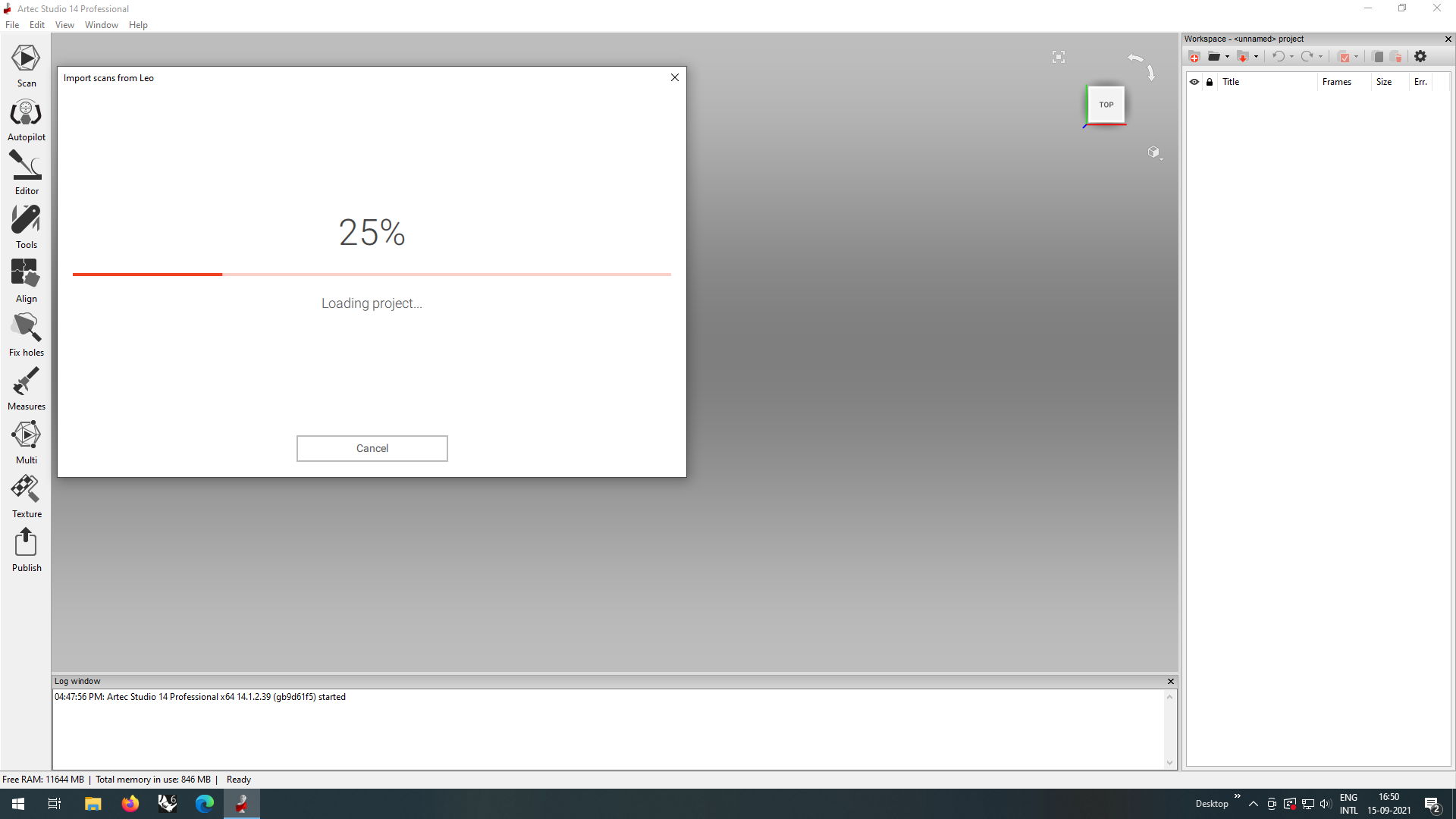
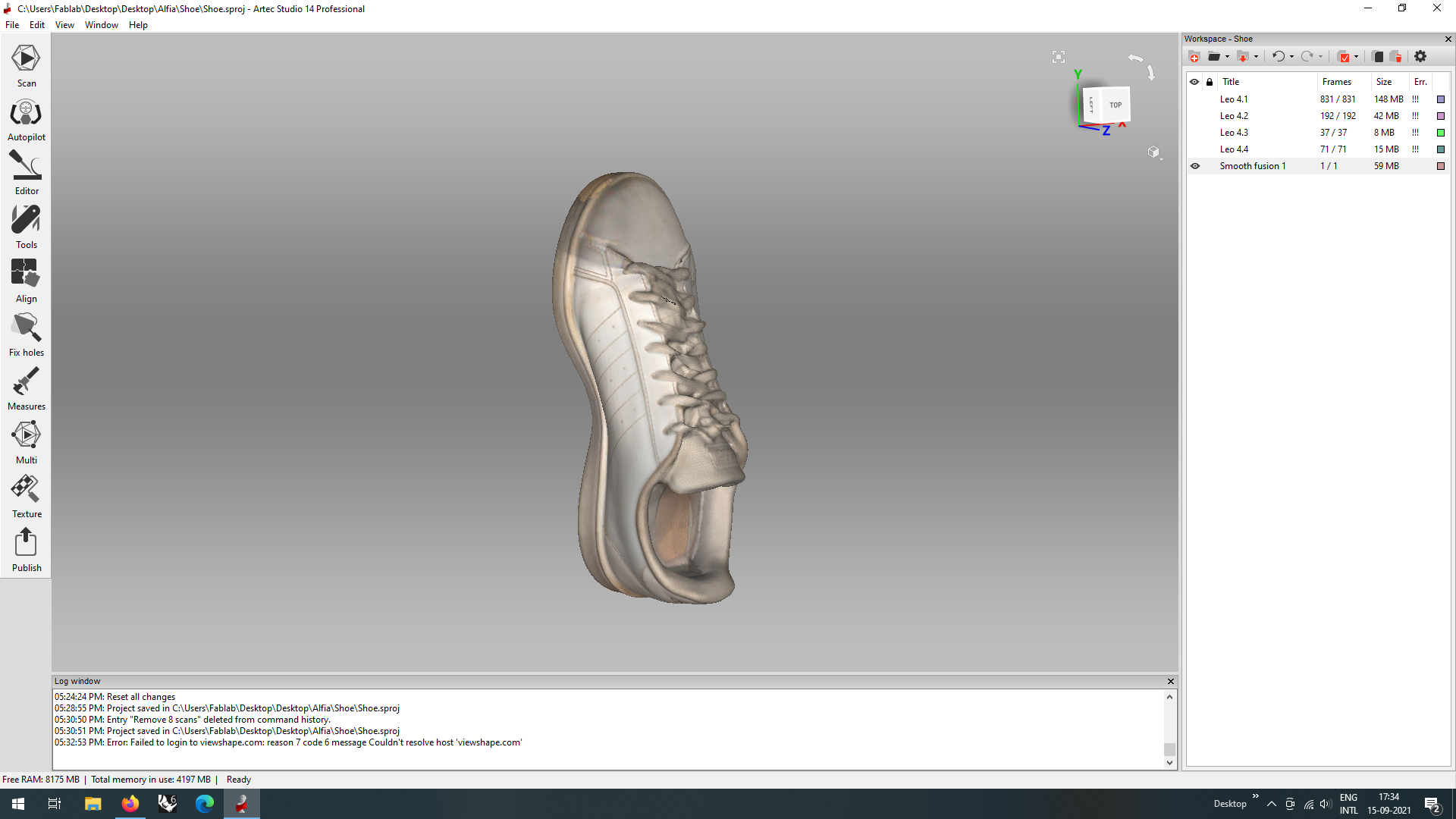
Now, I selected and opened my project on the software
They offer an autopilot edit mode, where the software automatically fixes minor errors and fix the scan as per a few details that you provide. But this eed not work for every scan. When it came to my scan, I had used a shoe and there were a lot of problems, for example the shoe lace being a non rigid body, the cavity of the shoe, etc. So I decided to try both and see what works best for my scan.
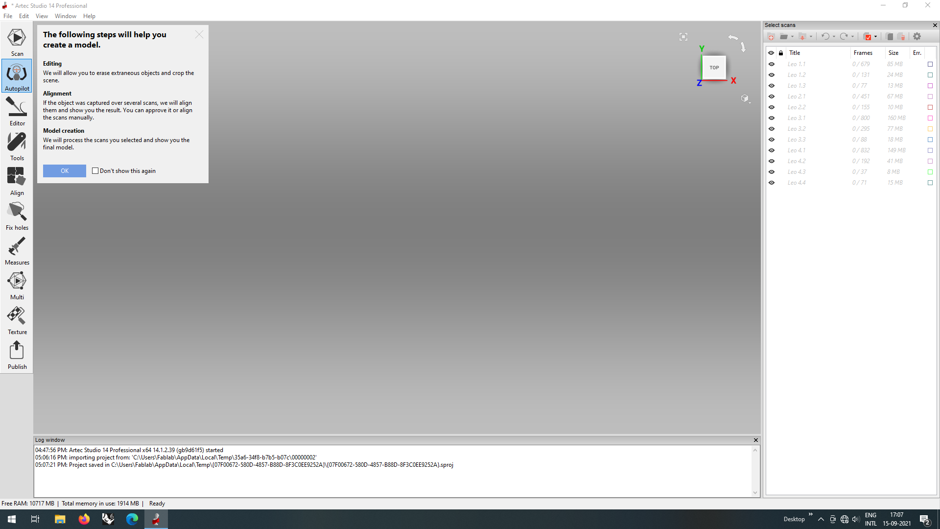
Autopilot Edit
For this, initially we have to answer a few questions that the software asks to optimise the scan.
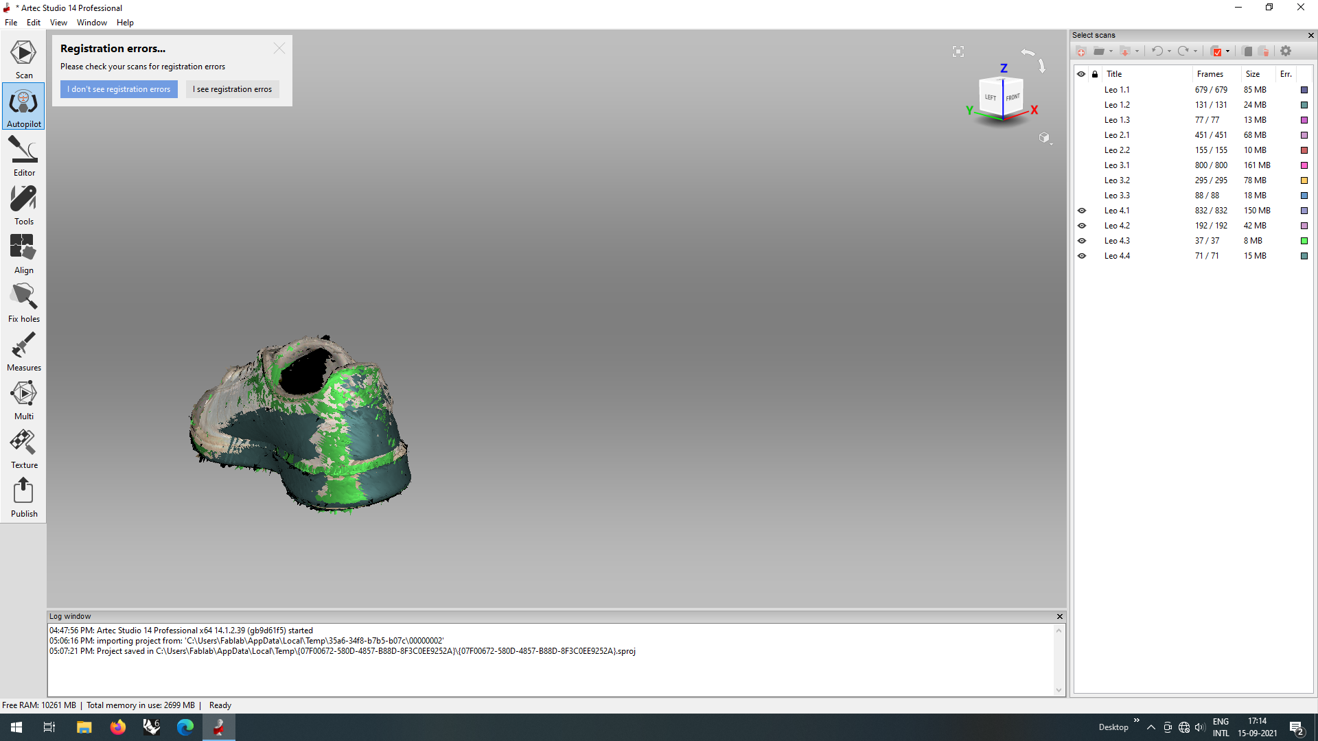
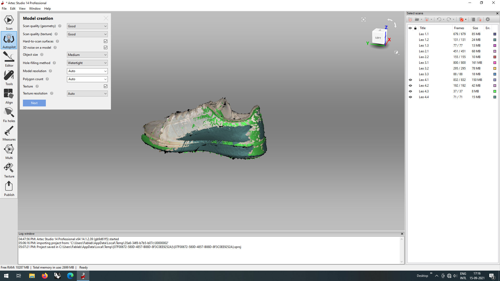
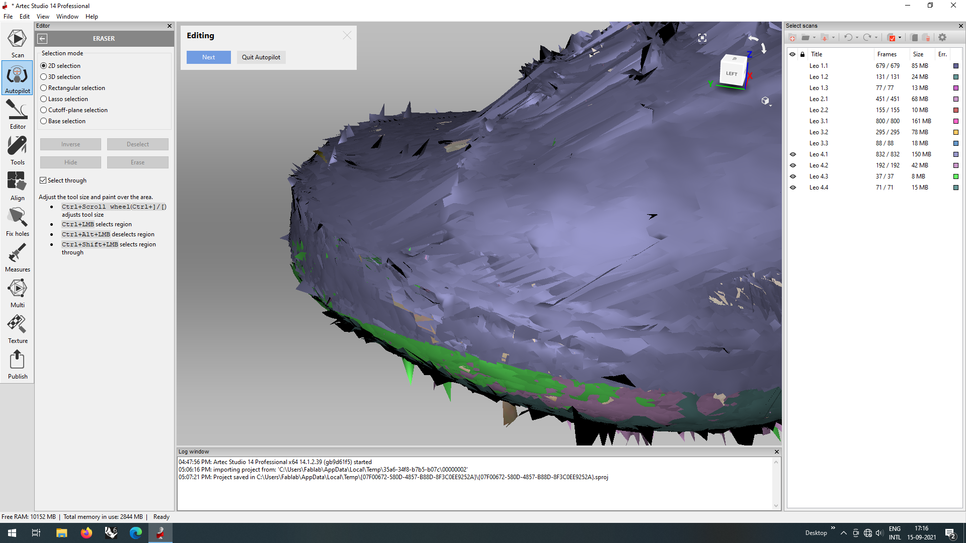
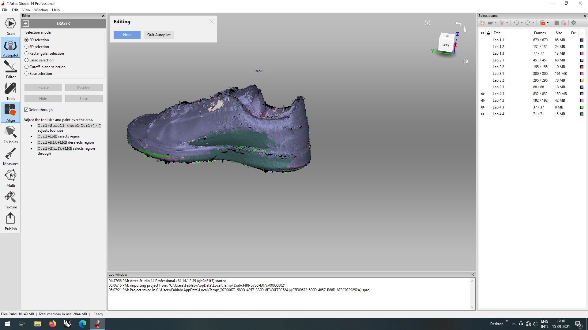
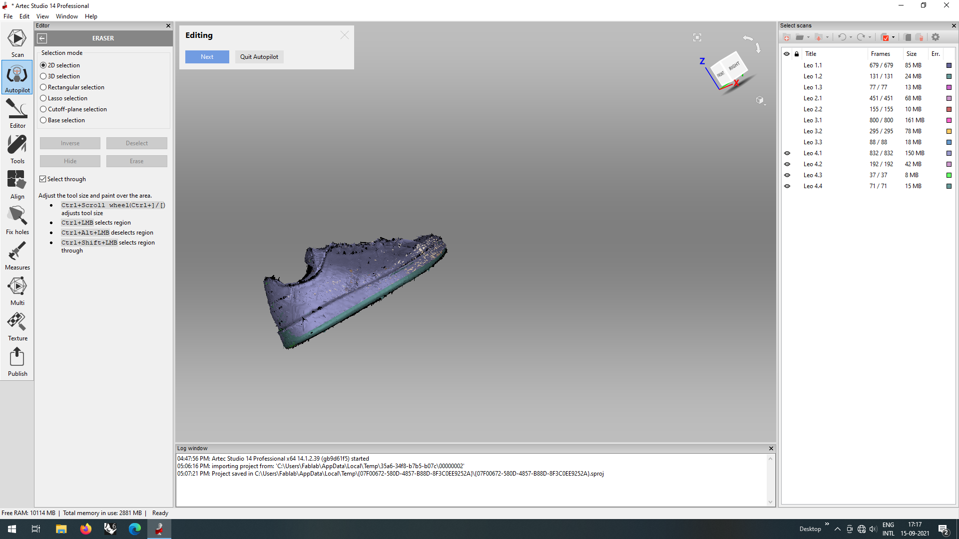
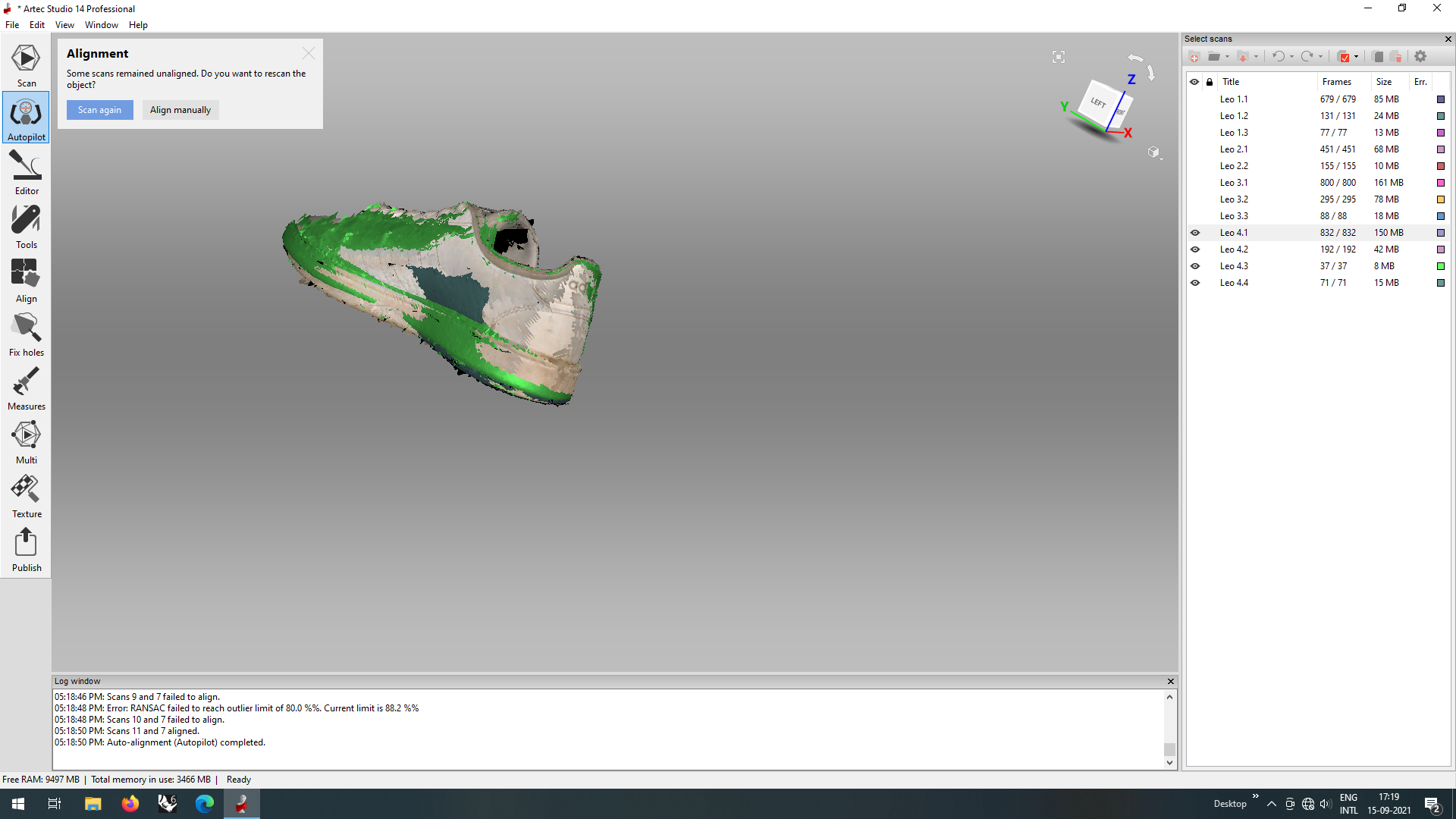
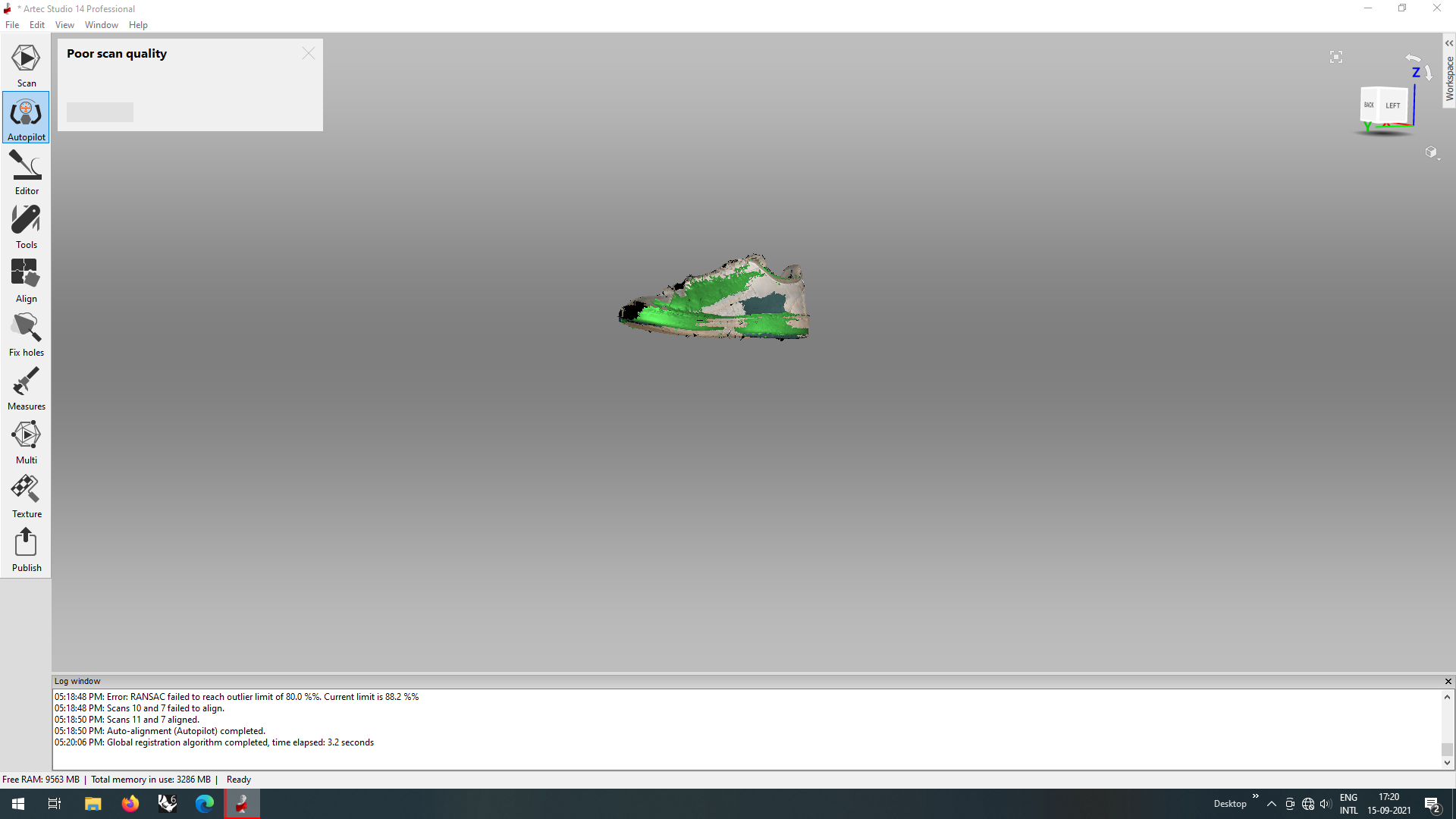
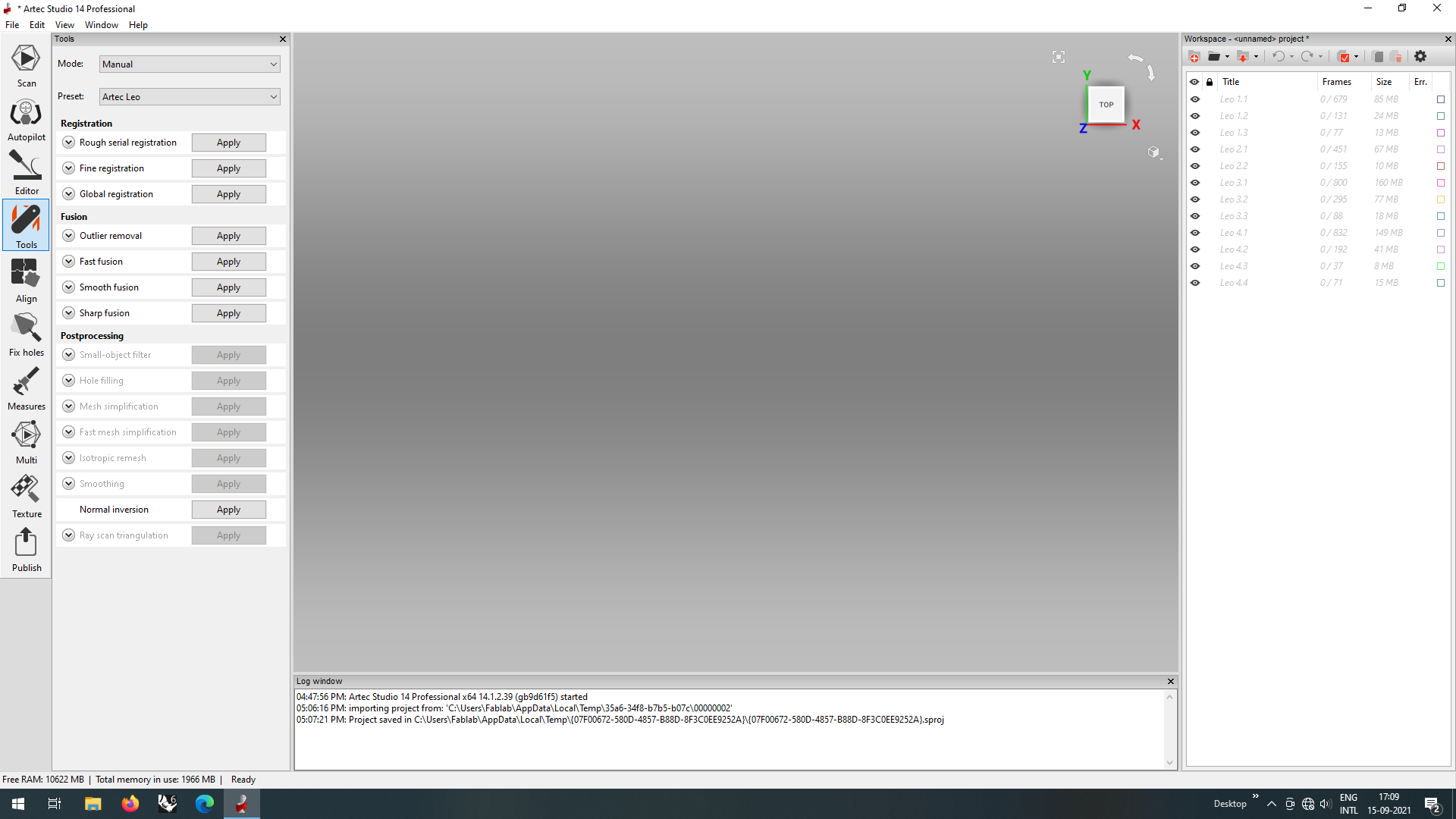
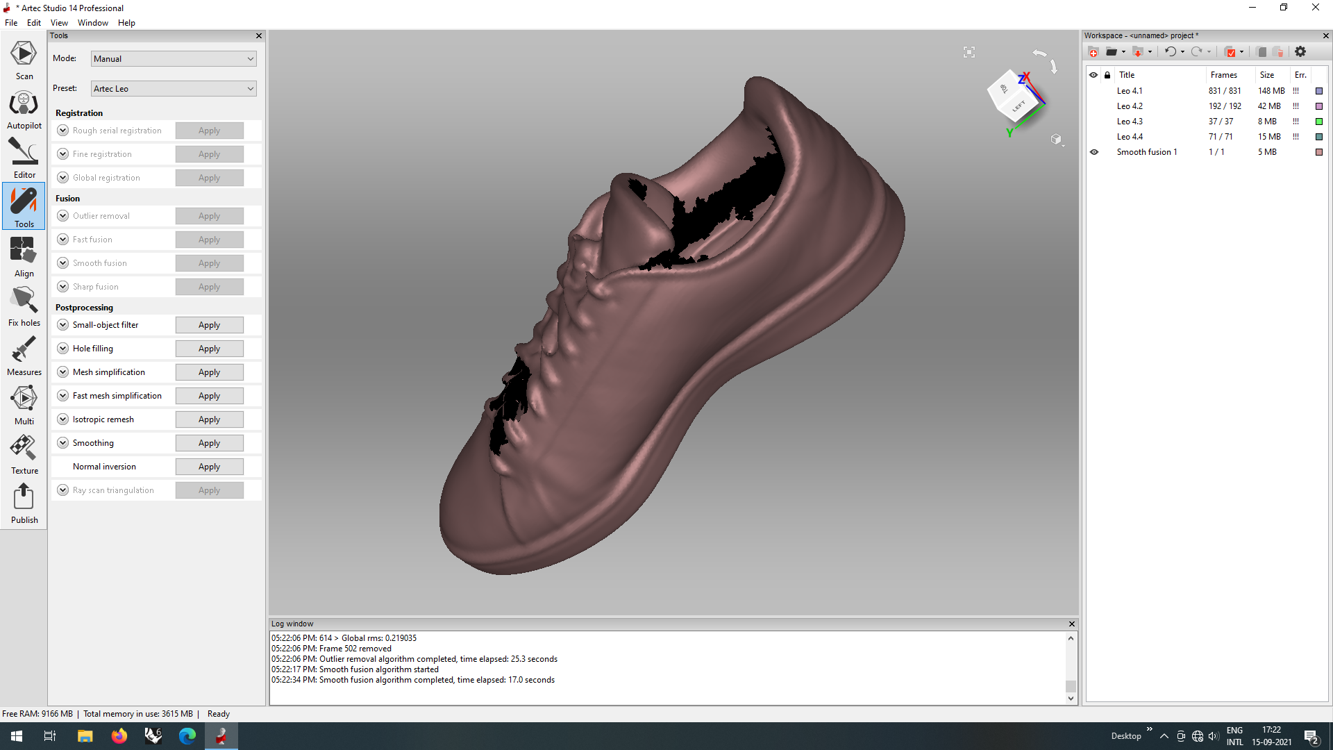
While the autopilot edited, it mentioned that the scan quality was poor, so i got out of the autopilot mode and edited a few things manually, fillings bits and gaps
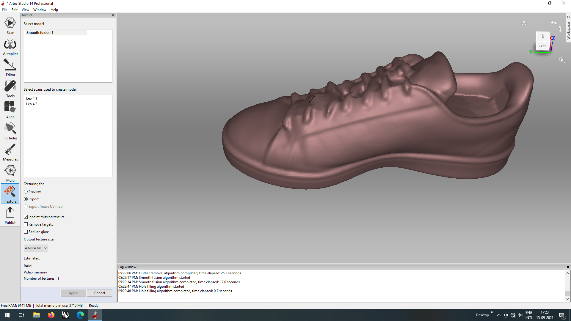
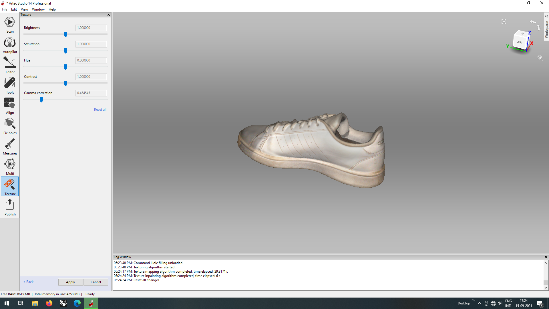
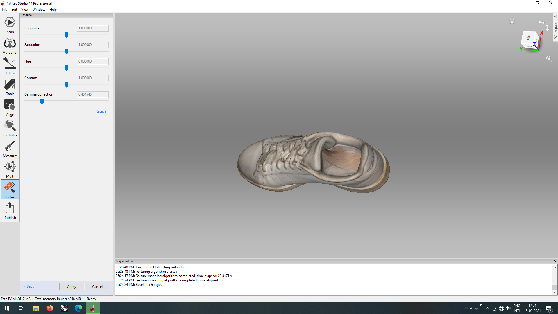
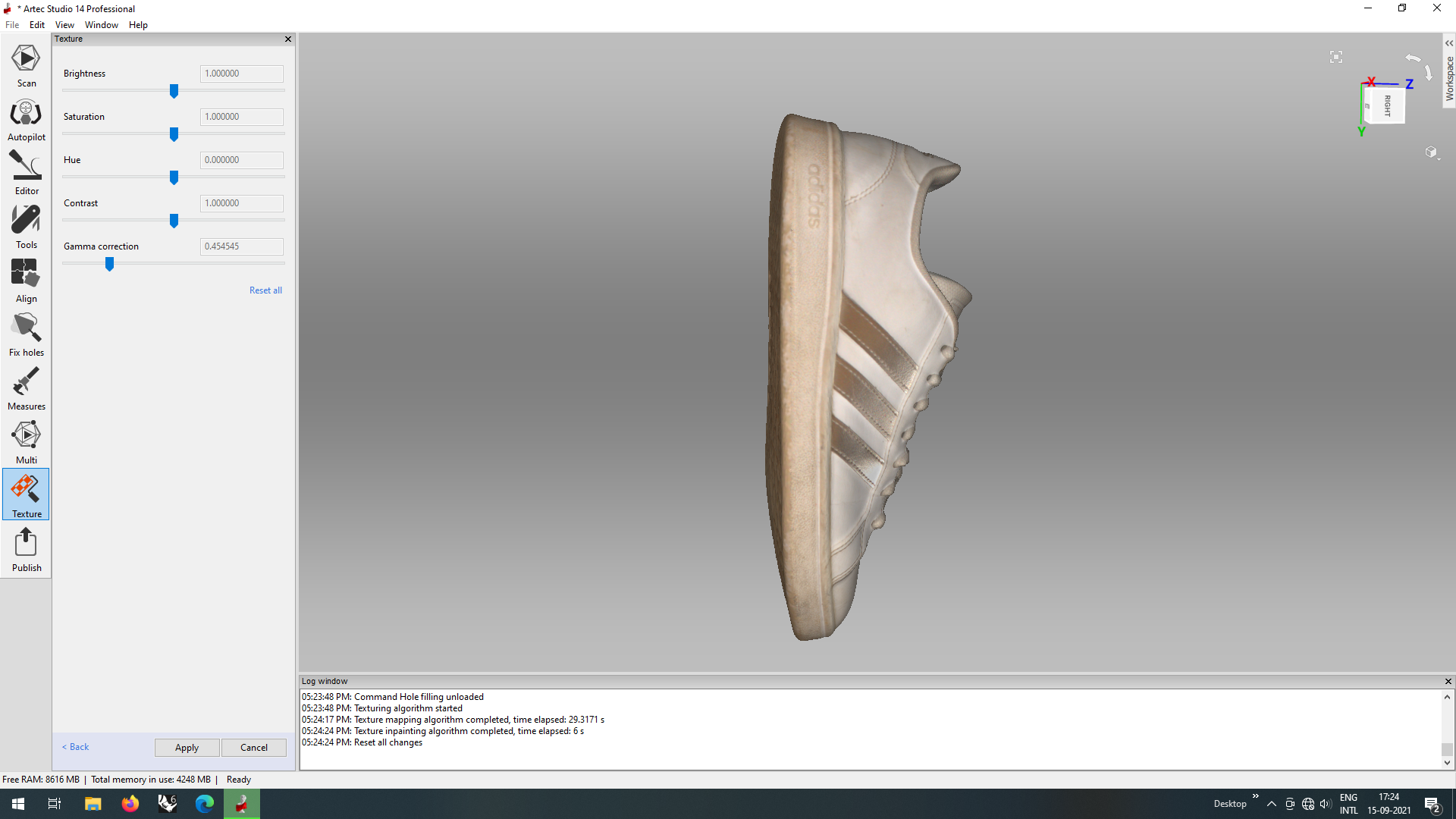
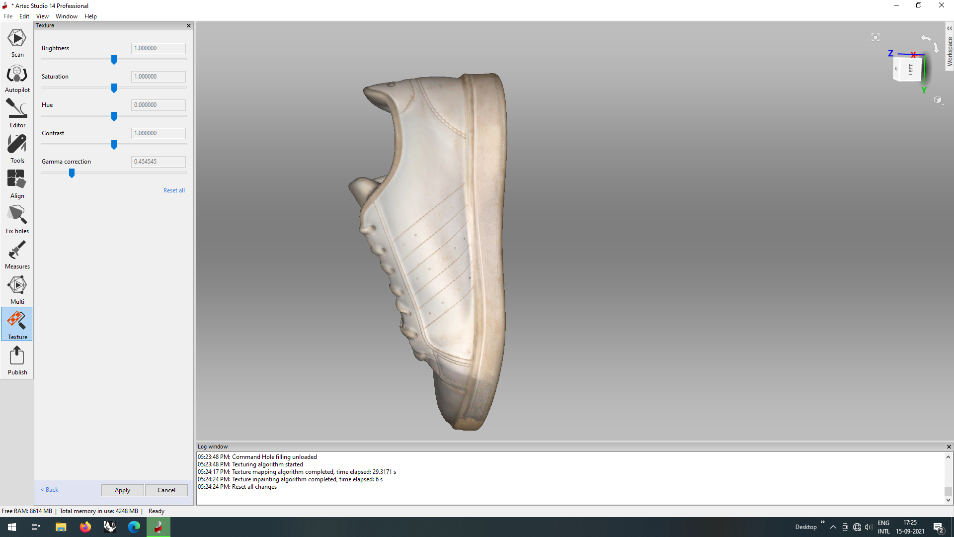
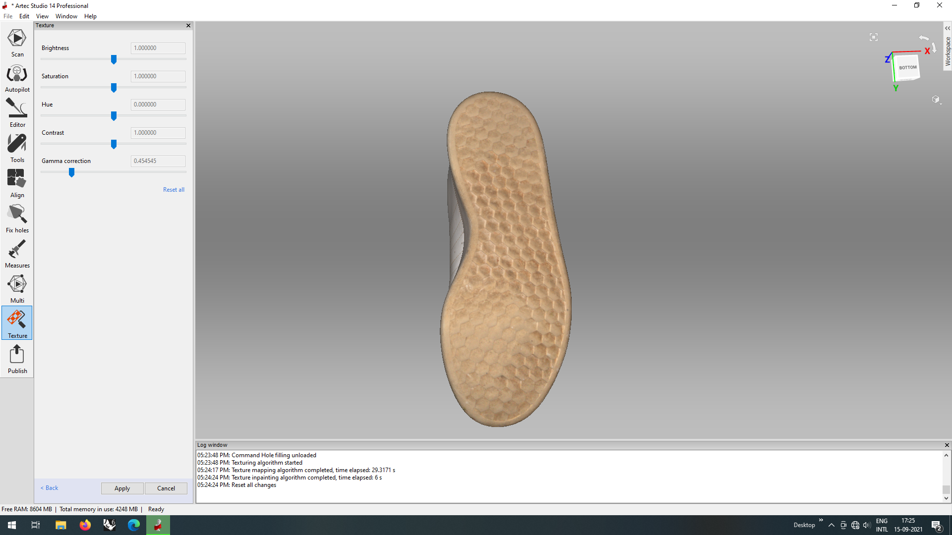
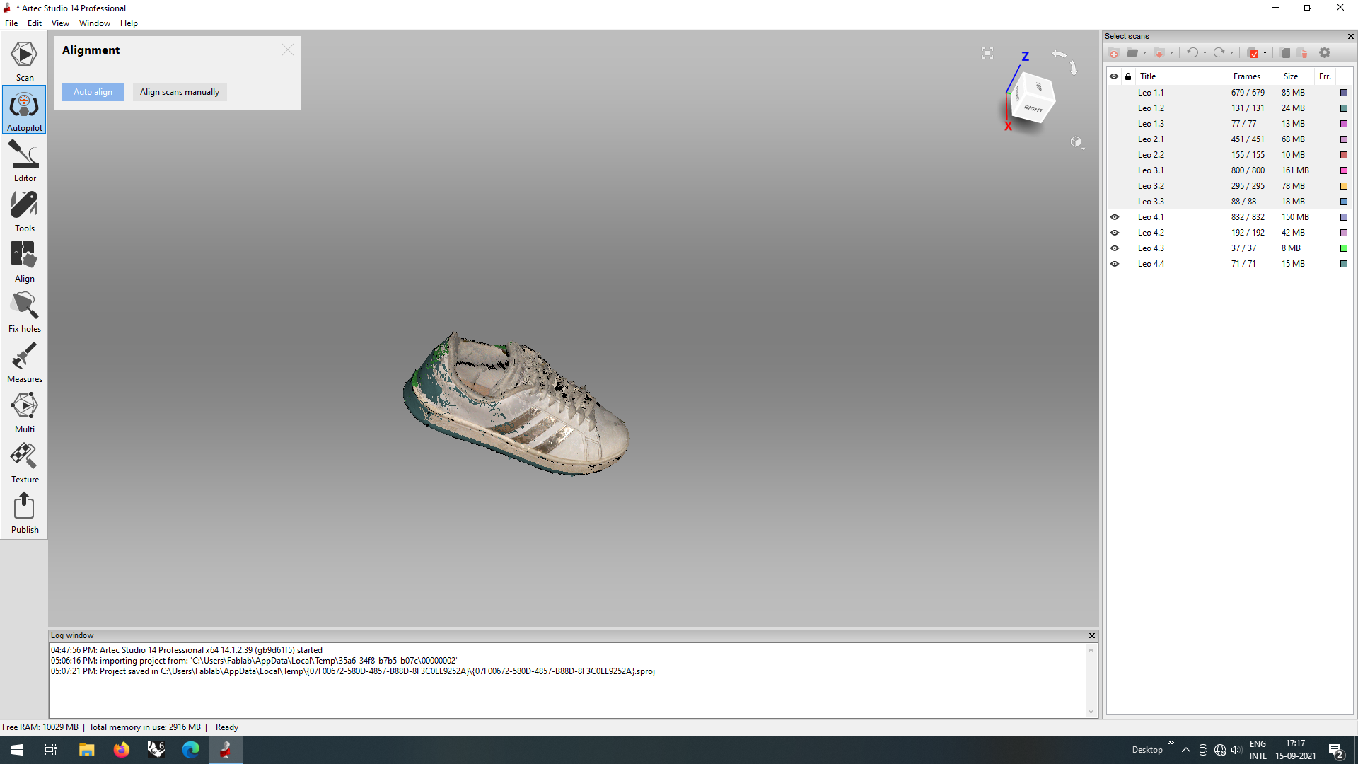
Once the edits were done, it was visible how the scanner even captured the texture of the shoe and the colors so perfectly. The final scan and the shoe can be compared with this picture.
Files
The .ply files of the shoe can be found here
The .obj file for the show can be downloaded from here