Week 3
Computer Controlled Cutting
This week, was Computer Controlled Cutting where we got to learn, understand as well as work with multiple machines. I learned how to use a computer to control the working of these machines and how to control various parameters in these machines using a computer- Including speed, intensity, kerf, cutting force etc. I also learned about what types of designs are compatible for what machines and how mods are used and how it works.
This week's Group project is to characterize our laser cutter, making test part(s) that vary cutting settings and dimensions and to define the kerf of the laser. The Individual Assignment is to design and cut something on the Vinyl Cutter as well as the laser cutter as steps to understand thr working of these machines.
Tools Used
Mac OS BigSur Ver. 11.1
Windows 7
Adobe Illustrator
FabMods
Vinyl Cutter
Terminal
Challenge: Understanding mods was a bit difficult at first especially when I had to start it using terminal, but then I got used to it.
Understanding and Working with Mods
Mods is software tool developed by MIT's Center for Bits and Atoms (CBA) to help build digital fabrication workflows in a modular way. It takes a design in one format, process through its algorithm consisting different modules calculating and analyzing the file and finally generate code that machine can understand and send it to the machine. Best part of it is that we can visualize all the process and know about the flow of the process. And secondly, it can be used for operating multiple digital fabrication devices like vinyl cutter, laser cutter and CNC mills in Fablab.
How to setup the Mods
-First, you need to install Mods using
Git Bash-Next, you need to type inside the mods file directory to start it
bash start-servers-Now, you need to select Roland GX-24 and need to upload the PNG file -Further, you need to run the calculation and need to setup velocity and force (40 cm/s & 110gf) -Since the parameters are change now you need to close and open the socket -Finally, you need to run the code by clicking button called
Send File to Device
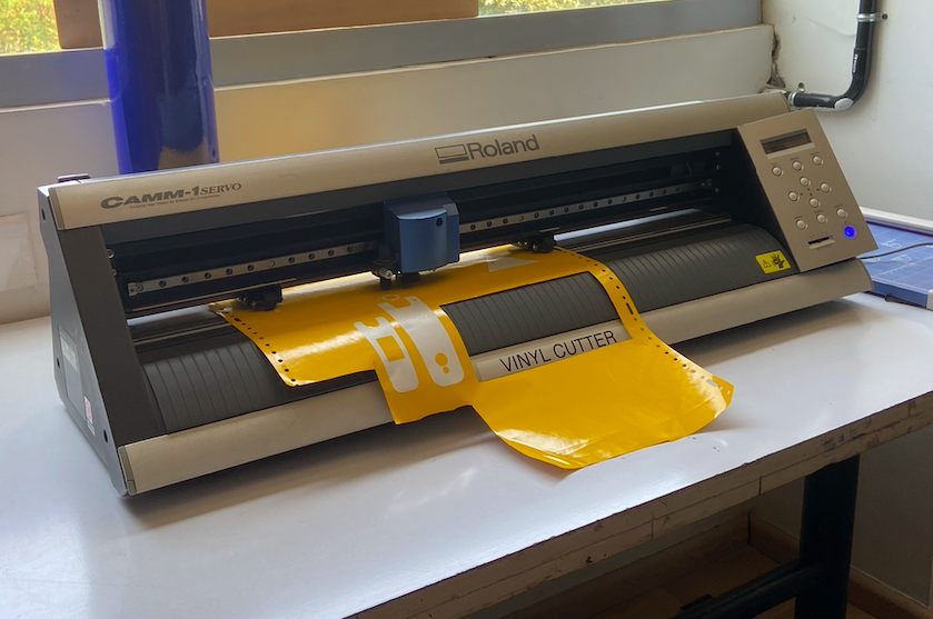
Vinyl Cutter
This computer controlled machine can be used to cut out letters, designs, and shapes on vinyl by moving a sharp blade against a thin vinyl sheet. It can also be used to make circuits out of copper sheets, cut paper, etc. We use the Roland GX 24.We also tested the fore and speed of the machine.(Apparently, it is super-important)
How to setup the Vinyl Cutter
-First, the Pinch roller is released and the material is loaded manually through the Grit Roller
-Next, it is ensured that the grit rollers are right above the markings and the pinch roller is locked into position
-With the help of navigation buttons in operation panel, the material is moved to required location
-The machine then automatically takes the width of the material and diplays it in the screen
-Now the origin is set using the button and a trail cut is conducted to check the velocity and force
-Once the cutting is over, the material is then removed using a knife swept through the knife guide
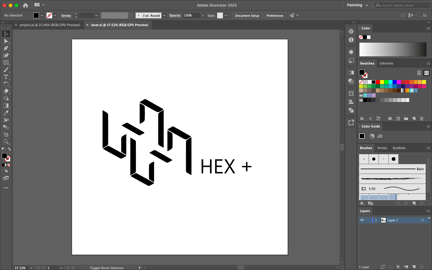
Designing and Uploading design for Vinyl Cutter
Vinyl cutters can take inputs in the form of vector, .png and .pdf files as the mods will process it. I designed a logo on Adobe Illustrator in black and white contrast. The design was done from scratch and designed with the shape of hexagon in mind.
The design was converted to png format and loaded to a usb. I then used Mods to upload my design file to the machine.
For this, I opened Mods on the computer using terminal and selected my file from the USB that was connected.
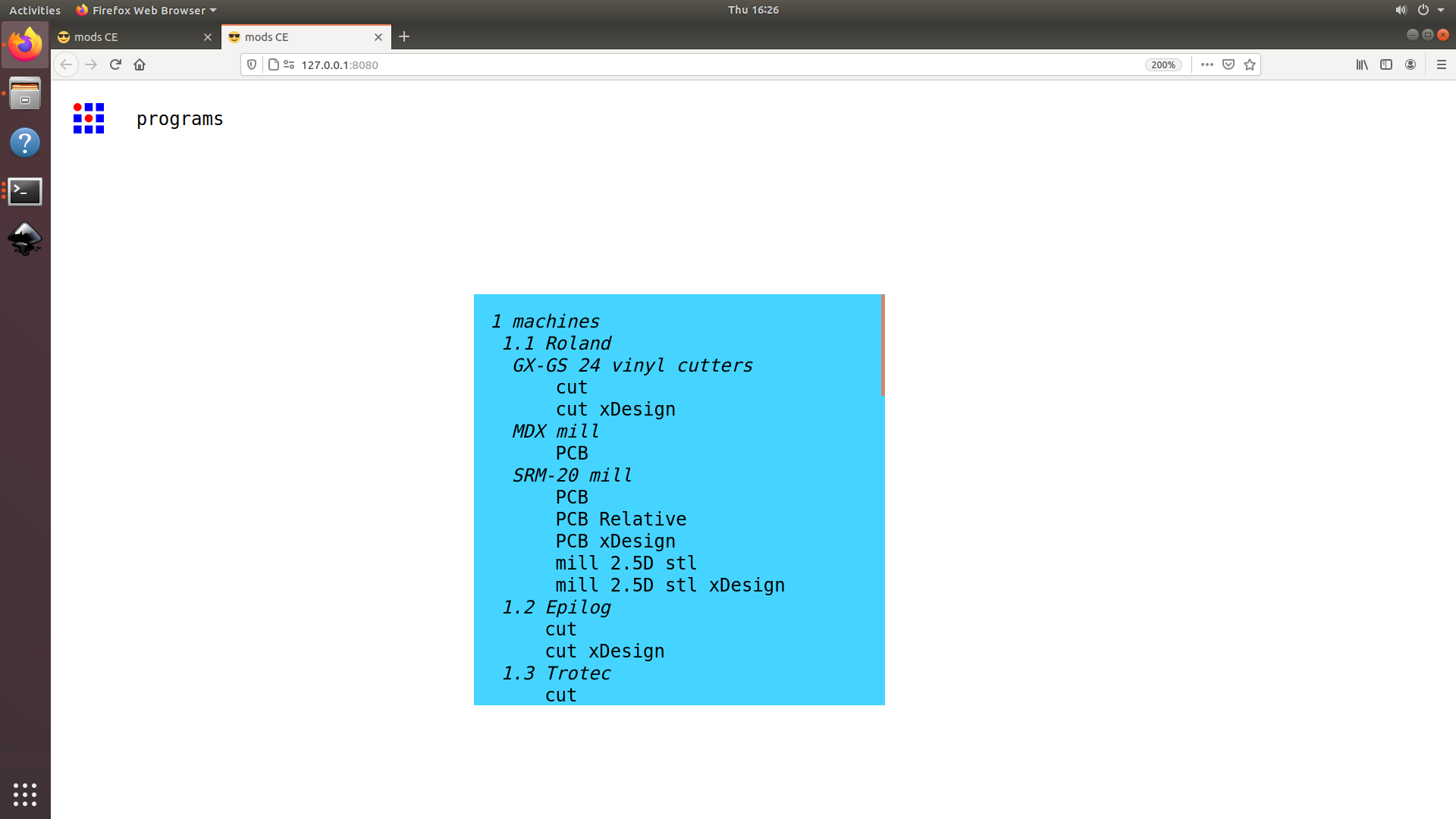
At this point, you can either enter a svg file or a png file as an imput. I selected the png file. Enter the tool diamater and hit calculate. As soon as you hit calculate you can see all the process in the flow and final tool path can be seen.
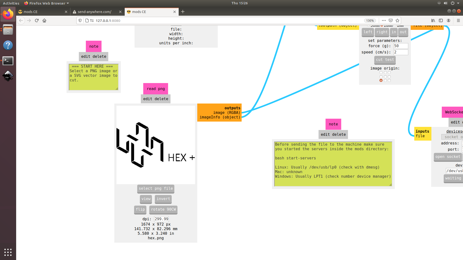
Next, check whether the tool path is ok or not. Some times, if the image is too small or if there is any image procesing problem, if tool path may not be as per our expectation so please make sure it is ok before starting the cut. Then select the cutting speed and the cutting force for the machine. Open the web socket and click on the "send file to device" which should start the cut.
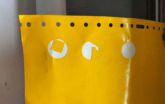
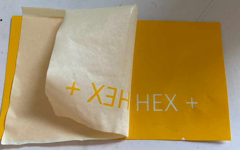
Cutting and Weeding
Once the input was given, the machine started to cut the pattern. Once the cutting was done, I pasted a masking tape on the vinyl and then pressured the regions that i needed. On removing the masking tape carefully, I got the portion I needed, stuck on to the masking tape.
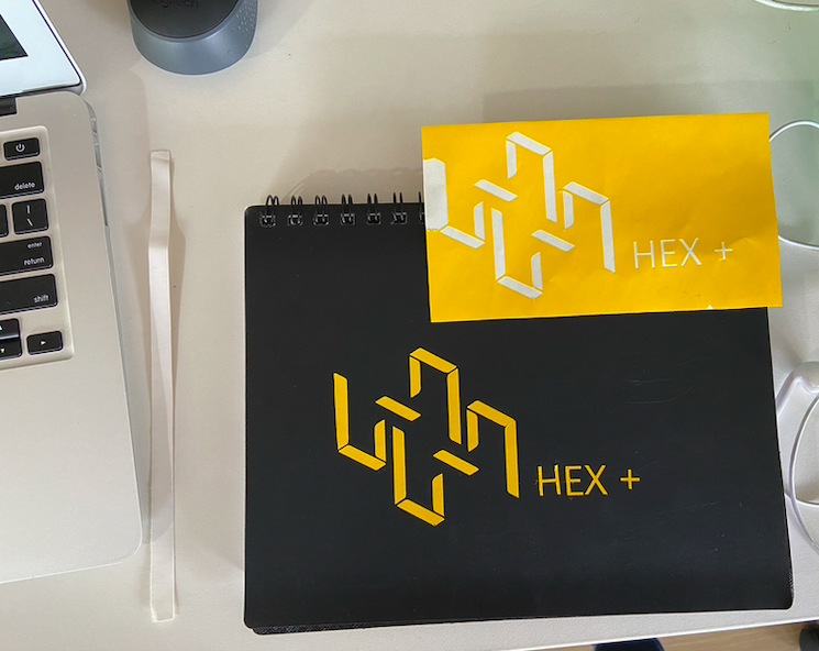
Final Results
The final result of the vinyl was a logo sticker that I stickered to my notebook.
Understanding Parametric Design
Parametric design is a process based on algorithmic thinking that enables the expression of parameters and rules that, together, define, encode and clarify the relationship between design intent and design response. Visit this page and watch the video to understand Parametric design better.
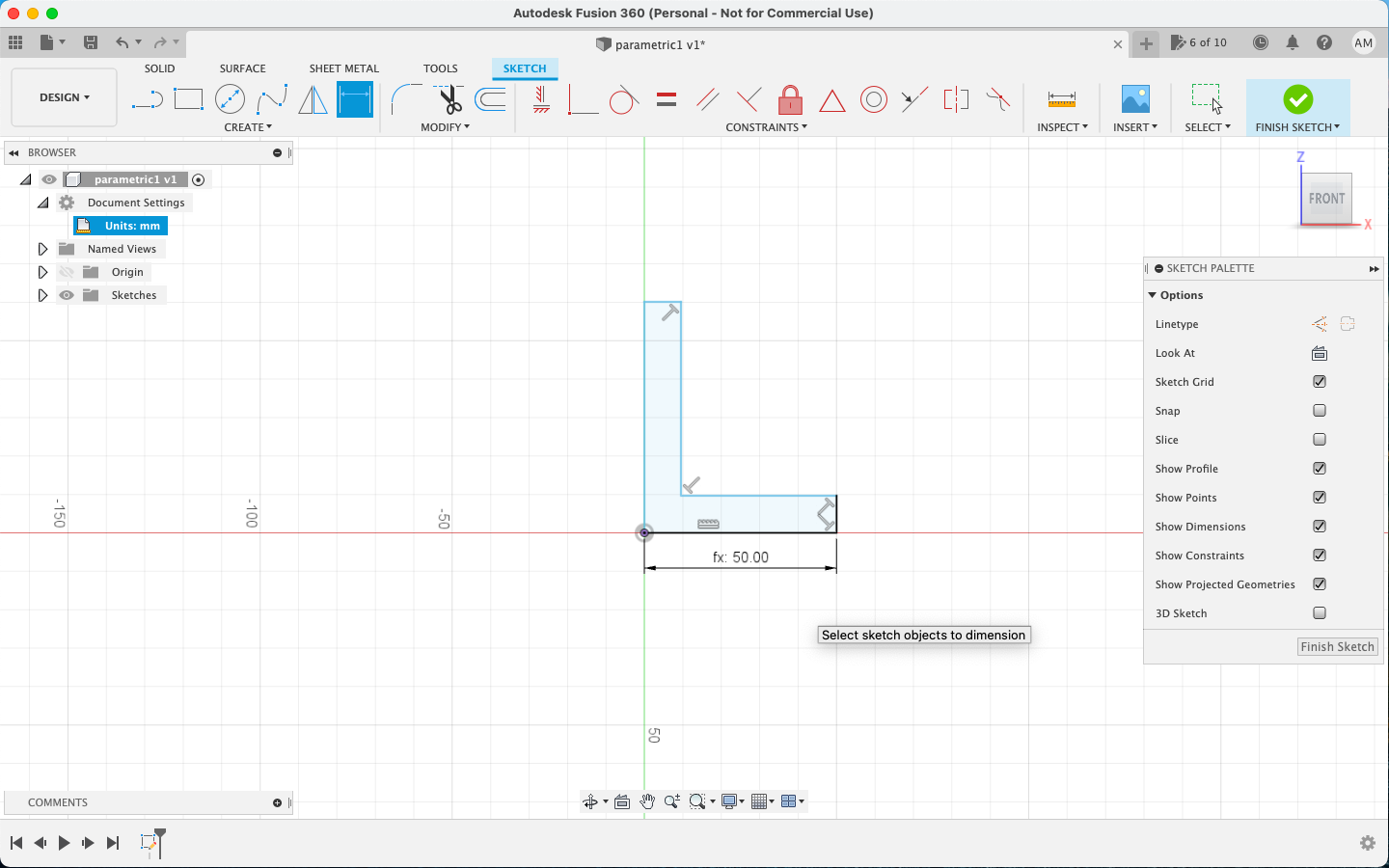
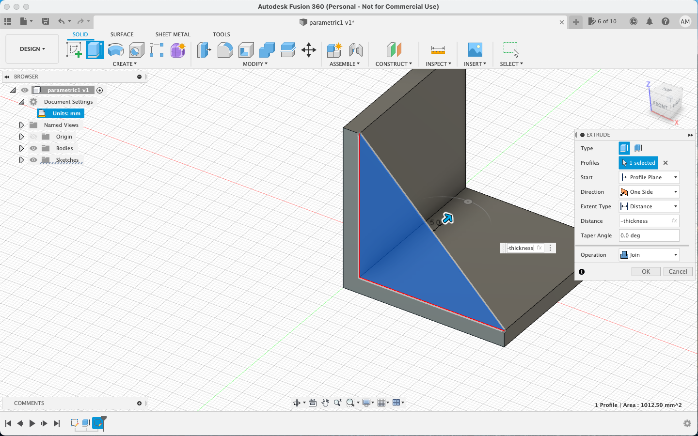
Since I am not proficient with Fusion and I wanted to explore parametrics, I decided to start with something simple. So I designed a simple L racket to start of and tried applying parametrics t understand better.
Laser Cutting
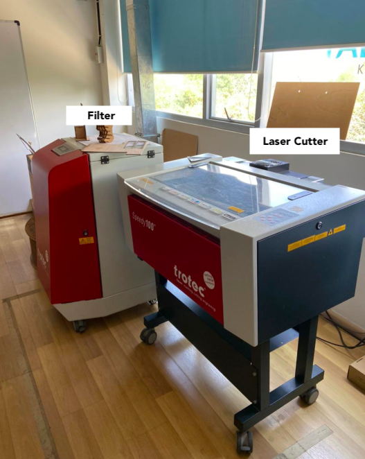
My experience with Laser machine was rather remarkable. I made some mistakes and even got my cardboard burnt. I tried different inputs and checked the outputs. In our lab, we use the Trotec Speedy 100.
Individual Assignment
This week's Individual assignment was to design and cut something in the laser cutter applying parametrics. We were also supposed to make a parametric construction kit.
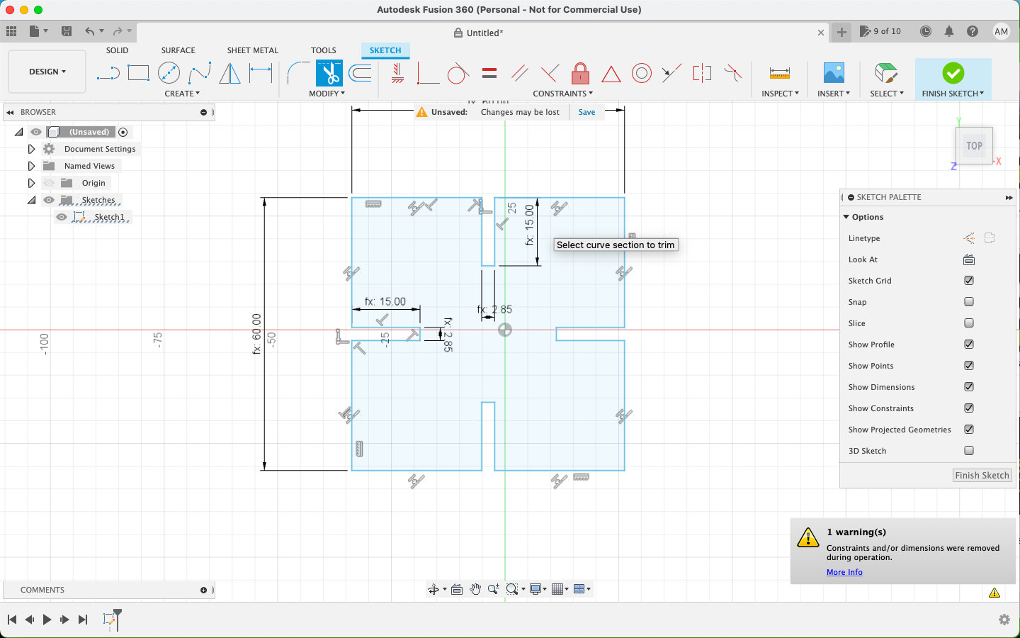
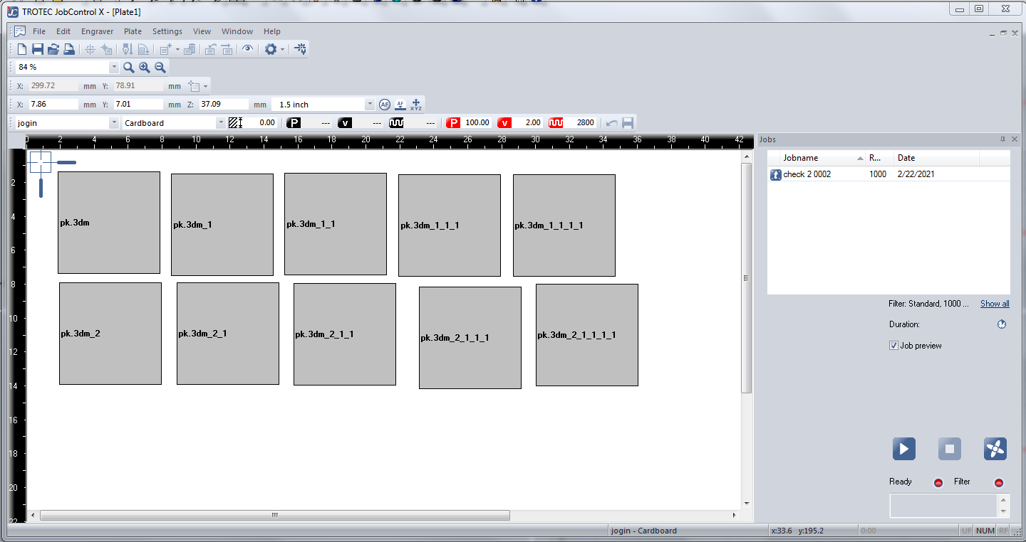
I designed a basic shape allowing press fit on four sides. I designed it in Fusion 360 and then copied multiple jobs before cutting. I initially set uo the value as 1.5 and it didnt cut through. So I decreased the value to 0.5 and the cardboard caught fire. The rest of the pieces were cut with 0.8. I found out the problem to be with the cardboard piece. It was slightly bent.
The original file of the same can be downloaded from here
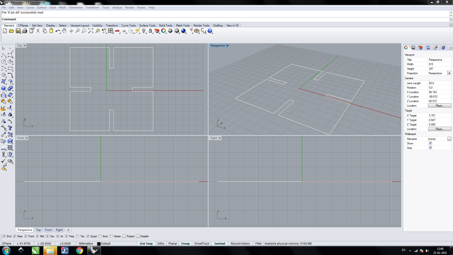
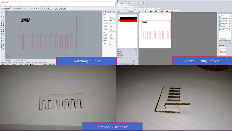
Once the 3D design was done, I converted it to a dxf file and imported it to Rhino, where I checked the final print lay and set the color of borders to cut.
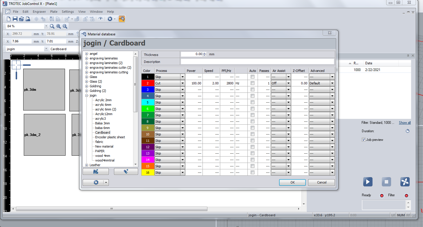
After this, I opened it in the Trotec software to set the jobs and also to set the parameters of the cut.
The first few cuts failed miserably but I did learn a lot on how to work with a laser. I did the same design again on a different less bent piece of cardboard and gave the right inputs.
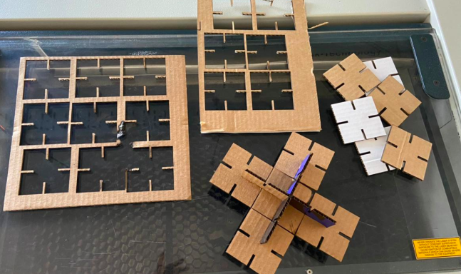
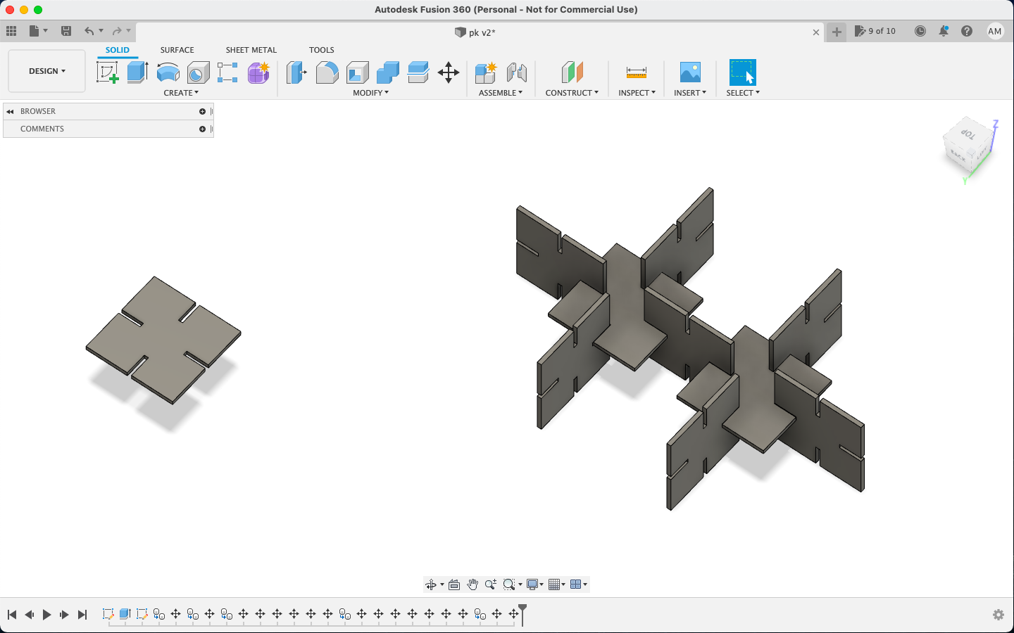
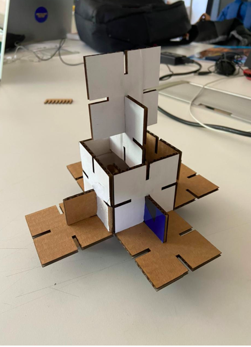
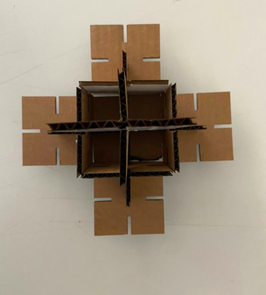
Once the pieces were cut, I built a small satellite kind model out of it!
Group Assignment
This week's group assignment was to characterize our laser cutter's focus, power, speed, rate, kerf, joint clearance and types.
For this, we were first introduced to the laser cutter and the way it is operated. We were also introduced to multiple keyword related to laser cutters.
The laser burns away a portion of material when it cuts through. This is known as the laser kerf and ranges from 0.08mm – 1mm depending on the material type and other conditional factors. Although above c0.45mm is only experienced when cutting thicker foams. Any areas in our design where cut lines come closer than 0.5mm together could burn away entirely. Any details narrower than 1mm are likely to be very fragile and in some cases can cause the material to warp whilst cutting. As a benchmark, the recommended minimum cut widths be no smaller than the corresponding thickness of the material. For example, if cutting from 3mm acrylic, it’s best not to allow any widths less than 3mm. We can go smaller but this can make your pieces very fragile which might not be suitable for our application. Kerf is determined by material properties and thickness. But other factors also have an impact on how much the laser takes away. The focal length of the lens, pressure of compressed air both have an impact. Kerf widths can vary even on the same material sheet, whether cutting a straight line or a curve line or from laser cutting in the x or Y dimension. The manufacturing tolerance of the material can also impact the kerf.
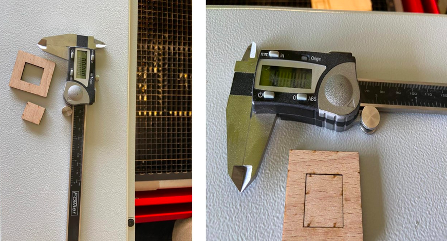
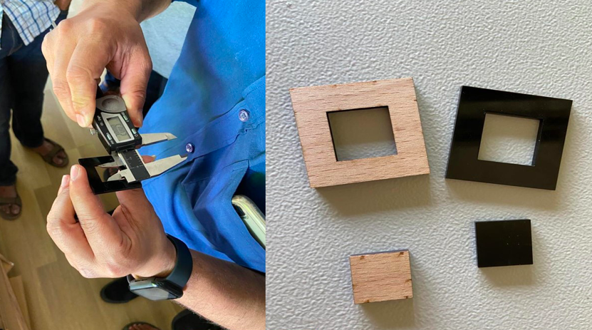
The kerf of wood is : 0.15mm
The kerf of arcylic is : 0.2mm
Files
The dxf file for the vinyl cut can be downloaded from here
The dxf file for the laser cut can be downloaded from here