9. Machine and mechanical design
Group assignment
- Design a machine that includes mechanism + actuation + automation
- Build the mechanical parts and operate it manually
- Document the group project and your individual contribution
Group machine idea
Teddy Warner, Graham Smith, Grant Fleischer, and I decided to make a pizza maker CNC machine. The idea is that we have a normal CNC machine with an X-axis, Y-axis, and Z-axis as the bare skeleton. We also incorporate tool changing to switch between a hopper dedicated to dispensing pizza sauce and a second hopper dedicated to dispensing cheese.
My job
My job for this group machine was to design the hoppers that would hold the sauce and cheese, the hopper mounts, and make a GCODE script that the machine could read.
Hoppers
There were several things I had to keep in mind when designing the hoppers:
- I have to design it so that it fits together with the hopper holder on the gantry that Teddy Warner
- Adjust the hole diameters for different consistencies (sauce vs. cheese)
Servo arms
When designing the servo arms that are going to be used to open and close the hoppers, I actually used slightly different servos. The reason is that we already had one type of servo in the lab and it already had a sort of “stand” with bolts where I could screw something in. This “stand” had 4 spaces for bolts which is why the end of the sauce servo arm has 4 holes. I did this because I could easily talk measurements and prototype before the other parts came in that we ordered. In hindsight, this is not a very good idea since it would obviously have been a lot easier if everything was based off of the same dimensions and the same standard.
This is the servo arm that is used for the sauce hopper.
This is the servo arm that is used for the cheese hopper.
Hopper holders
GCODE
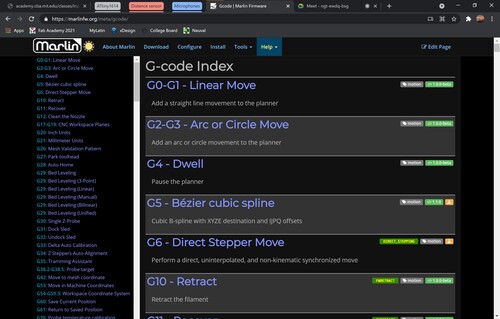
I did not know anything about GCODE other than the fact that it is a format that machines can understand and that each command correlates to a specific movement or change. I used this website extensively while figuring out what commands to use for what task. This site offers brief explanations of hundreds of different commands.
Servos
The first thing I needed GCODE for was just to have an understanding of what each servo position meant. Using the website mentioned above, I first decided to find the command that is meant for servo angle positioning. After doing a routine “ctrl + f” command to find anytime on the page that the word “servo” is mentioned, I found this page
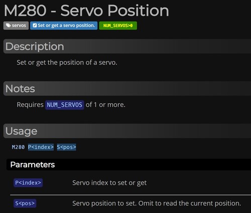
This page offered an explanation of how to write commands to change the servo position. Teddy had configured the Mini RAMBo that we used to turn motor pins to become servo pins. When we attached the servos from each hopper to different servo pins, we were able to identify how each servo would be addressed in the GCODE. We found that the cheese servo had to be addressed as “P0” and the sauce servo had to be addressed as “P1”.
This meant that we already had 2 of the 3 parts to make this command complete. The last part was to change the angle of the servo. I had to experiment quite a bit to find out which angles we would actually need to use. To adjust the servo to that angle position I just have to type “S” + desired angle.
These are the important cheese servo angles:
M280 P0 S8 // cheese servo closed
M280 P0 S15 // cheese servo half open
M280 P0 S21 // cheese servo completely open
M280 P0 S27 // cheese servo half open (other side)
M280 P0 S36 // cheese servo closed (other side)
These are the important sauce servo angles:
M280 P1 S30 // sauce servo closed
M280 P1 S38 // sauce servo half open
M280 P1 S43 // sauce servo completely open
M280 P1 S48 // sauce servo half open (other side)
M280 P1 S55 // sauce servo closed (other side)
Tool changing
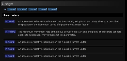
The tool changing aspect was not difficult, but did take a lot of time and effort. Since all of these movements would occur in a straight line (as opposed to an arc or a circle) I had to use the “G01” command. This page talks more in-depth about the aspects of this command. This command is actually quiet simple though since the only things you have to write is “G01” and then the desired XYZ coordinates. For example, to move the gantry to “143, 67, 17” the command would be “G01 X143 Y67 Z17”
This is the tool changing code to pick up the sauce hopper:
G28 // home the machine
G01 X86 Y14 Z5 // start pos for tomato hopper
G01 X148 Y14 Z5 // get z-axis right above holder
G01 X148 Y14 Z14 // lift to get the hopper on the z-axis instead of holder
G01 X100 Y14 Z14 // pull out with the hopper
This is the tool changing code to pick up the cheese hopper. As you can see, the only difference between this code and one for the sauce hopper is just the y-coordinate. Instead of having “Y14” as the coordinates, I just had to change it to “Y250”
G28 // home the machine
G01 X86 Y250 Z5 // start pos for cheese hopper
G01 X148 Y250 Z5 // get z-axis right above holder
G01 X148 Y250 Z14 // lift to get the hopper on the z-axis instead of holder
G01 X100 Y250 Z14 // pull out with the hopper