7. Computer controlled machining
Individual assignment
- Make (design + mill + assemble) something BIG
Designing in Fusion360
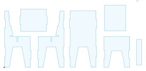
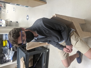
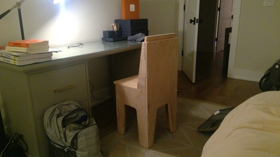
For this week’s project, I decided to make a chair. The chair I have in my room currently is rolly and the wheels make a very annoying amount of noise. Anytime I work at night, my parents can hear me move my chair since their bedroom is directly below my room. My instructors suggested that we attempt to make something that is snap-fit to avoid having to use any sort of screws, nails, or adhesives. There were only a couple of issues that I encountered when designing. The first is that the scale of the chair is not very suitable. I took measurements of the chairs we have in our lab, but these seem normal sized compared to the relatively low desks. I will talk about this later when I include photos of the final assembly. Another issue is that some of my panels were a bit too wide, so I had to remill some of these panels. I will also include images of this and my solution later in this page.
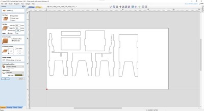
These are the images of my original design file in Fusion360. I designed them on the XY plane since that is that is the plane on which the design will be cut.
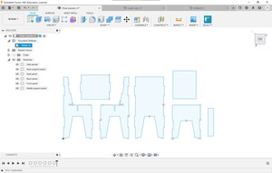
I also extruded each chair panel to the thickness of the wood and assembled these 3D panels to get a better idea of how the final product would look.
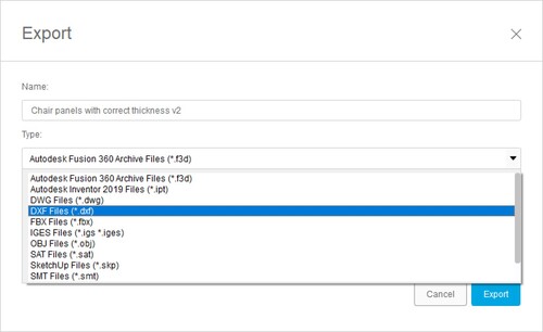
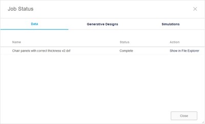
After having designed each panel, I had to export them as a “.dxf” for the next step.
CorelDraw
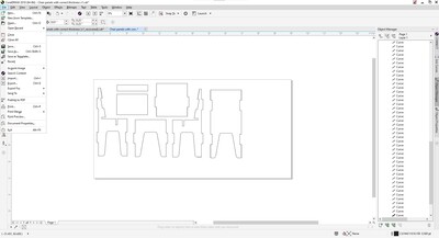
Now, I had to import that .dxf into CorelDraw and resize it.
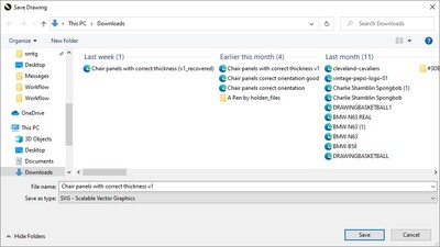
I am not sure why this happens, but sometimes the file completely changes scale, so certain edges that were supposed to be 15 inches ended up being more than 30 inches. All I had to do was just scale down the all of the shapes to the correct size. After all of this is done and all the panels are the correct size, I had to export this file as a “.svg”
Aspire
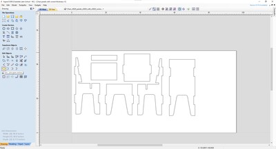
After I had my .svg of my chair panels, I had to open this file into Aspire.
The first thing that is necessary is ensuring that the size of the bed set correctly, including the length, width, and height.
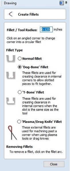
I am not sure why, but for some reason, each shape does not seem to be connected, meaning it is not possible to make dog bone joints. To resolve this, I had to select each panel individually and group them by joining each vector.
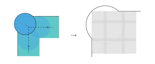
This is a dog bone, a type of joint that is common for tools like a CNC machine. In the image, the dashed line is the tool path of the bit and the dark blue circle is the bit itself. This article explains this concept more in-depth
This allowed me to make dog bone joints at each intersection to allow each panel to fit together snugly.
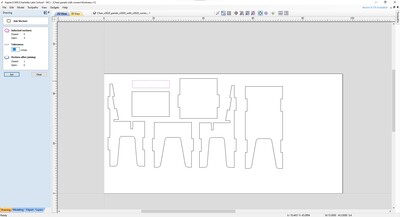
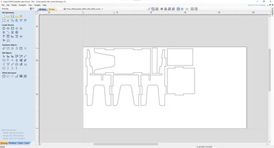
Another thing I had to do was rearrange all of my panels to conserve the most wood
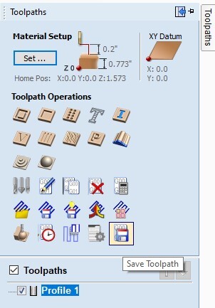
After all of that has been completed, I had to start making the tool path which is what the CNC follows to cut out the pieces. I started off by clicking “profile toolpath”
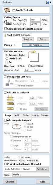
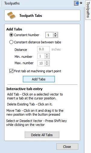
Next, I had to add tabs to ensure that the panels do not wiggle around before the entire cut is finished. I just activated the “add tabs” tool and placed one tab on each side of the panels.
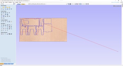
After all the tabs have been placed in the correct places, I clicked at the very bottom of the side bar where a button showed “calculate”. This means that the computer will calculate the tool path that corresponds with all the settings made above. That should render something like this:
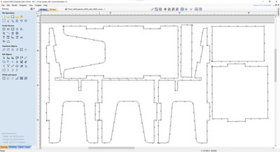
If I go back to the “2D view” I can see how the tool path compares to the panels. I also include an image of how the tool path moves in the joints to make the dog bone joints.
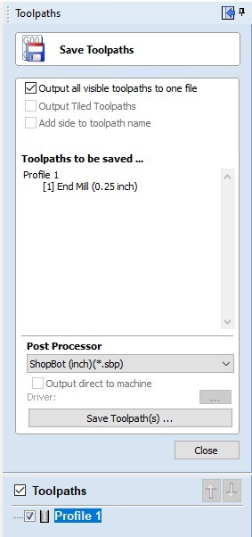
After ensuring that each joint is correct and everything seems right, you have to click “save toolpath” and save it as a “.sbp” file since that is what the ShopBot CNC recognizes
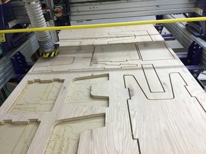
Cutting
This is the workflow for the ShopBot we have in the lab:
Mr. Dubick repeated that we should be able to show the workflow for the ShopBot within seconds of him asking. This is because it is an extremely powerful machine and each step is very well documented. He told us about student whose hair got stuck in the CNC bit and subsequently passed away. This was an important reminder that this machine is not to be messed around with and every single safety precaution must be taken to prevent injuries. The workflow can be viewed on this week’s group site linked below.
The only thing that I had to change on my design before actually cutting was the arrangement. One of my classmates had cut some of their pieces on the sheet of wood, so I just had to rearrange my pieces around that little area. To prepare the machine, I just had to follow the workflow that can be found in this week’s group site linked below.

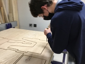
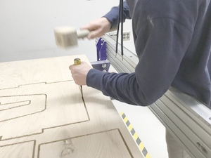
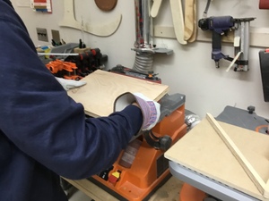
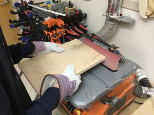
Removing pieces and sanding edges
Since I added tabs to the wood to keep it in place while milling, the first thing I had to do was remove those dabs. I did this by taking a chisel and placing it on a tab and then hitting the chisel with a mallet.

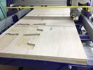
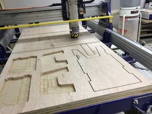
These are all of the pieces of the pieces that have been cut out.
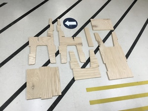
The next thing I had to do was sand the edges since the wood splintered in certain areas sine the cut was not perfectly clean.
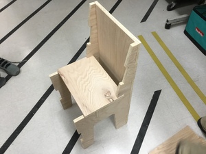
Assembling
All I had to do from here is just start assembling all of the pieces. This was actually very easy since each joint was tight.
The only issue (as mentioned earlier) is that some of the panels were not the correct size. I discovered that the reason was that for the back panel, I had a width of 15.00 inches and then I subtracted the area for the tabs, but this does not affect the total width, so it stayed at 15.00 inches. For the other panels where the tabs go out, I forgot to take into account that that would be increasing the total width of that piece. So instead of having a piece that was 15.00 inches including the tabs, it was ~16.50 inches. I addressed this issue by simply decreasing the size of the original rectangle (without the tabs) by the width of the tabs 2 times. This accounts for the tabs on each side. This meant that the original rectangle was ~13.50, but with the tabs, it came to the final width of 15.00 inches.
Resolving issues
The only issue (as mentioned earlier) is that some of the panels were not the correct size. I discovered that the reason was that for the back panel, I had a width of 15.00 inches and then I subtracted the area for the tabs, but this does not affect the total width, so it stayed at 15.00 inches. For the other panels where the tabs go out, I forgot to take into account that that would be increasing the total width of that piece. So instead of having a piece that was 15.00 inches including the tabs, it was ~16.50 inches. I addressed this issue by simply decreasing the size of the original rectangle (without the tabs) by the width of the tabs 2 times. This accounts for the tabs on each side. This meant that the original rectangle was ~13.50, but with the tabs, it came to the final width of 15.00 inches. I had this same issue on the front panel and the panel that supports your back when sitting. The final seat panel was just too short, so I just ahd to extend it by a couple of inches.
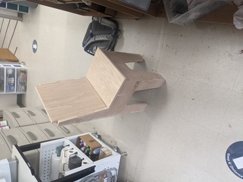
Final view
These are images of the final product.
Files
Group assignment
- Do your lab’s safety training
- Test runout, alignment, speeds, feeds, materials, and tool paths for your machine
For this week’s group assignment, I researched and wrote about the different types of runout and the possible causes of each. More details about this week’s group assignment can be seen at this link