3. Computer controlled cutting
Week 03 will be around computer controlled cutting. Here in Portugal we are currently in lockdown, so I’ll concentrate mostly on the designs and I’ll do the specific technical assignments of the machines later on.
Assignments
- Group assignment
- Characterize your lasercutter’s focus, power, speed, rate, kerf, and joint clearance document your work (individually or in group)
- Individual assignments
- Design, lasercut, and document a parametric press-fit construction kit, which can be assembled in multiple ways. Account for the lasercutter kerf.
- Cut something on the vinylcutter
I’ll start from the end.
3.1. Vinylcutter
The vinyl cutter is a CNC (Computer Numerical control) machine. The cutting head is comprised by a sharp blade controlled by a numerical device (e.g. computer, microcontroller).
Vinyl cutter machines can cut materials other than vinyl itself. Depending on the specs of the machine, it is possible to cut, for instance, cardboard, paper, stickers, stencils, fabrics, and other thin sheets of material, including conductive ones to make flexible circuits.
To cut a design one must use a vector image in one format the machine can interpret. In my case, I will use inkscape as my vector graphics program.
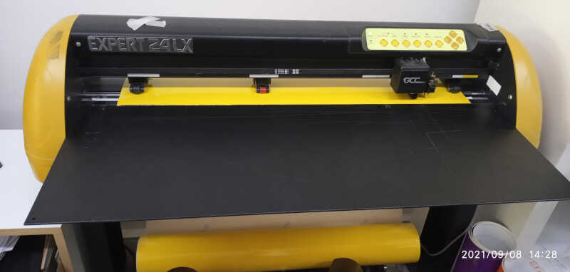
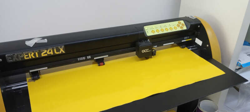
We will be using a local machine near my place. I will use the GCC Expert 24 LX, which is similar to this model and is shown in the picture below.
Pac-man scene
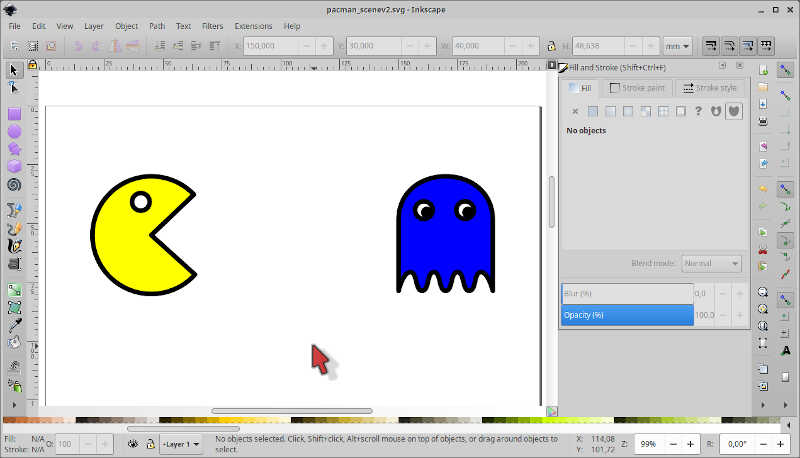
During week 02 I drew two pac-man characters: pac-man itself and a ghost. Now, I will create a scene on Inkscape based on this theme to cut on the vinyl cutter (and maybe on the laser too!)
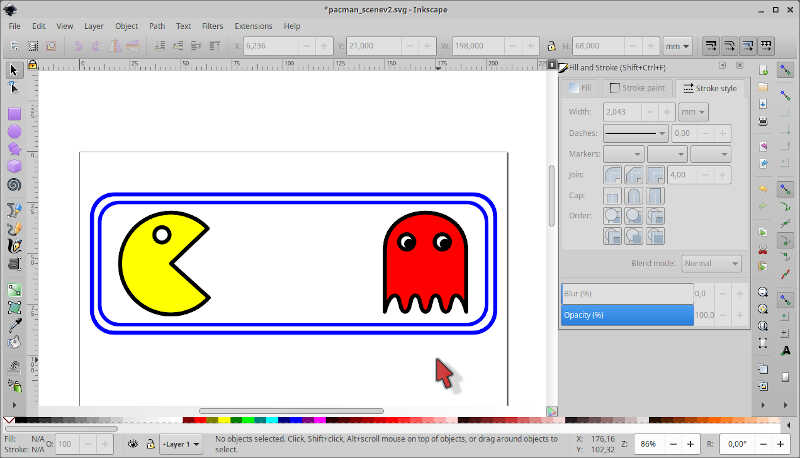
First, I will relocate the two characters to the extremes of the A4 framework. The pac-man will be on the left and the ghost on the right, 30 cm from the top edge, and 20 cm from the side edges.
Note: before starting, don’t forget to group the objects that are part of the two characters (CTRL+G)
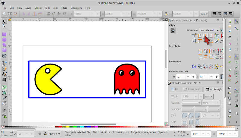
Then, I inserted a rectangle around them (width: 190, height: 60), removed the fill, changed the stroke paint to blue, with a stroke width of 2mm, and aligned it using Object/Align and Distribute - CTRL+SHIFT+a on the main menu and clicking on the icon of Center on Vertical Axis. To align horizontally, I selected the the option Relative to: Last Selected and the clicked on the box, then on the pac-man and clicked on the icon Center on Vertical Axis. I also change the color of the ghost to red for aesthetic reasons.
Note: Align and Distribute are really handy. It is worth exploring every option!
In the original pac-man, there are double, rounded walls. Here I’m going to do the same. To round the walls, I chose the Edit Paths by Nodes tool (Shortcut n), selected the square and clicked on the top right corner node. Then, I dragged it down to make the walls rounder.
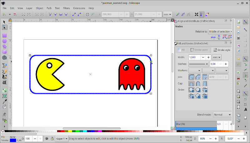
Ok, now I copied the wall and made another one (width: 198, height: 68), and aligned it with the first one.
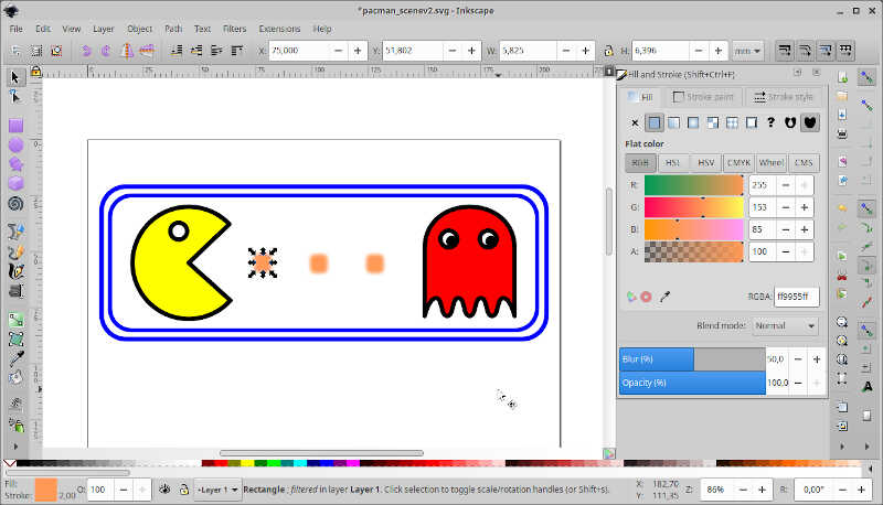
The next step is to do the pebbles. Pac-man needs to eat to finish the level so I added a few beige pebbles between him and the ghost, aligned them with the center of pac-man and place them at a distance of 25 mm between each other. I also added 50% Blur on them.
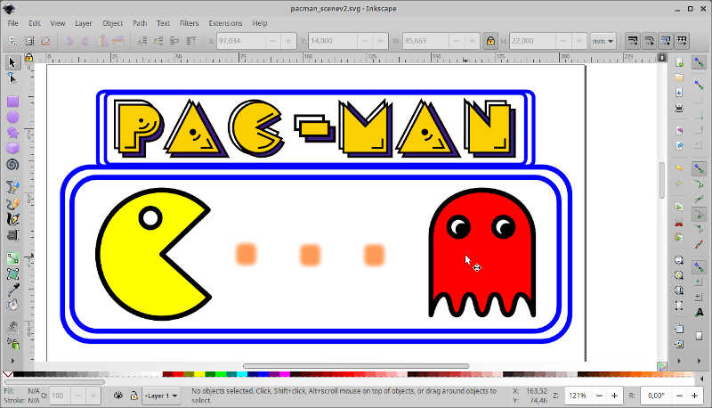
To finish it I wanted to add some fonts on the top of the drawing. However, regular fonts didn’t cut it, so I went after some real “pac-man” characters ;). I found these very nice ones created by RingoStarr39 on DeviantArt. I downloaded them from his google drive link and used them on the final design. I also added a new box around them.
To add the character images, I just dragged them to my sketch and included them as editable objects.
I also added a black background inside the boxes. To to this I had to add three layers (Layer/Layers - CTRL+SHIFT+l) and then move the inner boxes (upper and lower boxes) to the middle layer and the outer boxes to the bottom layer. From here, I just filled the boxes with black ink.
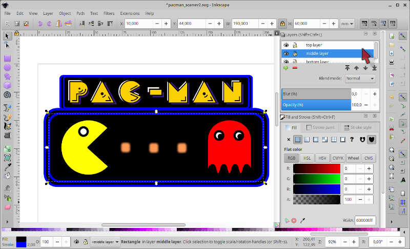
Ok, so this is version 0.1. Let’s see if I have time to improve on the design ;)
The v0.1 SVG file can be downloaded here.
NOTE: If you open it on inkscape it will open well. For some reason the pac-man is disappearing
Now I need to prepare the sketch file for the vinyl cutter. To do that, I needed to change the whole sketch. I disassembled the drawing groups and used repeatedly the Path/Stroke to Path tool so that I would keep only the outlines of the drawing.
For the art characters, I ungrouped them and chose the black part only. I also had to change the eyes of the ghost to a circle and a crescent moon. I did the crescent moon by intersecting and subtracting (Path/Difference) the two circles of similar diameters.
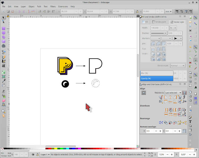
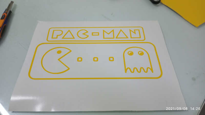
The end result looks like this, already resized for a landscape A4 fit. All paths have a width of 0.143 mm.
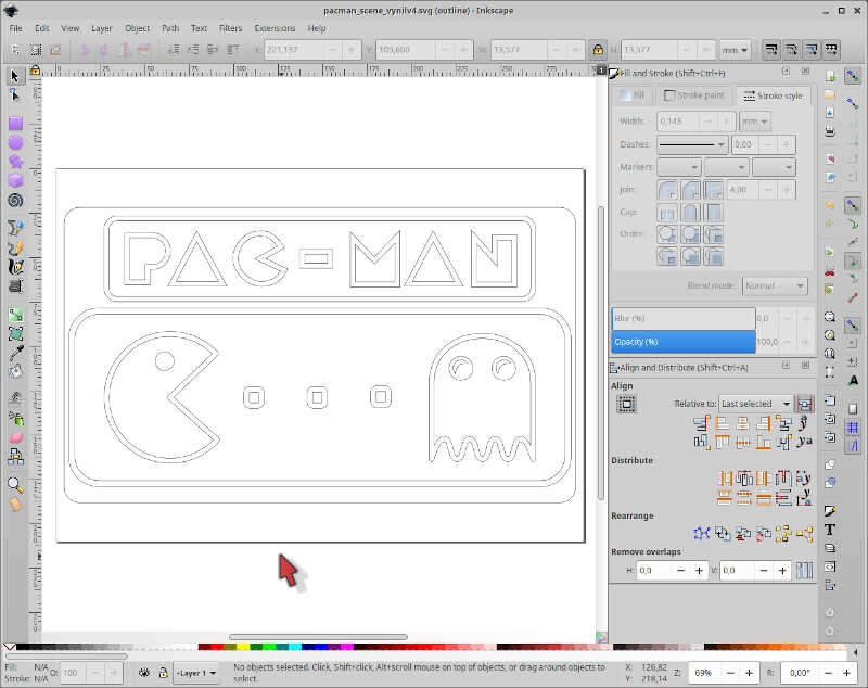
The SVG file can be downloaded here.
From here we went on to cut it.
Calibration of the vinyl cutter
To calibrate the machine, you need first to place the vinyl as shown in the previous picture and clamp it down with the three wheel guiders. The sensor on the machine’s head will detect the guiders and limit the width of the cut to that length.
Then, you turn the machine offline, by pressing the left most button. and place the vinyl at the starting line using the UP button, and finally clicking on the the ORIGIN SET button.
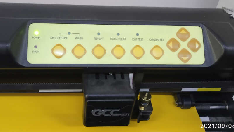
From here, you turn the machine online, again pressing the left most button. To calibrate the machine press the ORIGIN SET button three times. The machine’s sensor will find the left most wheel guider and set the maximum vinil width for the cut.
Cutting
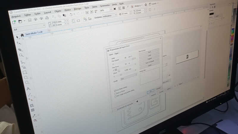
To cut the vinyl, a plugin of Corel Draw 2019 was used. Corel uses pdf file format, so the .svg was converted to .pdf prior to use.
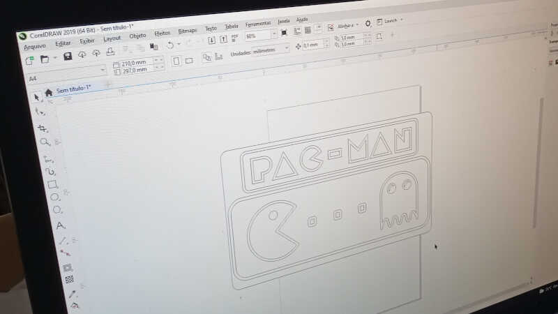
After adjusting the image, we set the printing properties of the Pen Speed to maximum, because the cut is simple, and the Pen Force to minimum because you don’t need more than that to cut this thin vinyl.
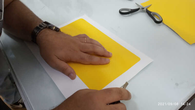
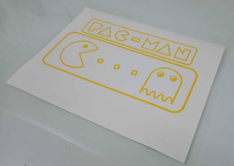
After printing, the result can be seen in the following picture. It looks like it didn’t cut anything but in reality all cuts are made!.
After removing the vinyl from the machine we started to take out with a cutter the material between what we want to keep.
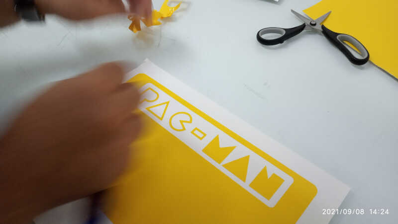
The final step is to attach a transparent transfer surface so that you can stick the vinyl drawing elsewhere.
That’s it!
3.2. Laser cutter
Laser cutting is the process CNC laser cutters use to slice or/and engrave materials. To cut materials, the machine work head directs the output of a powerful laser through optical components in order to focus the coherent light at the proper height and into a very small area, typically around ~ 0.025mm. The laser head is normally made by a nozzle, where air, a cutting gas or a controlled mixture of both is forced to flow at a certain rate to control the cutting and avoid ignition.
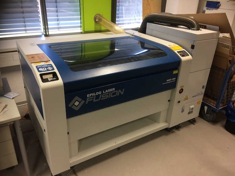
In the lab we’re going to use a 40 W CO2 laser machine, the Fabulaser. Unfortunately, the machine is not yet installed due to the lockdown and I used an Epilog Zing 24 from Fablab Kali (thanks Ferdi!).
Calibration and testing
As I’m working on a remote machine I’ll rely on the information given by the Fablab Kali 2020 group assignment.
Standard operation of the laser cut machine
- Open the lid and remove any large leftovers from the bed - if left unattended this can quickly go south (and the whole Fablab with it!)
- Place the material to be cut squarely against the upper left edge. Check it’s level in the bed. Use masking tape if necessary to tack it down.
- Turn on the laser cutter (switch below the emergency stop button).
- Select “focus” from the menu pad.
- Drive the bed down and away from the lens.
- Place the aluminum hanger on its studs. You need to do this to focus the laser.
- Drive the bed up until it just touches the hanger (watch for it to stop swinging).
- Centre the joystick and push it in to set the focal length. Remove the aluminum hanger.
- Select “jog” from the menu and turn on the spotter laser.
- Drive the head to the desired top-left position on the material.
- Push in the joystick to set the zero.
- Turn on the vacuum pump (button low down to the right).
- Set the menu to “job”. The machine is ready for computer input.
NOTE: NEVER EVER leave the laser cutter unattended!! The probability of a fire hazard is high!
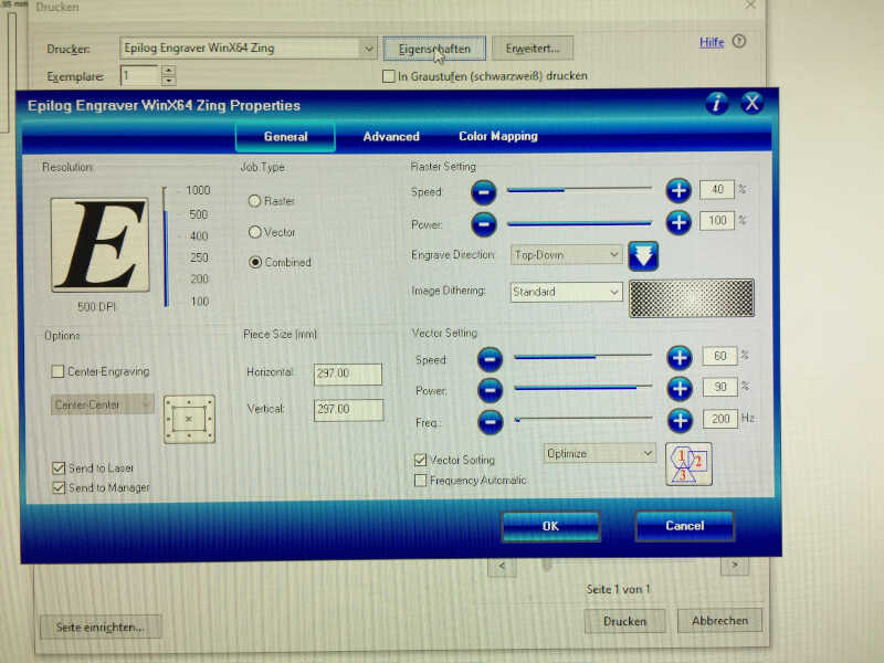
The epilog program allow us to change the properties of the laser cut, such as resolution, (from 100 to 1000 dpi), job type (engraving/cut), piece size, speed, power and and frequency of the engraving (raster) or cut settings, among others.
Determining the kerf and the engraving contrast
Kerf is simply the thickness of the material taken away when the laser cuts. The kerf changes with the material and its thickness. I will obtain a proper value according to the experimental calibration, type of material and its thickness.
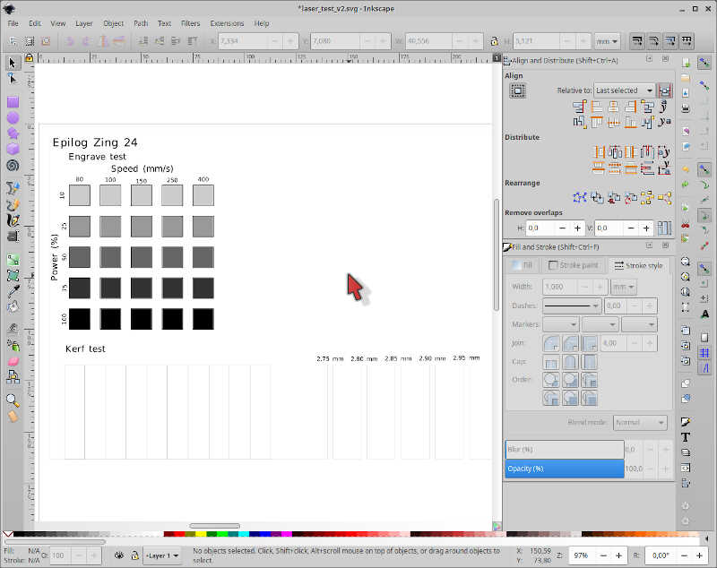
I made a standard engraving and calibration test sketch on inkscape, based on the information of the mentioned page:
- The kerf test will be evaluated in two ways:
- Calculating the length of what has been lost on ten 10mm long pieces (100mm in total).
- Evaluating the best fit for a 3mm thickness piece.
- The engrave test will show what happens when we apply different percentages of the laser power versus laser speed.
The SVG file can be downloaded here.
We will be using a 3mm MDF sheet. We took a look at the Epilog Laser cutter manual and first took the recommended speed/power combination for wood as shown on page 150, meaning 70s/100p @ 500 DPI for engraving and 70s/45p for cutting. We used a low frequency of 200 Hz to lower the risk of fire hazard.
We cut the kerf part first
And took away the parts from the MDF sheet.
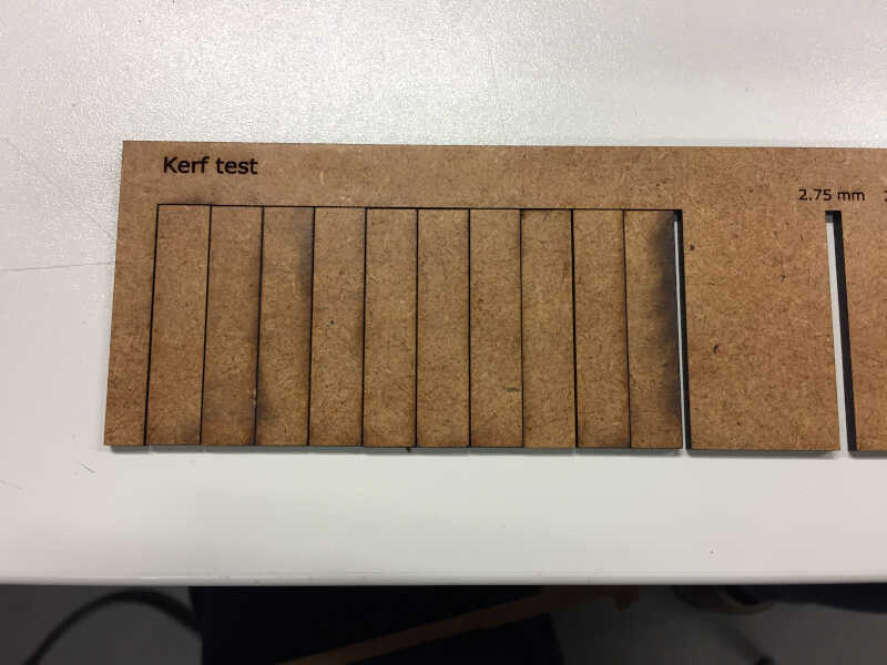
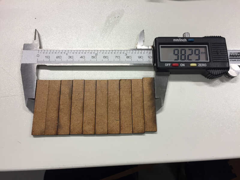
As we can observe, the length lost from the ten 10 mm cuts is
\(100-9.829 = 1.71 mm\).
This is the value of the kerf using this method.
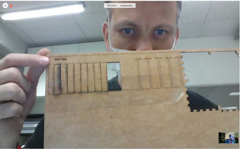
Next we tried to fit a previously cut 3mm thick piece into one of the calibration holes for thickness shown in the following picture.
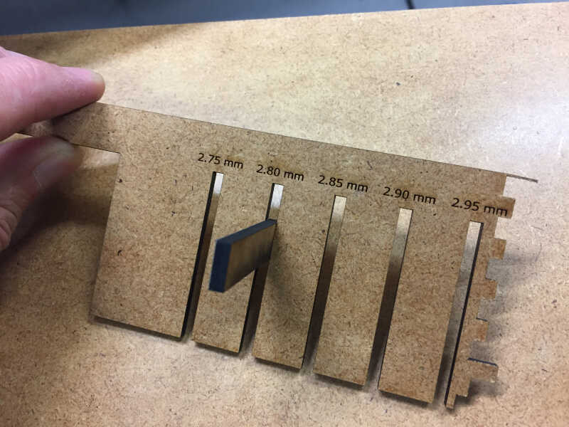
The best fit was observed @ 2.8mm, meaning that the right kerf should be
\(3-2.8 = 0.2 mm\).
The two numbers are consistent, so we should experiment now with a kerf of 0.2mm.
Following the kerf test, we prepared and cut the engraving test using a power versus speed matrix
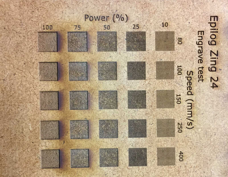
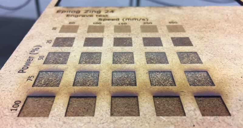
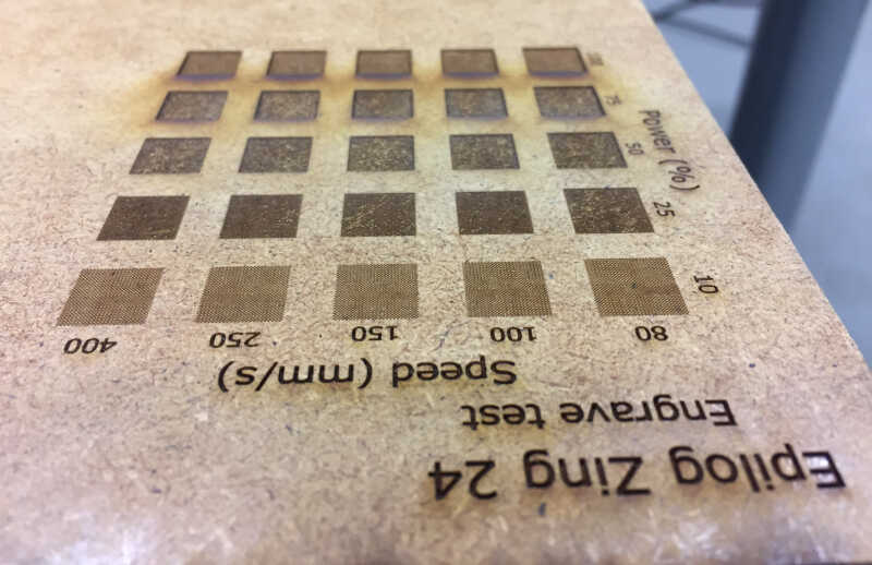
From the three pictures above we observe that:
- We can obtain basically three tones of “gray brown” by changing the power and speed of the laser.
- At 100% and 75% we observe a depth effect, not just surface engraving.
- Nothing seems to change with the laser speed, only with power.
Here we are going to use only one kind of engraving so we’re not worried about doing more complex patterns with techniques such as e.g. halftoning.
A very small poker die
I will do a very simple design at first. I decided to make a very small poker die for some random reason :) or maybe I just wanted to test the precision of the machine ;) The idea is to produce six small parts with a complex SVG engraving taken from an open picture repository from the internet. The sketches will be parametric so I can do a 1m die if I want to.
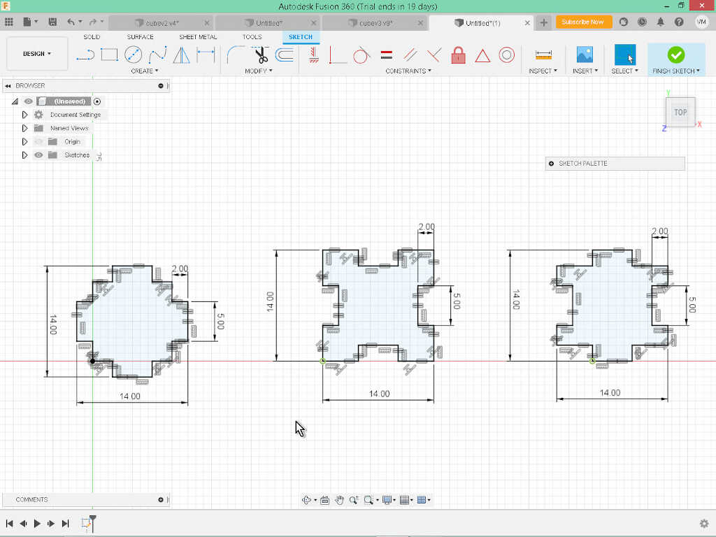
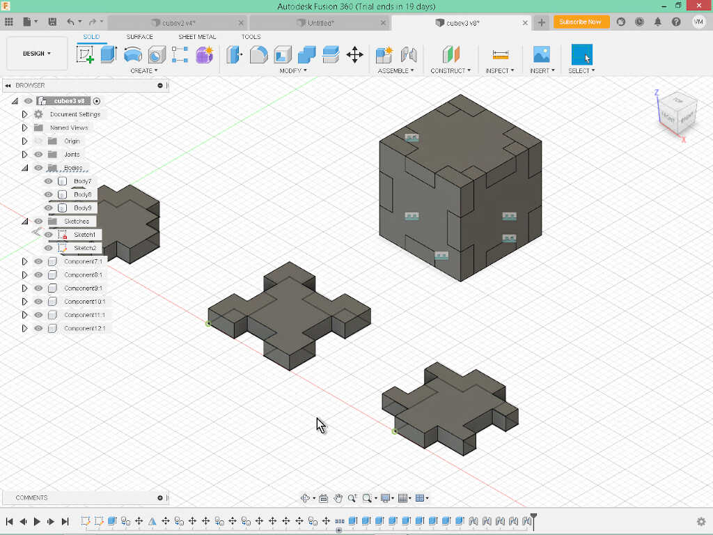
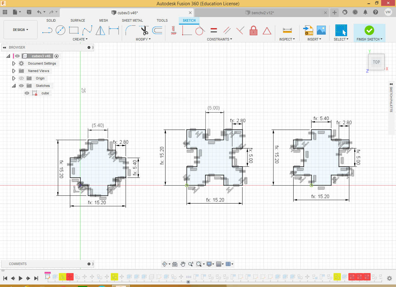
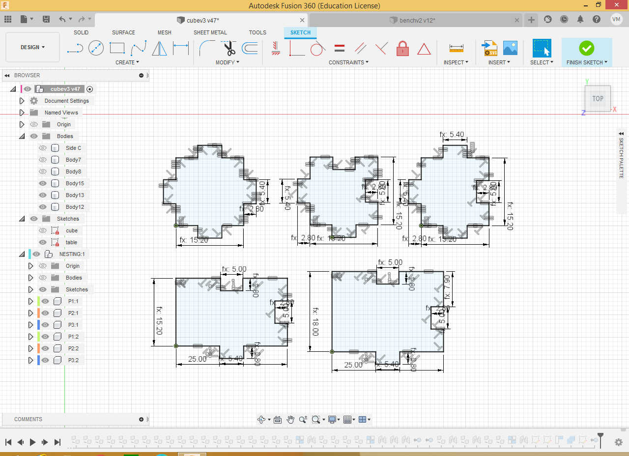
The first part involves doing the sketches for the parts. I’ve done this on Fusion 360. I wanted a cube with 14mm side length so after some trial and error I ended up with three constrained sketches:
- 1 sketch for the top and bottom parts (left)
- 1 sketch for the front and rear (center)
- 1 sketch for the left and right (right)
To do the sketches, I used a square first (11x11 or 15x15 mm) and then added rectangles to create the press fit joints. To finish them, I used the trim tool (Modify/Trim - shortcut t) on the sketches to cut away the sides in order to make simple pressfit joints. To close a constrained sketch I added some equality conditions to its walls.
From here I put in place some parameters (Modify/Change Parameters):
- Kerf = 0.2 mm.
- Press fit thickness = 2mm I need to take the kerf into account.
- Press fit length = 5mm
- Cube side = 14mm + 4*kerf. I want a 14mm side so I need to take into account the kerf.
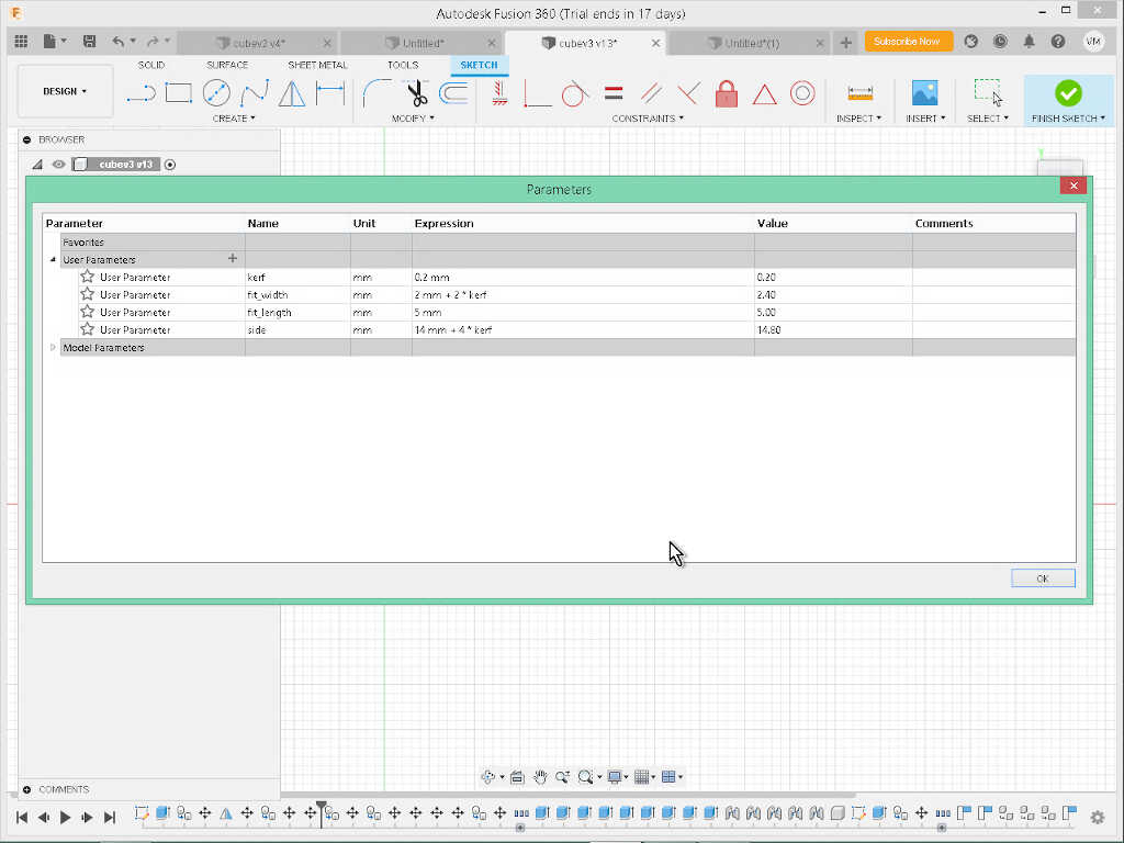
In order to make the press fit work, I experimented first with a 0.2 mm difference between the male and female joints. Now, the sketches are fully parametric and taking kerf into account.
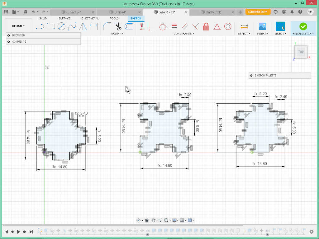
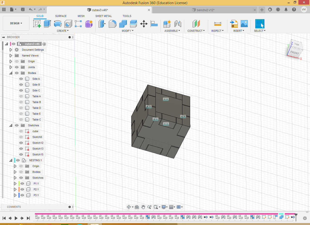
From here I created an illustrative 3d model of the die. First, I extruded the three bodies 2.4 mm high. Then I used the mirror and Move/Copy tools to multiply the three bodies.
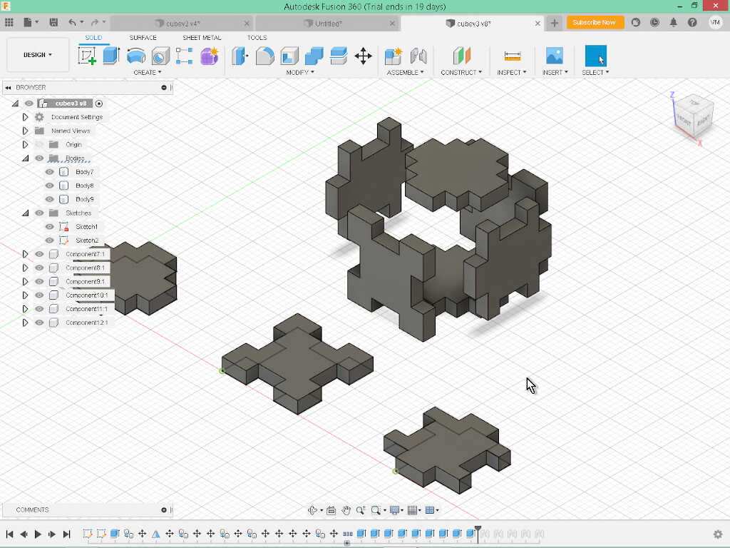
To put everything in place, I transformed all bodies into components, and used Assemble/Joint tool repeatedly.
Now, I need to export a vectorial picture so that the parts can be engraved on the laser cutter. First, I copied the 3 original bodies to a sheet parallel to the z axis just to have a reference. Then I transformed them in components, and added two auxiliary lines to aid me in aligning them properly, which I did afterwards, using the Modify/Align tool.
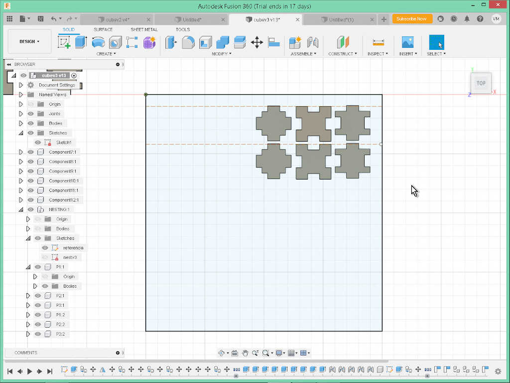
With the pieces aligned, I proceeded to create the sketch. I chose the plane of the reference sheet I mentioned before and clicked on the Create/Project/Include/Include 3D Geometry tool and chose the six components so that a sketch was drawn from the 2D sections, seen from the top.
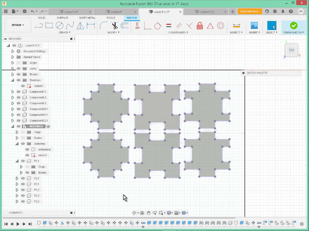
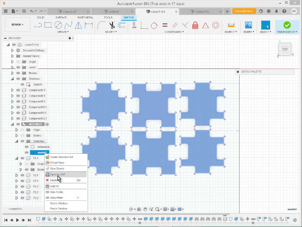
Then I simply right clicked on the sketch and saved as DXF.
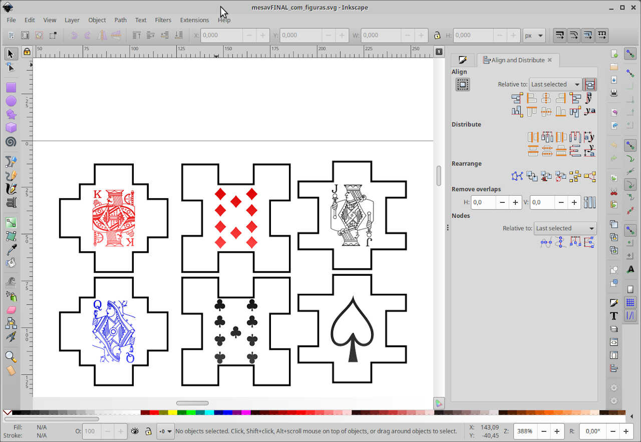
From here I left Fusion and opened Inkscape, and used the File/Import tool to import the DXF without changing the scale of the file. At the same time, I searched on the web for poker vectorial faces and found the ones I wanted on an open clipart repository, openclipart.org.
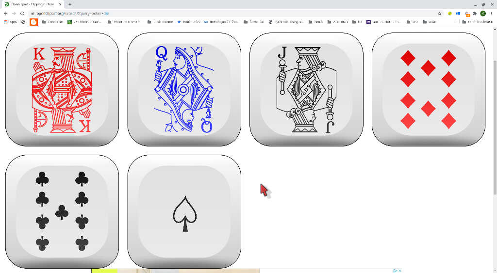
I disassembled them and I imported the svg the same way I imported the DXF into Inkscape. Then I aligned the pictures with the sketch and the end result can be seen in the following picture.
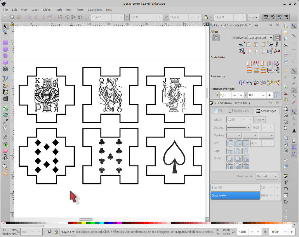
NOTE: To use the Epilog Model, the strokes for cutting must have a width of 0.0254 mm and the strokes for engraving must have a greater value that the one for cutting.
After printing on the laser we obtained the following result
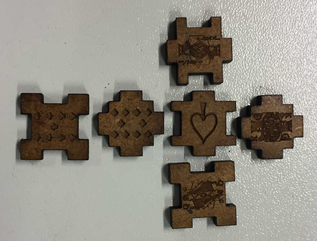
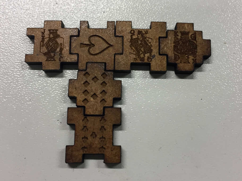
The press fit did not work! :( But at least we can invent a new domino game… ;) After thinking about it for a bit, I think the design is not taking into account the kerf properly, so I went back to the sketching board…and found out that indeed the kerf was missing from the difference between male and female press fit connectors!
The SVG file can be downloaded here and the new one yet to be cut here.
The fusion 360 STEP file can be downloaded here.
Laser Calibration…again!
From this point on I moved to another fablab, VivaLab to finish my lasercut designs.
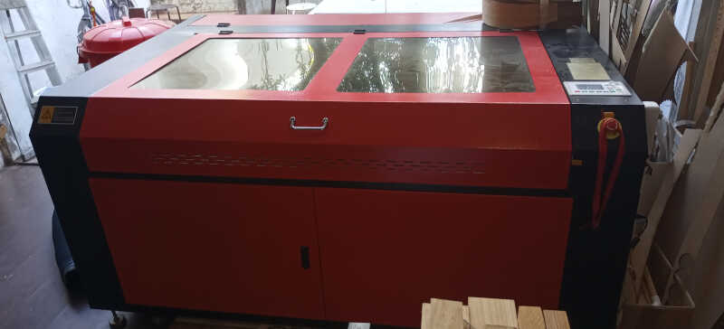
So with a new machine in hands, a 150 W generic chinese brand, shown below, I had to make the calibration of the kerf and focus.
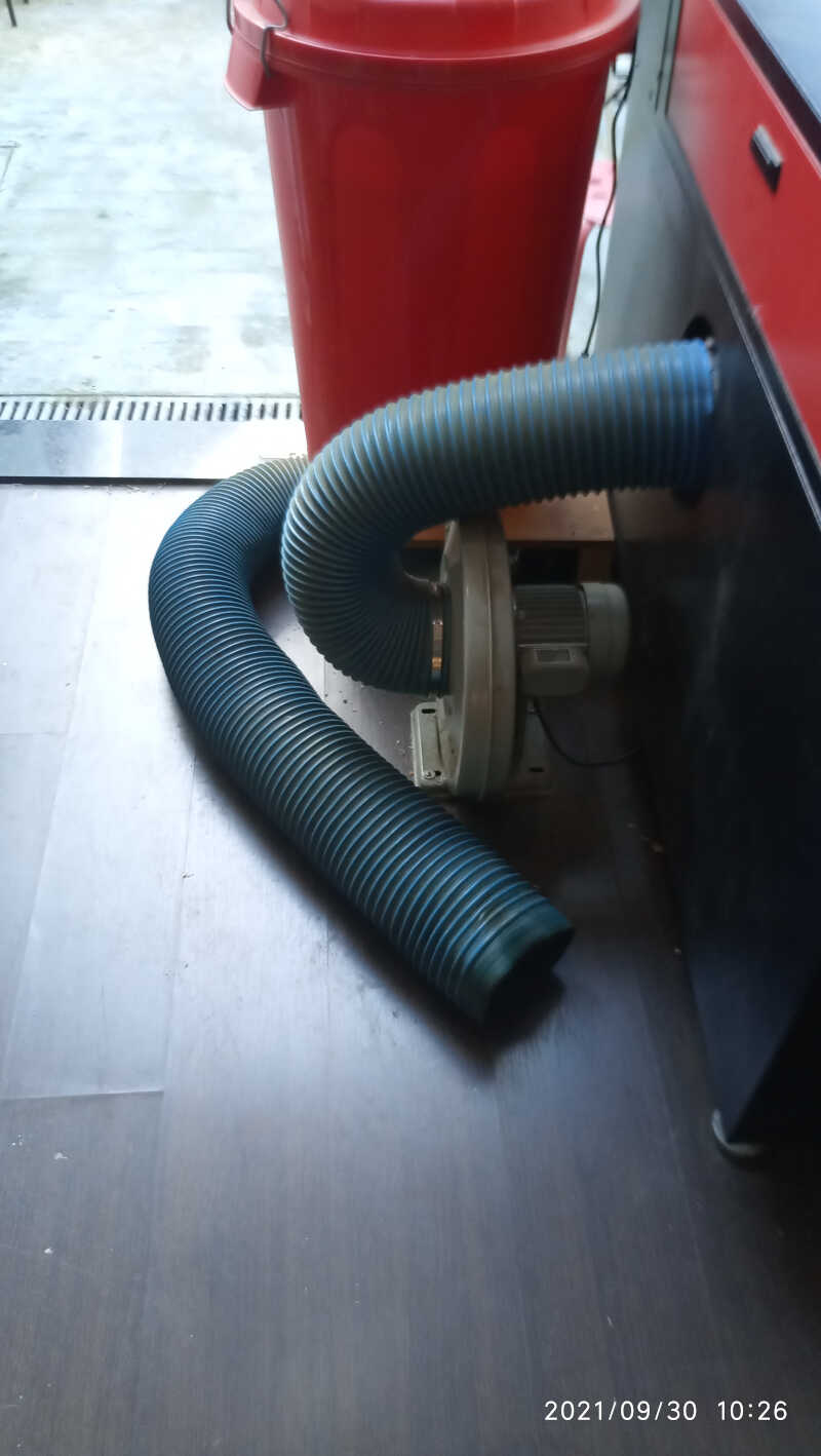
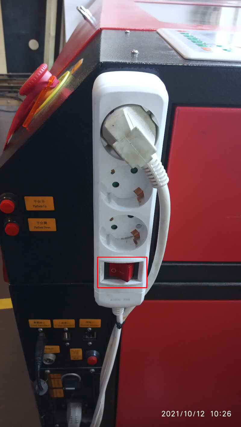
First of all I place the exhaust tube outside…
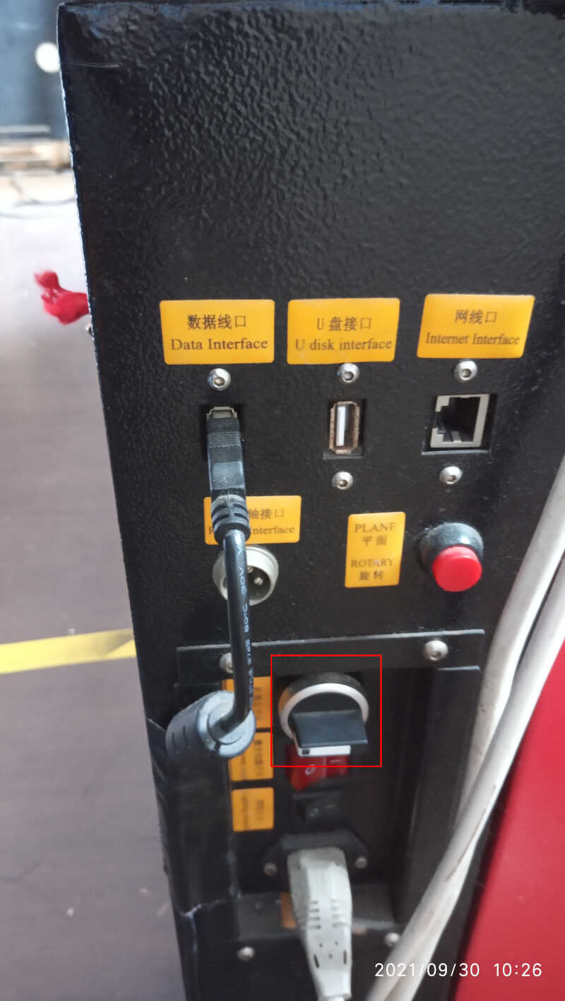
…turn the knob on the right hand side of the machine, depicted inside the the red square, to turn on the laser systems and air circulation…
…and check the focus. To do this I placed a calibration rod between the material (in this case 2.4 mm mdf(????)) and the laser nozzle as shown in the picture…
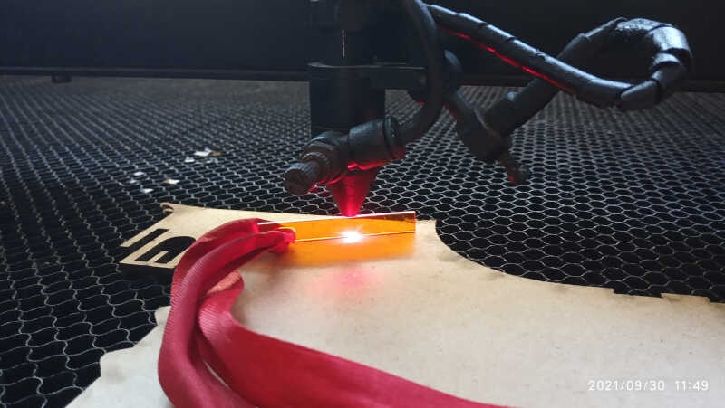
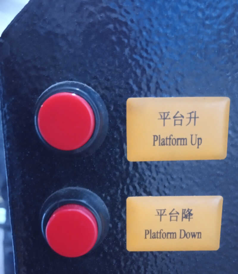
…and moved the table up and down, using the buttons on the right hand side of the table, until a little attrition is achieved when scratching the rod on the nozzle.
From here we will import a calibration .dxf file to check the behavior of the machine at certain speeds and powers as well as doing the kerf test.
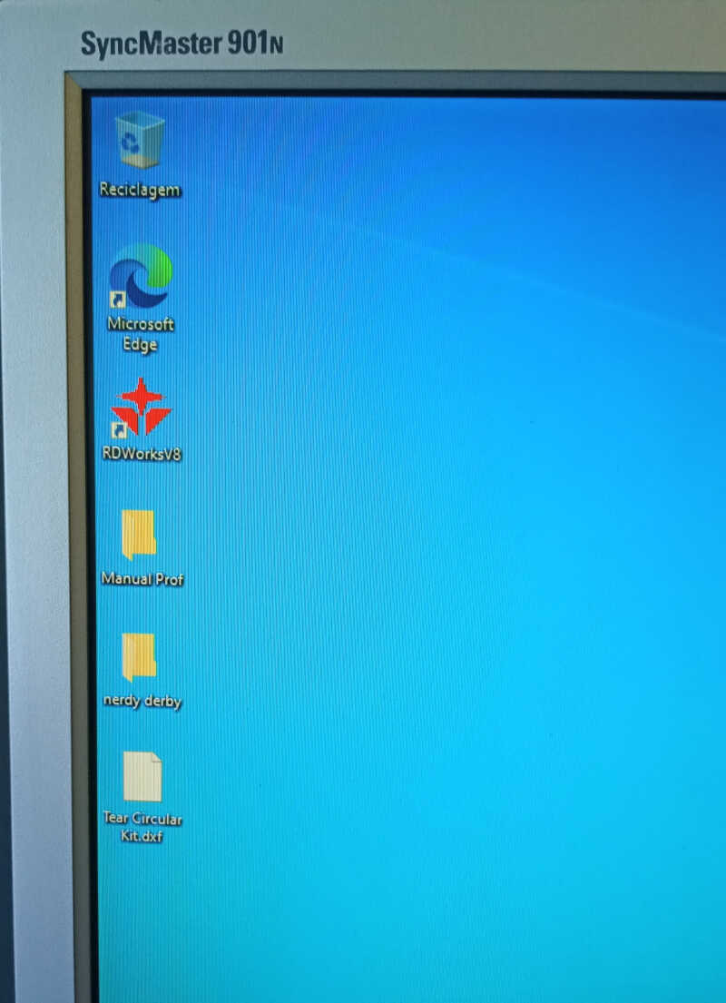
To add the test I opened the program that I will use to control the laser cutter, RDWorksv8.
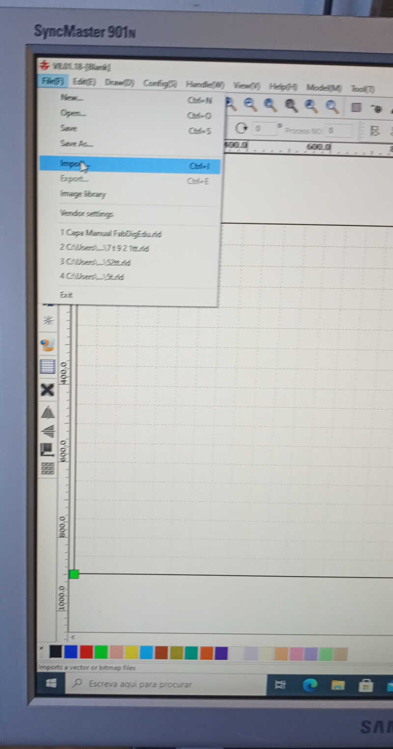
In file I used File/Import…
…and then color coded all the section according to the written speeds and laser power and hit Start [PRECISO REPETIR ISTO PORQUE ERA EM MODO ENGRAVE]
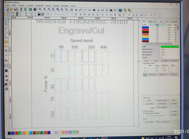
For the kerf test I used 9 rectangles of material which corresponds to 10 cuts. as shown at the bottom of the image.
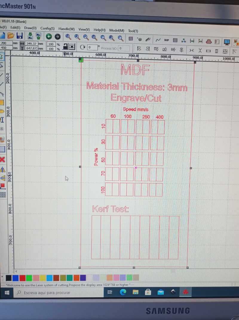
The kerf test section was cut using the following settings: velocity: 25m/s; power: 75 to 85%.
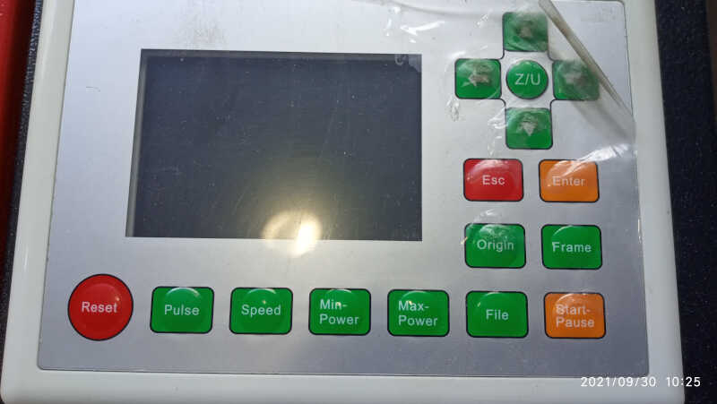
At this time, I could use the keyboard on the top of the machine to guide the laser nozzle to the correct place on the mdf board.
LAST BUT NOT LEAST it is necessary to turn on the water cooling!!
Now we can start.
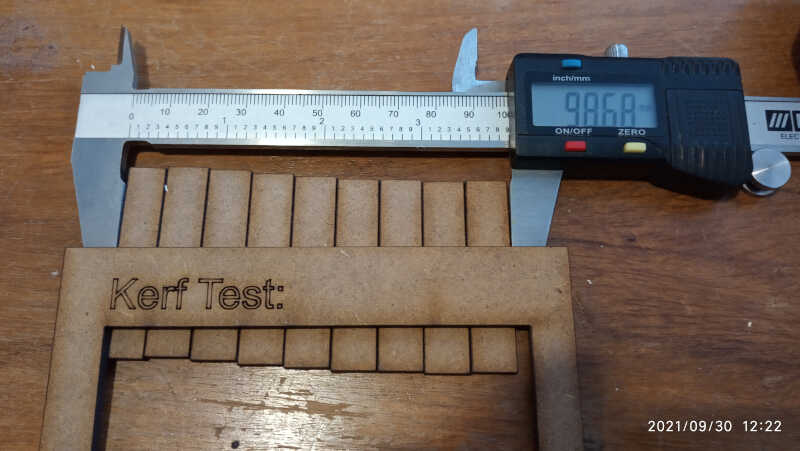
Here we can see the results for the engrave test…

and the measurement for the kerf test, shown in the picture below, giving a total of 98.68 mm which gives a difference to 100 mm of 1.32 mm. Despite this result we will consider in the designs a more conservative kerf of 02. mm.
A very small poker die part 2
I will keep things short so I will not repeat the section written before about the poker die. I will just place here the pictures of the new design…
…and the parameters I used…
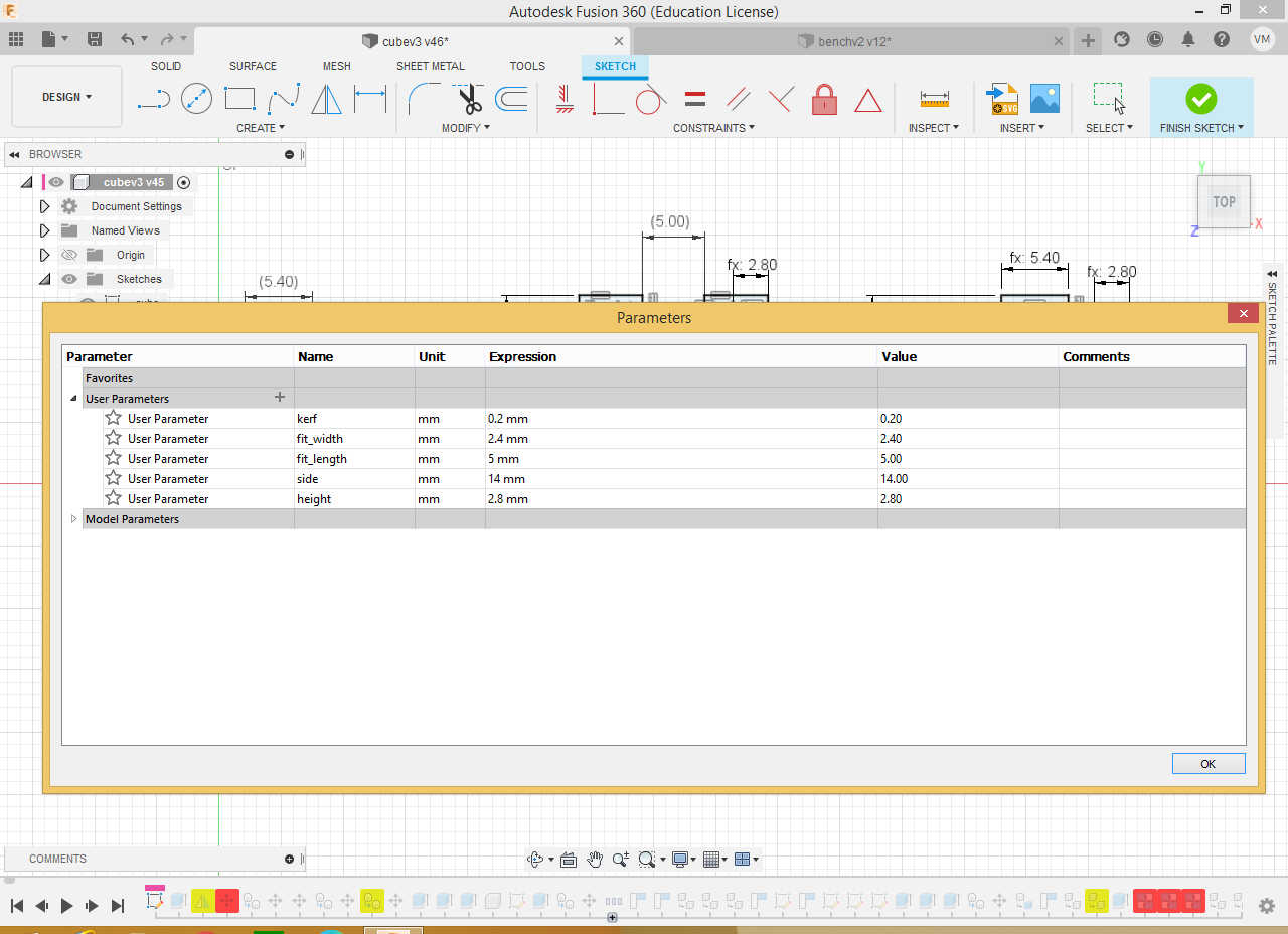
The snap fit is composed of a 5.4mm male and a 5.0 mm female to take the kerf into account, which is estimated to be around (but less than) 0.2 mm. The height of the cube piece is set to 2.8mm instead of 2.4 mm so that it can accommodate the kerf…
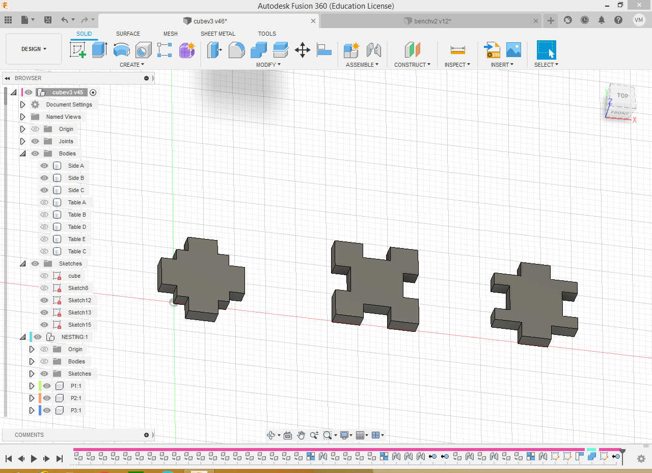
…and make the pieces fall exactly in place as shown in the following picture. The three original bodies were copied and transformed into components twice and assembled from and to appropriate edges with the assemble/joint tool. Note that there is a slight superposition to account for the kerf.
Then I put the little poker figures inside each tile as shown before…
…and exported them as .dxf.
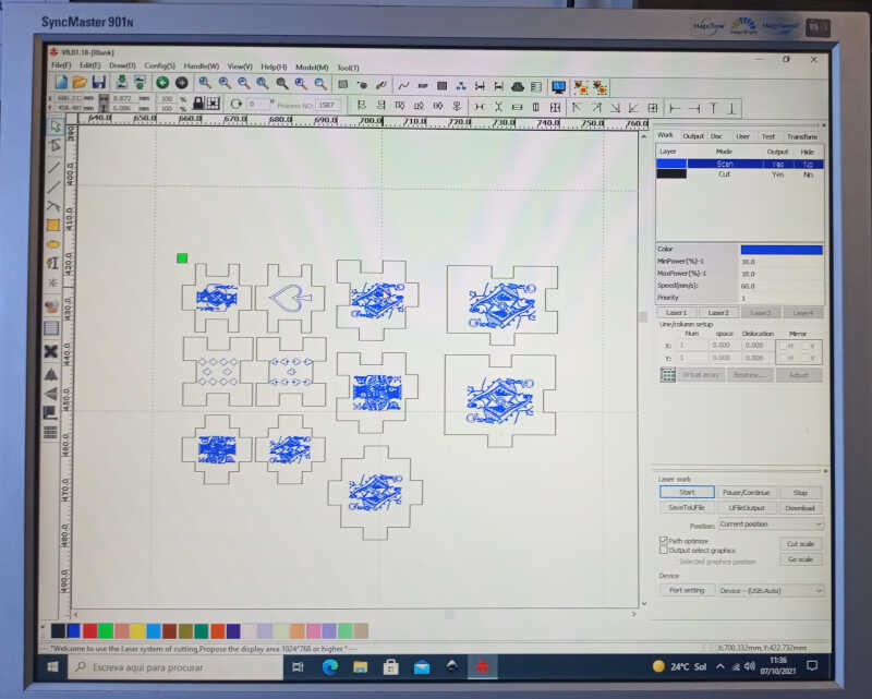
I took the file to the RDWorksv8…(the picture has some more parts, I will explain them later on!) and use the following parameters:
- first to scan the figures @ 60mm/s and power @ 10%. (in blue)
- then to cut the 2.4 mm mdf @ 25mm/s and power between 75 to 85%. (in black)
Finally, I clicked on Start and voilá…
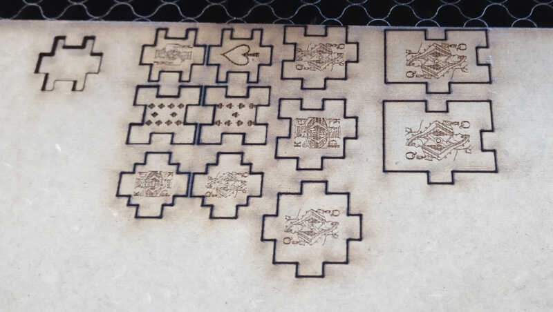
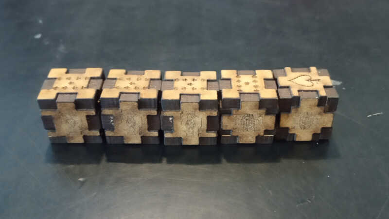
After some effort one cube is assembled..
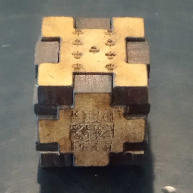
And then five cubes! All well press-fitted thank the gods.
The poker table
If you want to play poker dice you need a nice table! So I made one out of little poker pieces ;)
Back to Fusion 360 I designed the following parts…
…and created 2.8 mm height bodies.
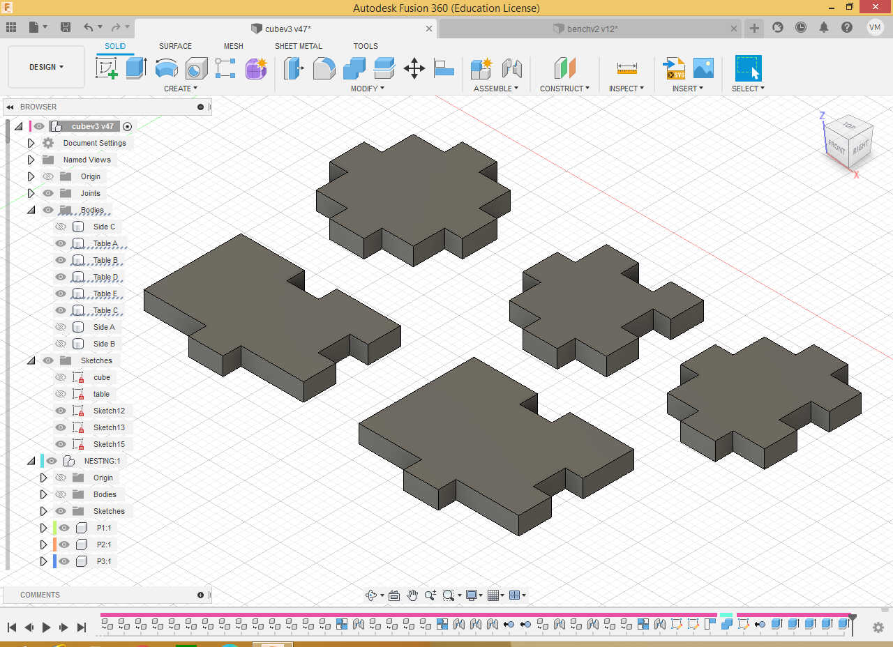
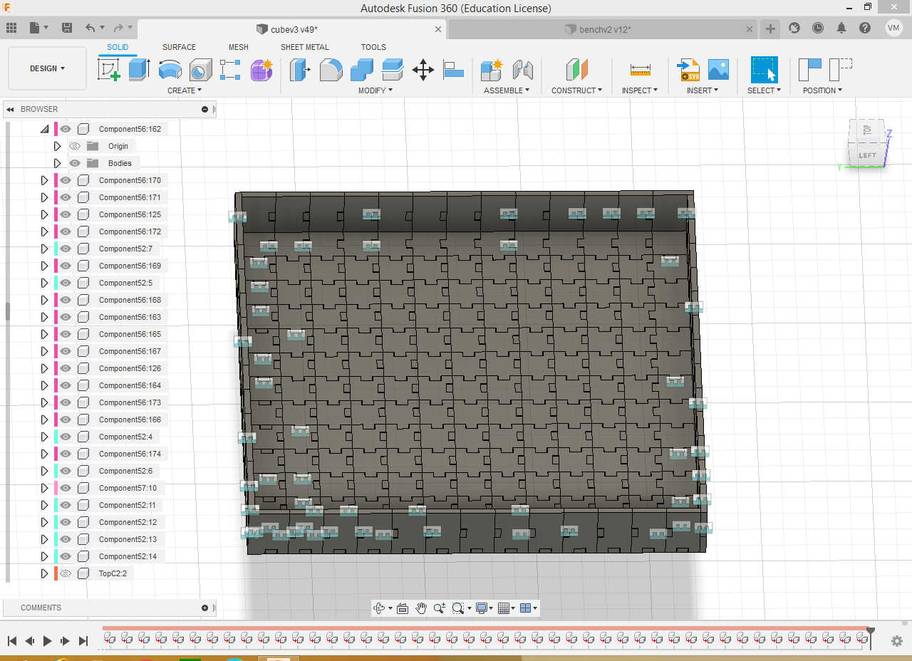
Finally, after A LOT of copying and pasting I got this pretty table ready to print!
After some scanning and cutting
I obtained a lot of little pieces that I could slowly assemble, as shown in the following pictures…
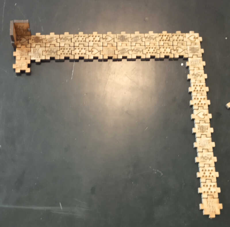
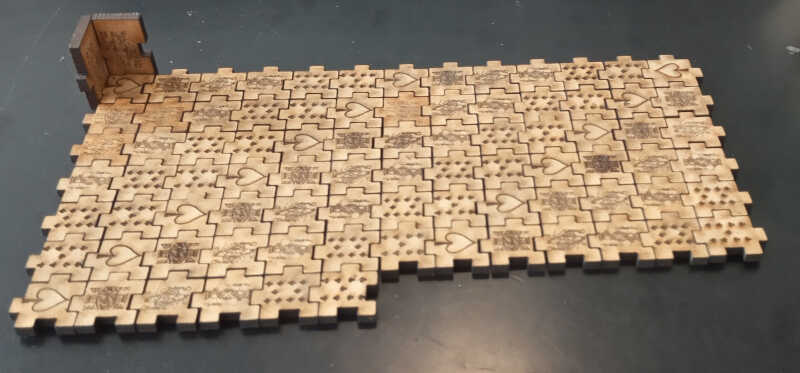
And finally the complete table!
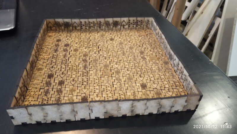
Fancy for a game of poker dice? ;)