15. Wildcard week
A qualitative description of a Fabulaser Build
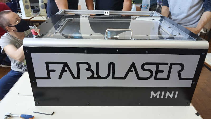
My wildcard week was suddenly rocked by an important task we had to do here at Fablab Benfica: the build of a [Fabulaser Mini] 40 W laser cutter. This task is also critical to complete my Fab Academy week 03.
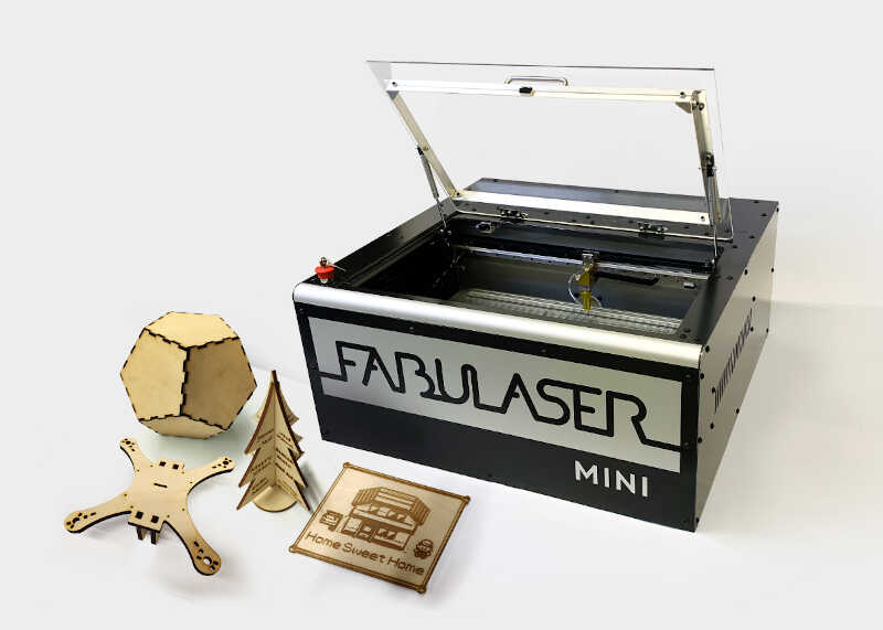
The following move was taken from the fabulaser page and shows an example of what we can achieve with this machine in terms of cutting power and precision.
This build was done in three days (thursday, wednesday, and friday) and took more than 20h. It was coordinated remotely by Daniele Ingrassia the creator of Fabulaser from [Fablab Kali] in Germany.
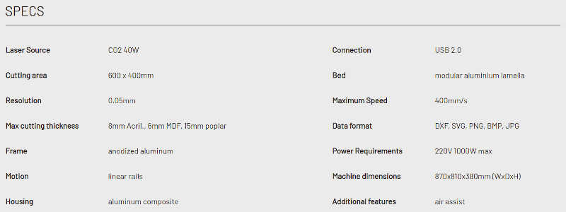
The Fabulaser specs can be read in the picture below
I will do a qualitative description of events due to lack of time.
Day zero
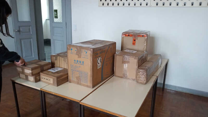
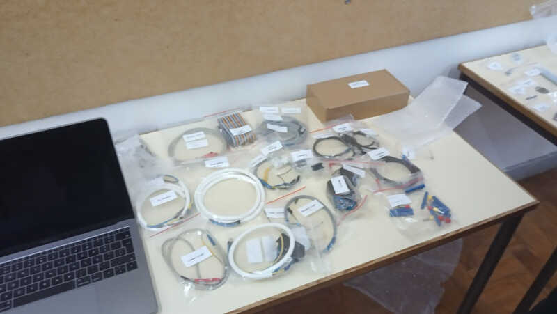
One day before starting, we brought everything Daniele has sent to us to a room in [ESELx]. The packages are shown in the following picture.
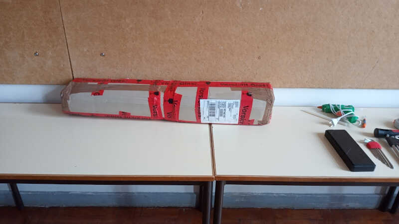
…and here is the CO2 Laser detached for the world…
Day one (Thursday the 13th from 18h to 21h30)
Are you ready? :)
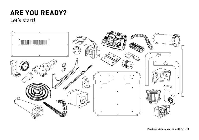
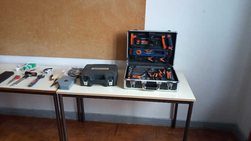
We started day 1 by organizing our basic tools…
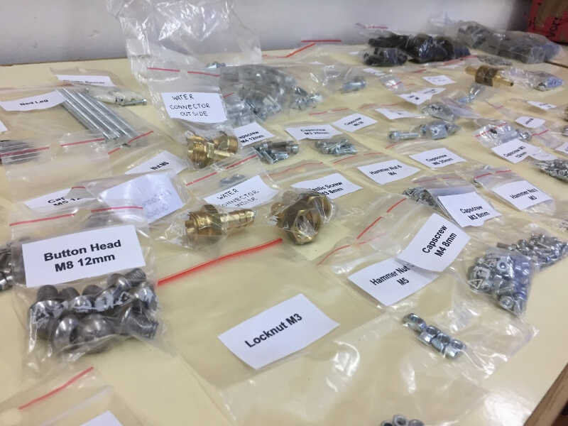
…and all the components…
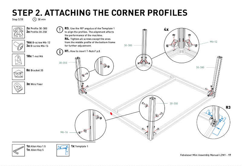
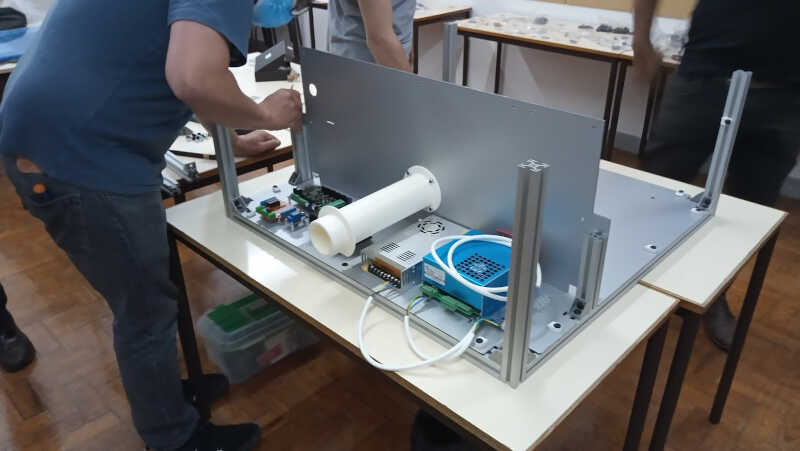
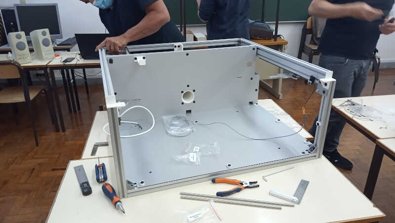
Then we continued by assembling the bottom frame and its corner profiles…
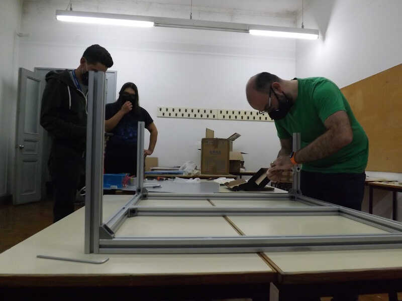
…according to the instruction from the beta version of the laser cutter’s manual.
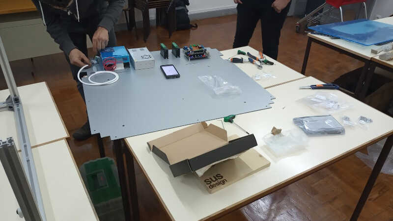
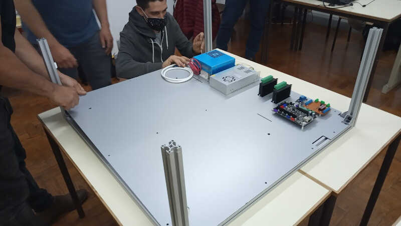
At the same time the bottom panel containing the electrical part and the control part was being assembled as well.
 The bottom panel, is then attached to the bottom frame.
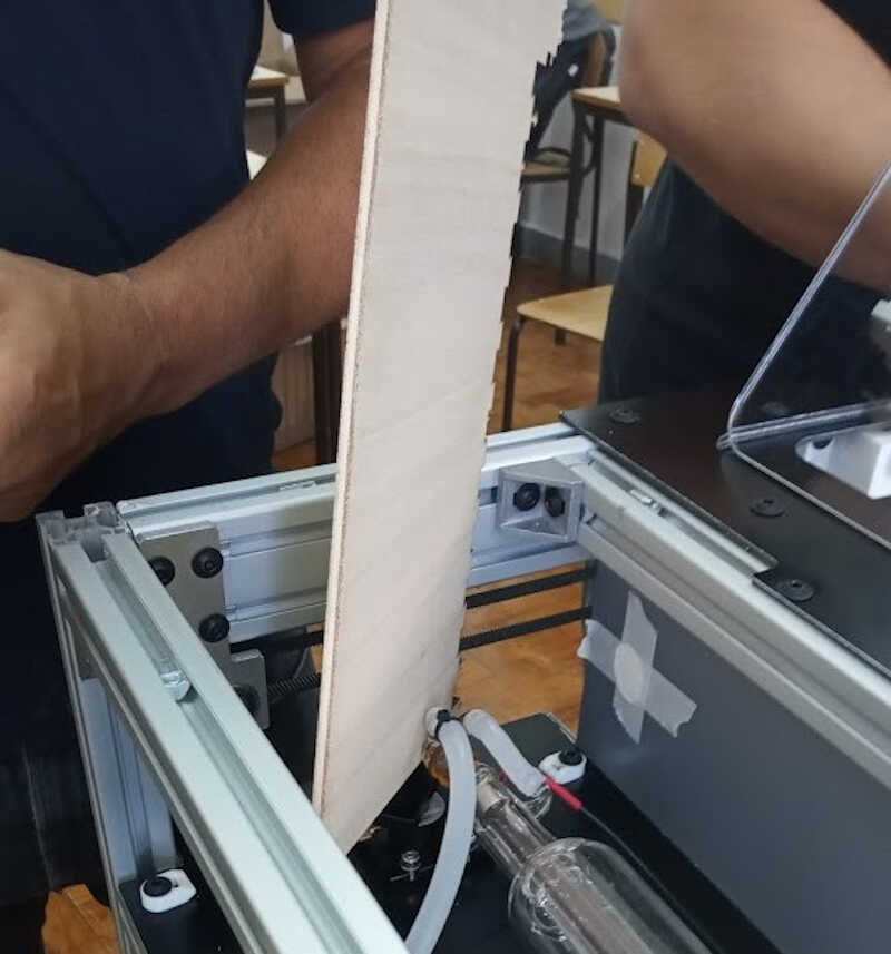
Then we installed the separator plane and the exhaust tube. And that was it for thursday night.
Day two (Friday the 14th from 16h30 to…)
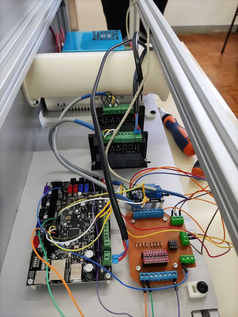
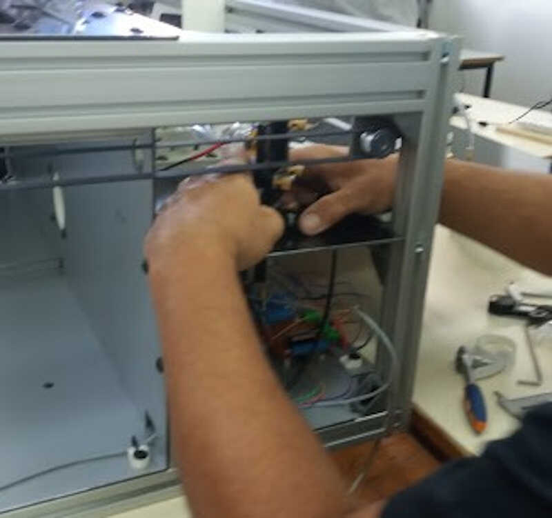
On friday, we starte to wire the power and the logic circuits. I will not show here the wiring diagram as there are two versions and the manual needs to be updated.
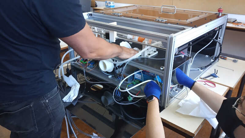
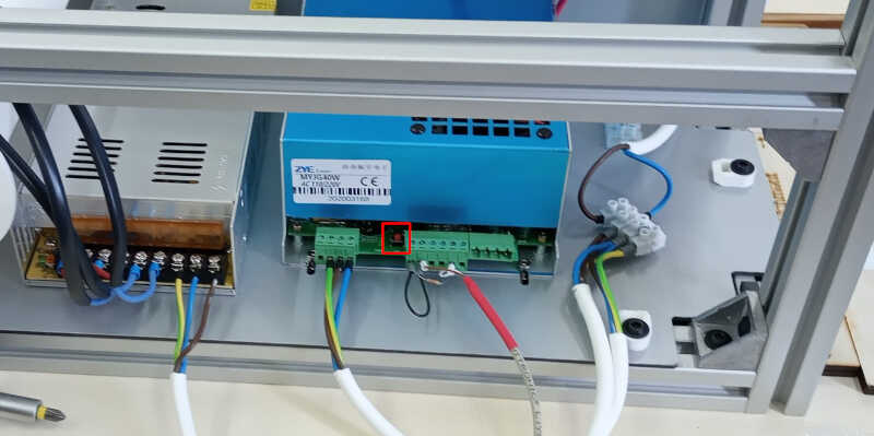
The next picture shows the logic circuits in the foreground and the stepper motor circuits in the background.
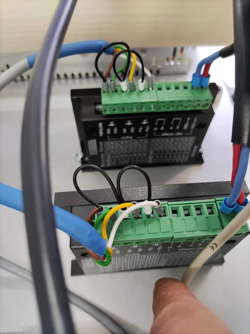
Here, the stepper motor circuits can be seen in more detail.
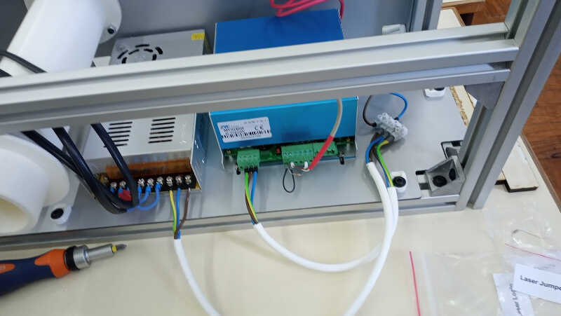
And the PSU units electrical circuit.
Then we built the laser panel profile and the laser panel, which will hold the laser source.
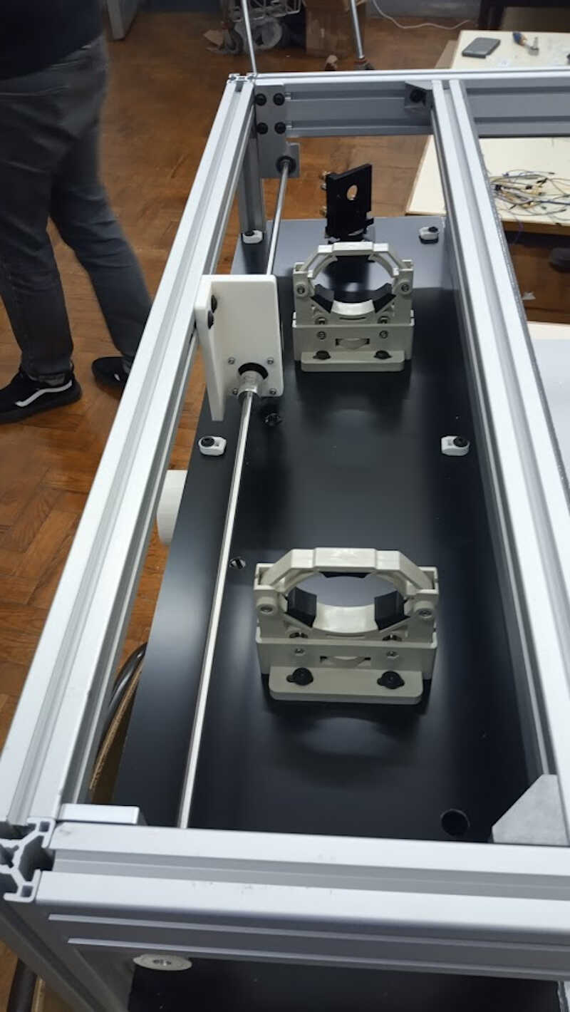
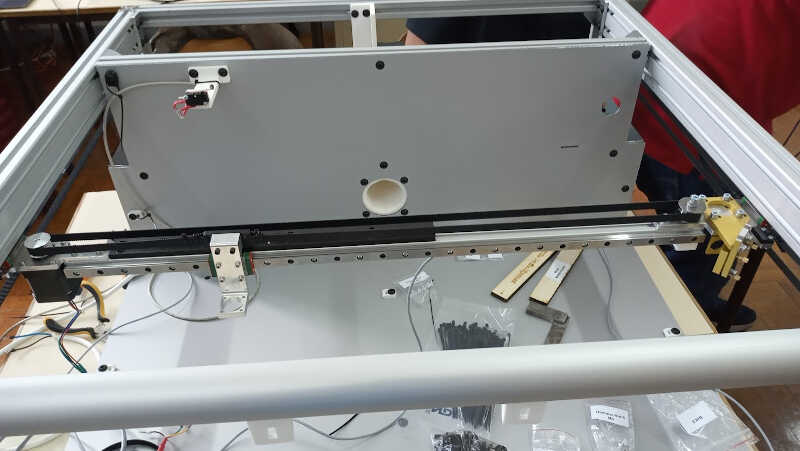
Here we can observe the y axis construction, with its holders…
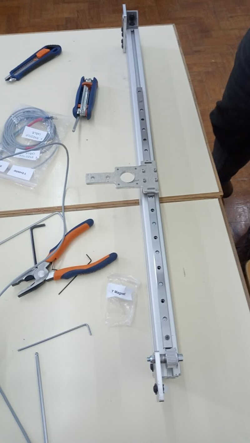
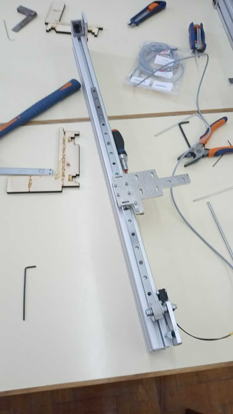
…and the Y axis already in place in the frame of the machine.
At the same time, another team installed the laser path on the back of the machine and the y axis motor installation…
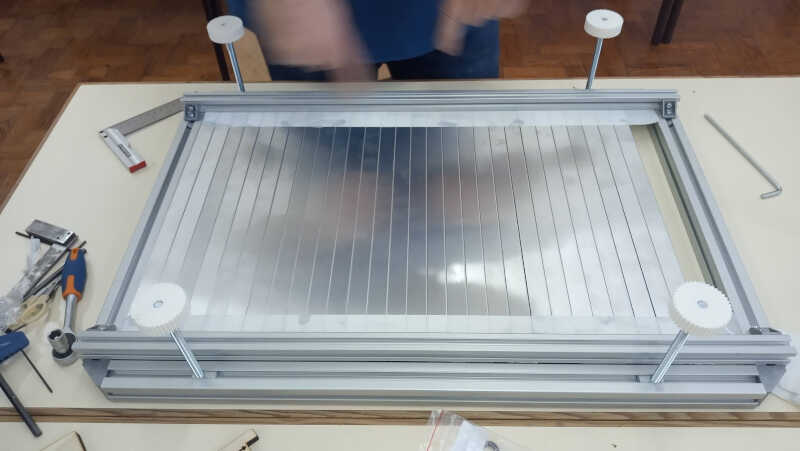
…and the bed frame and support was also built.
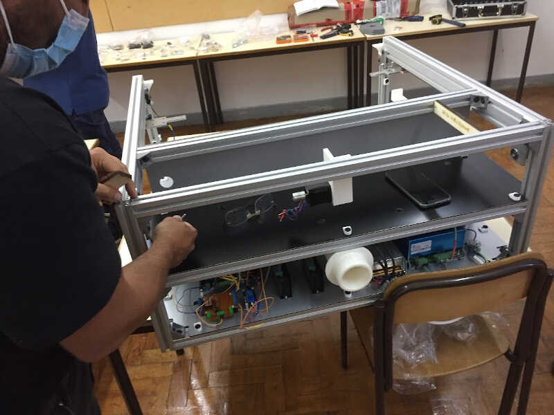
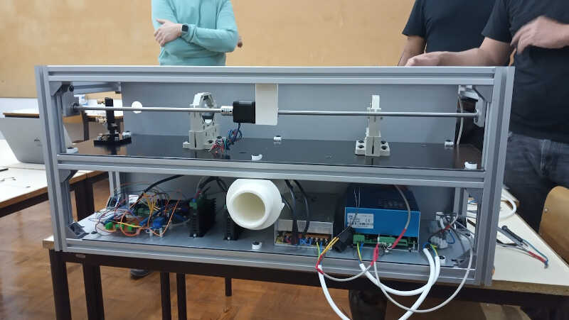
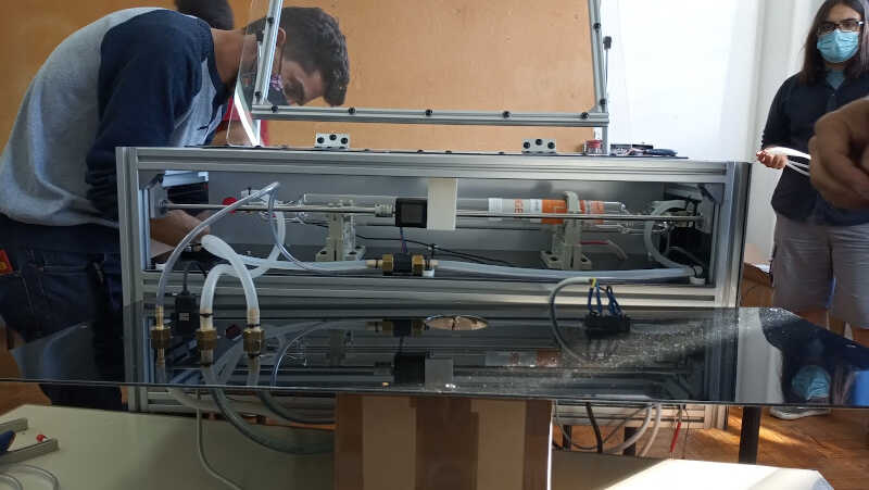
Ok…the back of the printer has almost all components installed except for the CO2 Laser.
Day three (Saturday - from 9h00 to 00h30!)
The last day was the most intense one. We had a problem with the water hoses and it delayed our build a few hours, so the session extended and lasted until 00h30!
We started with the X axis installation and followed the instructions of the manual, as shown below as an example
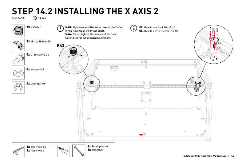
And here is depicted the X axis already in place. At this point we didn’t have any more manual to follow, so we carefully heard the instructions given by Daniele at each additional step of the process.
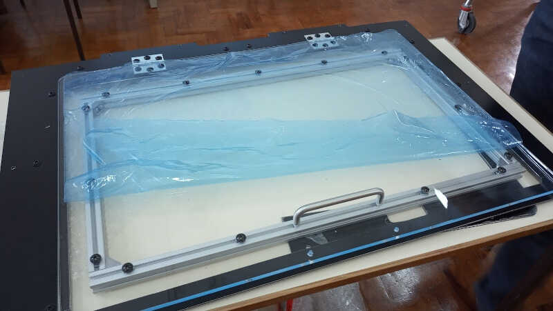
Another step involved building the bed cover which includes a lid.
The next picture shows the bed cover with lid before being installed in the bed…
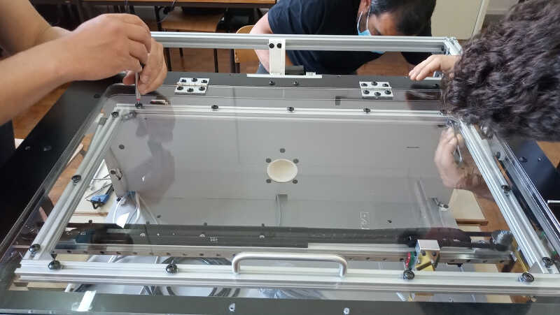
, the cover put in place…
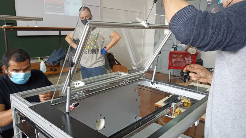
, and the cover with the lid open!
We also installed the front panel. Now it looks like a proper, fabulous laser cutter!
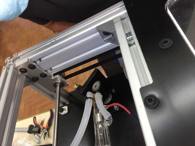
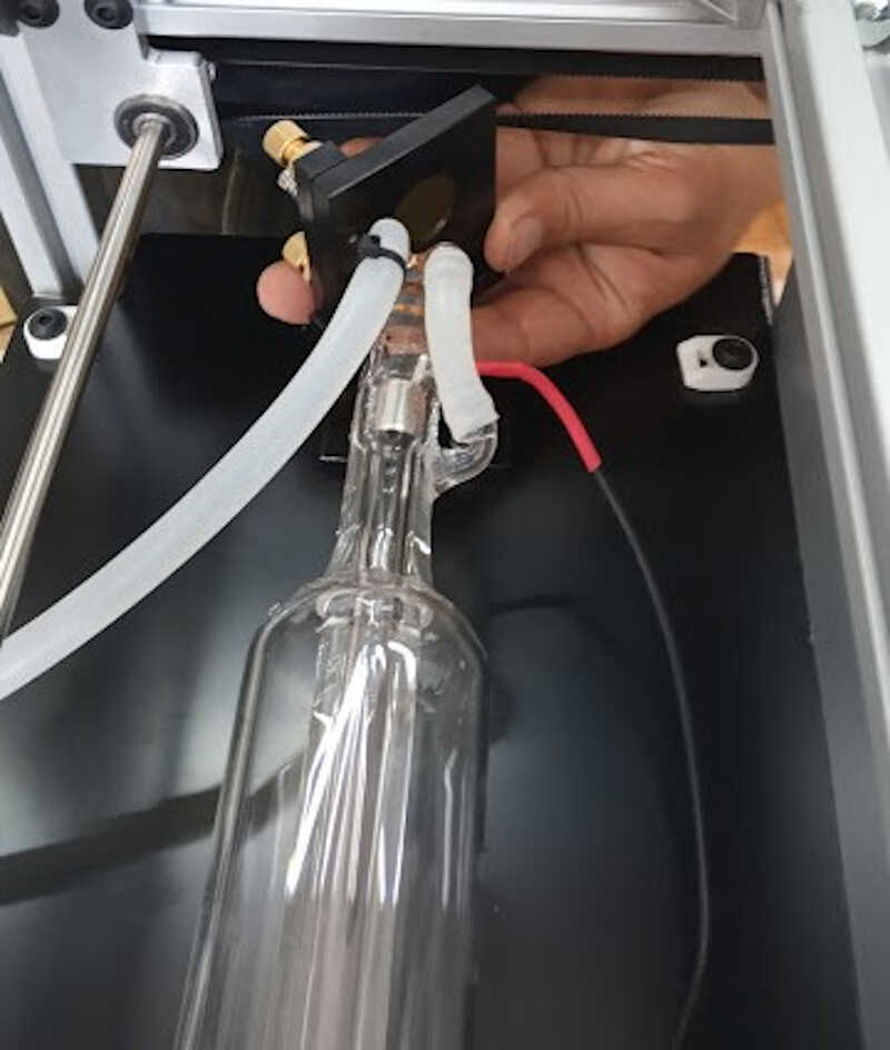
Finally, we installed the laser tube in its place…
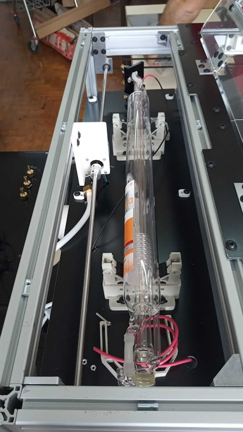
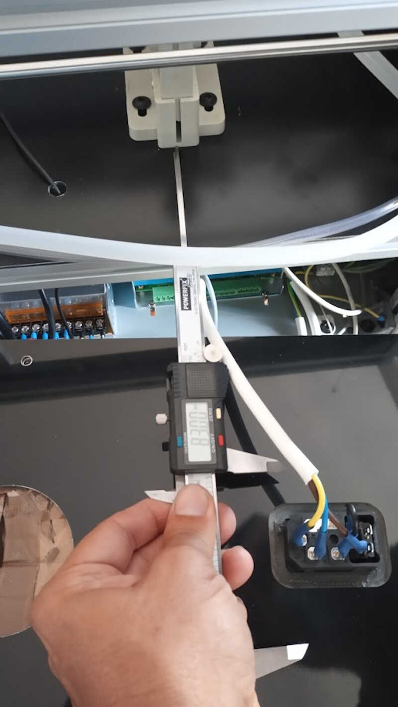
…and connected the water circuitry needed to collect the heat from the tube when it fires. In the next picture we can observe the installed water circuit (the chiller is not visible) and the back cover, with the connection to the mains already established.
Ok…so when we installed the laser tube and plugged the water circuit we immediately saw a very strange behavior inside the tube: there was some kind of dust building up on the walls of the tube!
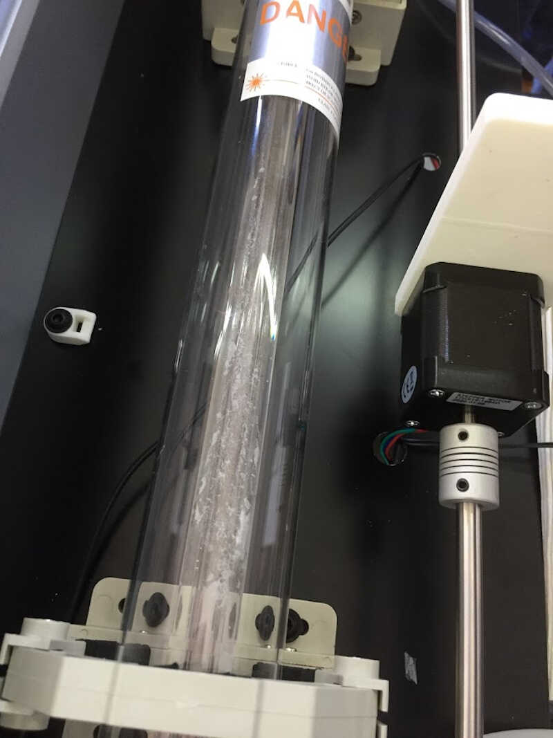
What was the origin of this dust? Seems that the hoses came coated with some anti-friction (?) powder, as shown in the video below. It was the first time it happened so Daniele was going to check with his supplier about what had happened.
So, when we tried to shake the tube to see if the dust could come off, one of the pipes in the back of the tube got loose and filled the laser tube stage with water :O. Some of the water also crept to the structure and to the ground floor near the electronics and electrical parts. This was a huge scare! And we had to dry the power source. The rest of the electronics didn’t get any water.
In fact it happened two times! :O So we had to secure the hoses with nylon clamps.
After this we removed the the laser glass container and moved it a bit to see if the dust would disappear.
Unfortunately the dust was not removed. We thought this laser was over but it was not the end of it yet ;)
We decided to clean the glass walls with detergent. This would take a few hours but it was the way we thought was best.
So we made a circuit only with the tube and the chiller…
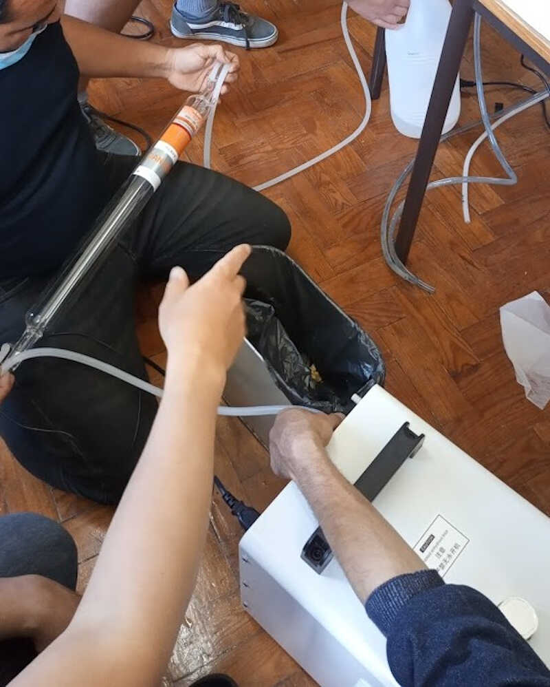
…and introduced a bit of detergent.
The result is shown in the following video
Of course, then we had to remove the detergent from the chiller and that took a long time!
With that out of the way was time to calibrate the axes. As expected the traveled distances of the axes was calibrated and had pinpoint accuracy. Unfotunately, I don’t have any video os the axes moving.
The next step involves the calibration of the laser path, that needs to strike exactly in the center of the three mirrors of the machine. This was the longest part of the build.
Calibration zero
To speed things up, we took the data of the exact position of the tube in Daniele’s machine so we could establish a quicker calibration.
So we took the reference measurement for the horizontal placement of the tube, from the support to the edge…
…as well as its height.
Then, we tested if the tube was working. A small piece of plywood was placed near the laserhead and one shot was fired. It went well and the plywood was marked with a laser burn.
The laser is shot by quickly pressing the small red button on the laser’s power source.
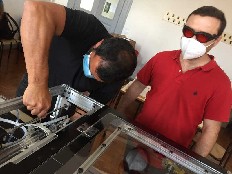
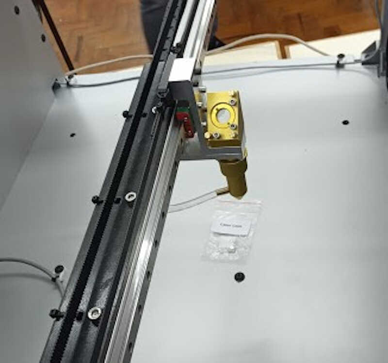
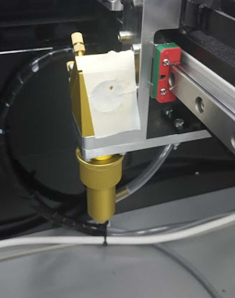
Afterwards we tested the first mirror placement by using painter’s tape in the place of the lens and check if the laser position was centered with the mirror hole center by shooting small laser impulses, and adjusted the laser accordingly.
Then, the first mirror was put in place…
as well as the other two mirrors and the cutting head.
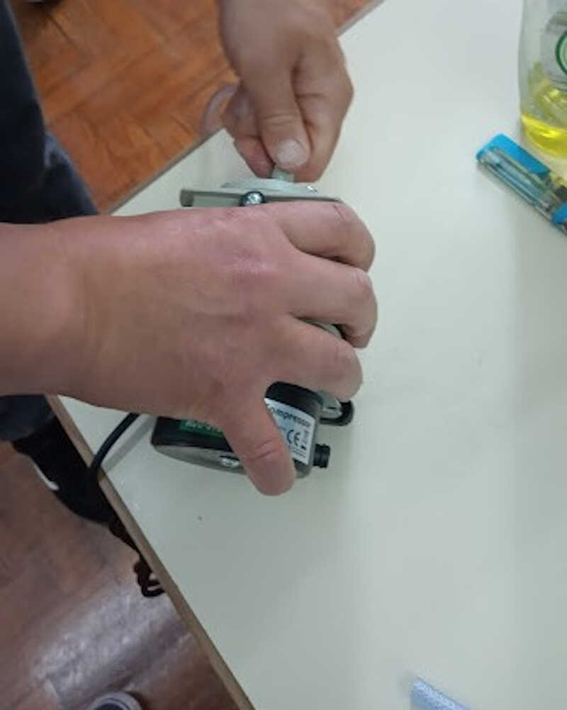
We also turned the air assist to control the cutting near the cutting head using a small air compressor.
Calibrating the first mirror
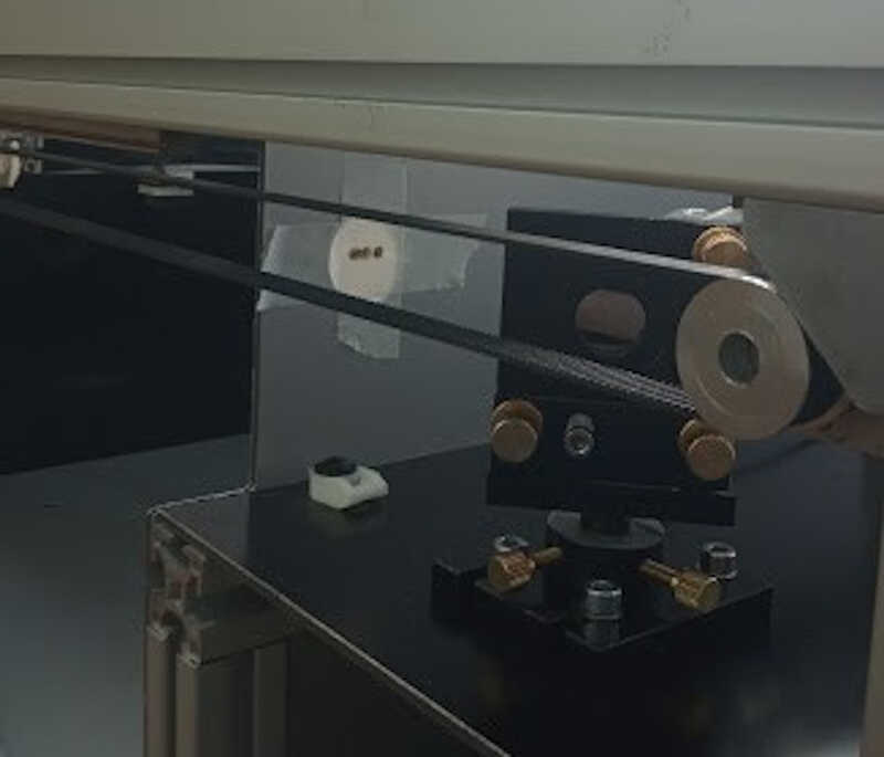
To calibrate our mirrors we used painter’s tape on the path of the laser immediately after the mirror. Never never place the tape on the lens as you can make it dirty it or even damage it!!!
[falta colocar como foram colocadas as lentes]]
We shot a very small laser impulse and checked where it burned the tape and then slightly adjusted the mirror a few times until it was centered.
If necessary, small adjustments were made by slightly rotating the gold knobs behind the mirror.
Calibrating the second mirror
The same procedure was used to calibrate the second mirror
Calibrating the third mirror
[PRECISO FALAR COMM O LUCIO]
Finally we tested the third mirror with a live test on a plywood frame. As can be seen from the video, the laser needs some focusing!!! Looks more like a flamethrower!!! :)
After some adjustments [ver com o lúcio] we could draw a perfect circle with a focused laser beam!
First test
The first real test was to cut the logo of Fablab Benfica, following the strict orders of the Maestro Danielle! :) All went well :)
TBD
- Closing the laser sides - DONE
- Connecting the laser cutter to the exhaustion system
- Finishing week03 :P
Fabricating a cover with a thermoforming machine
For the wildcard week I’ll be doing a part for my final project with a Mayku Formbox](https://www.mayku.me/) using a CNC machined mold.
In the picture below there’s an early version of this mold, still in the design phase. It misses the gap for the air to flow through the device. A detailed explanation will follow once it is being fabricated.
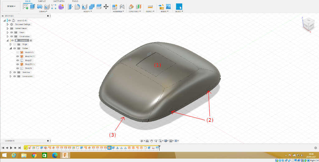
The (1) depicts the place here the OLED screen will be installed. The (2) shows the positions of the holes for the snap/press fits which will attach to the base. The (3) is a little extra 3mm portion of the material which is added so that the thermoforming process does not bend the piece, and will be cut afterwards.