14. Embedded Networking and Communications
Group assignment
For this group assignment we wanted to connect 2 boards with serial connection. This only needs 2 wires between the boards. You can send data back and forth between different boards if you connect the RX and TX pin of the boards.
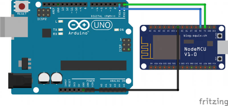
THis can be any board with TX and RX pins available. Make sure you cross connect them. The TX pin from board 1 goes to the RX pin of board 2. and vice versa.
- RX == receive
- TX == transmit sender_pic.jpg
For code we based our demo on this info found on the arduino forum. https://forum.arduino.cc/t/sending-multiple-values-between-two-arduino-serially/401278
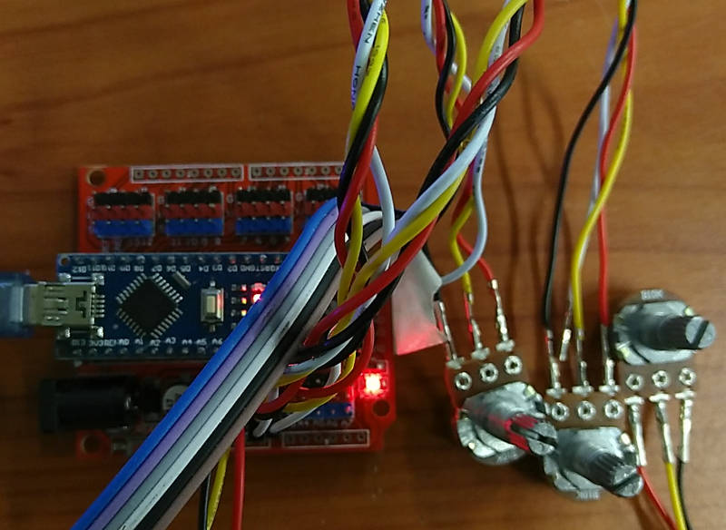
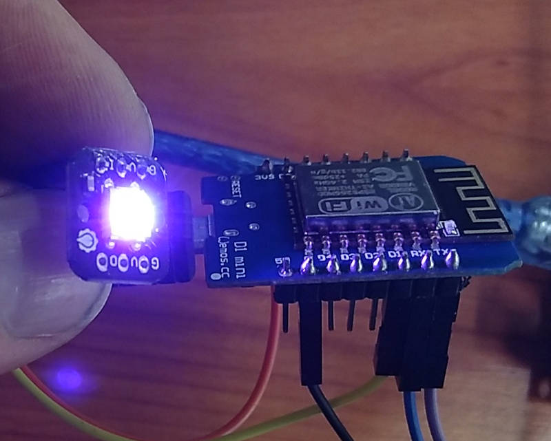
We wanted to make an RGB led controller with 3 potentionmeters on the arduino board. (this is based on the Virtualcolormixer example that comes with the arduino IDE) Data from the analogRead of the potentiometers is send via Serial to the Wemos D1 board. This board has a Neopixel and changes color based on the data received.
A screenshot of the sender code and serial output
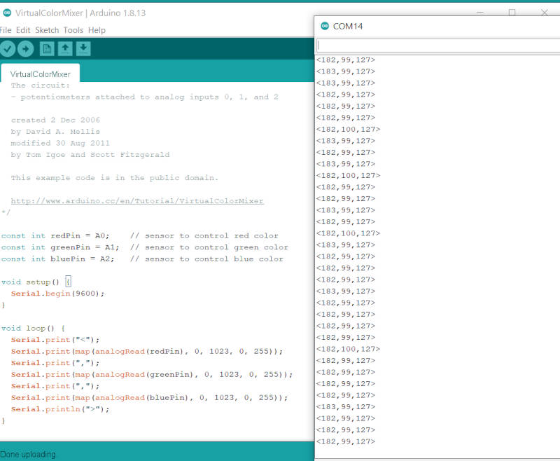
The sender code is minimal. We use a start and end character to be more consistent in decoding the receiving data later.
 Serial.print("<");
 Serial.print(map(analogRead(redPin), 0, 1023, 0, 255));
 Serial.print(",");
 Serial.print(map(analogRead(greenPin), 0, 1023, 0, 255));
 Serial.print(",");
 Serial.print(map(analogRead(bluePin), 0, 1023, 0, 255));
 Serial.println(">");
A screenshot of the receiver code and serial output
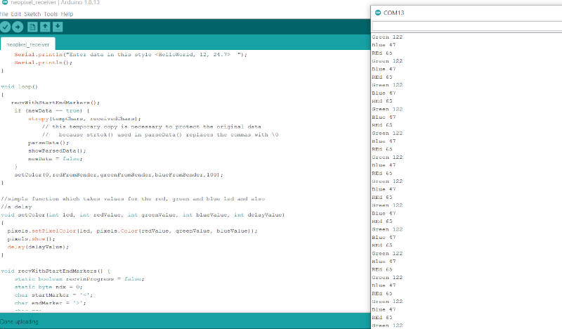
The receveiver code has some functions to parse the incoming data. And look for: ‘<’ and ‘>’
 void recvWithStartEndMarkers() {
     static boolean recvInProgress = false;
     static byte ndx = 0;
     char startMarker = '<';
     char endMarker = '>';
     char rc;

     while (Serial.available() > 0 && newData == false) {
         rc = Serial.read();

         if (recvInProgress == true) {
             if (rc != endMarker) {
                 receivedChars[ndx] = rc;
                 ndx++;
                 if (ndx >= numChars) {
                     ndx = numChars - 1;
                 }
             }
             else {
                 receivedChars[ndx] = '\0'; // terminate the string
                 recvInProgress = false;
                 ndx = 0;
                 newData = true;
             }
         }

         else if (rc == startMarker) {
             recvInProgress = true;
         }
     }
 }
The parseData funcion splits the received chars into parts based on the ‘,’ in between values.
Video of the whole thing working:
Code Files
Individual assignment
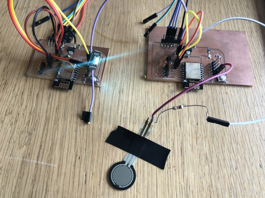
The embedded networking assignment will be an assignment between my two (identical) boards I made for the input and output weeks.
The one ESP module has the RGB led attached and the other module has the Force sensitive resistor. The goal is to use the input generated from the FSR to make the RGB led on the other board change color.
In orde to achieve this, one ESP board has to become a sender and the other a receiver.
I followed the following tutorial from random nerds to get started.
Connect the boards
To allow the board to talk to one another you have to know the mac addresses, especially from the receiving board.
You can use this piece of code to read out the address in you serial monitor:
#ifdef ESP32
  #include <WiFi.h>
#else
  #include <ESP8266WiFi.h>
#endif

void setup(){
  Serial.begin(115200);
  Serial.println();
  Serial.print("ESP Board MAC Address:  ");
  Serial.println(WiFi.macAddress());
}

void loop(){

}
Now that you have the mac address of your board, you can programme the sender to communicate with the receiver.
Set up the sender
Pick the board you which to become the sender. (Check that you have selected the right serial port for progamming the board in case you have both connected!)
For me the sender will be the board with the FSR connected on the right
The goal is to build on the code I previously used during the input week and send the generated values to the receiver on the left.
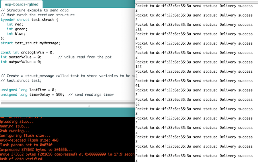
I used the following code. It’s an adapted version from the code in the tutorial on random nerds.
/*
  Rui Santos
  Complete project details at https://RandomNerdTutorials.com/esp-now-one-to-many-esp8266-nodemcu/

  Permission is hereby granted, free of charge, to any person obtaining a copy
  of this software and associated documentation files.

  The above copyright notice and this permission notice shall be included in all
  copies or substantial portions of the Software.
*/

#include <ESP8266WiFi.h>
#include <espnow.h>

// REPLACE WITH RECEIVER MAC Address
uint8_t broadcastAddress1[] = {0xDC, 0x4F, 0x22, 0x6E, 0x35, 0x3A};

// Structure example to send data
// Must match the receiver structure
typedef struct test_struct {
   int red;
   int green;
   int blue;
};
struct test_struct myMessage;

const int analogInPin = 0;
int sensorValue = 0;        // value read from the pot
int outputValue = 0;


// Create a struct_message called test to store variables to be sent
// test_struct test;

unsigned long lastTime = 0;
unsigned long timerDelay = 500;  // send readings timer

// Callback when data is sent
void OnDataSent(uint8_t *mac_addr, uint8_t sendStatus) {
  char macStr[18];
  Serial.print("Packet to:");
  snprintf(macStr, sizeof(macStr), "%02x:%02x:%02x:%02x:%02x:%02x",
         mac_addr[0], mac_addr[1], mac_addr[2], mac_addr[3], mac_addr[4], mac_addr[5]);
  Serial.print(macStr);
  Serial.print(" send status: ");
  if (sendStatus == 0){
    Serial.println("Delivery success");
  }
  else{
    Serial.println("Delivery fail");
  }
}

void setup() {
  // Init Serial Monitor
  Serial.begin(115200);

  // Set device as a Wi-Fi Station
  WiFi.mode(WIFI_STA);
  WiFi.disconnect();

  // Init ESP-NOW
  if (esp_now_init() != 0) {
    Serial.println("Error initializing ESP-NOW");
    return;
  }

  esp_now_set_self_role(ESP_NOW_ROLE_CONTROLLER);

  // Once ESPNow is successfully Init, we will register for Send CB to
  // get the status of Trasnmitted packet
  esp_now_register_send_cb(OnDataSent);

  // Register peer
  esp_now_add_peer(broadcastAddress1, ESP_NOW_ROLE_SLAVE, 1, NULL, 0);

}

void loop() {
  if ((millis() - lastTime) > timerDelay) {
    // Set values to send
    // test.x = random(1, 50);
    // test.y = random(1, 50);

  sensorValue = analogRead(analogInPin);
  outputValue = map(sensorValue, 0, 1024, 0, 255);
  Serial.println(outputValue);
  myMessage.red = random(0, 254);
  myMessage.green = random(0, 254);
  myMessage.blue = outputValue;//random(0, 254);

    // Send message via ESP-NOW
    esp_now_send(0, (uint8_t *) &myMessage, sizeof(myMessage));

    lastTime = millis();
  }
}
The sensor input reads like this in the serial monitor. As I only use one input, the data from the input is used to change the output value of the color blue in the RGB led.
Set up the receiver
With the sensor in place on the sender part, we need to make sure the receiver can receive and understand the data send.
For this we need to make sure we use the same names for the different variables. In my case this means the values for the RGB led.
It will read the data from the serial monitor for the blue led, the red and green will be random.
After a bit of tinkering with the code, this is the one I landed with.
#include <Arduino.h>
#include <ESP8266WiFi.h>
#include <espnow.h>
#include <Adafruit_NeoPixel.h>

#define PIN 13 //=wemos D1

Adafruit_NeoPixel pixels = Adafruit_NeoPixel(1, PIN, NEO_GRB + NEO_KHZ800);

typedef struct message {
   int red;
   int green;
   int blue;
} message;
message myMessage;


void onDataReceiver(uint8_t * mac, uint8_t *incomingData, uint8_t len) {
   Serial.println("Message received.");
   // We don't use mac to verify the sender
   // Let us transform the incomingData into our message structure
  memcpy(&myMessage, incomingData, sizeof(myMessage));
  Serial.print("Red:");
  Serial.println(myMessage.red);
  Serial.print("Green:");
  Serial.println(myMessage.green);
  Serial.print("Blue:");
  Serial.println(myMessage.blue);
  setColor(0,myMessage.red,myMessage.green,myMessage.blue,100);
}
//simple function which takes values for the red, green and blue led and also
//a delay
void setColor(int led, int redValue, int greenValue, int blueValue, int delayValue)
{
  pixels.setPixelColor(led, pixels.Color(redValue, greenValue, blueValue));
  pixels.show();
  delay(delayValue);
}

void setup() {
  Serial.begin(115200);
  WiFi.disconnect();
  ESP.eraseConfig();

  // Wifi STA Mode
  WiFi.mode(WIFI_STA);
  WiFi.begin(ssid, password);

  // Get Mac Add
  Serial.print("Mac Address: ");
  Serial.print(WiFi.macAddress());
  Serial.println("\nESP-Now Receiver");

  // Initializing the ESP-NOW
  if (esp_now_init() != 0) {
    Serial.println("Problem during ESP-NOW init");
    return;
  }

  //esp_now_set_self_role(ESP_NOW_ROLE_SLAVE);
  // We can register the receiver callback function
  esp_now_register_recv_cb(onDataReceiver);
  pixels.begin();
}
void loop() {
  // put your main code here, to run repeatedly:
}}
The files
The whole setup gave this as a result: