4. Electronic Production
As the Ghent based Fab Academy team we got to work with testing the milling machine to test PCB’s. We work with the Roland SRM-20 which is the perfect machine to mill these kind of PCB’s.
Setting up the machine takes a few steps.
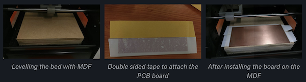
Homing and levelling done, we started testing the milling process with the test board. We followed the instructions and tutorials, converted the png into the MODS and converted it into a millable file.
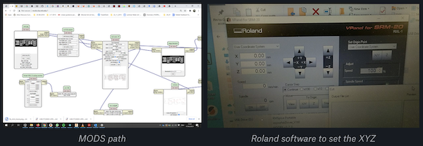
We carefully loaded the 0.3mm end mill in the machine, set the XY axes and the Z. All set and ready to go, we pressed go.
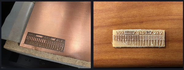
But this didn’t go too well… All tests failed. We broke 5 milling ends and it’s stil unclear what is going wrong. We adjusted the feedrate to 50% in Vpanel, and it happened again… The end mill broke again as soon as it touched the board… Desperate to have some result, we ended up doing the test board with a broken mill. (Which was still 3.5mm at the tip.)
Of course this didn’t give us a satisfying result, but at least we had something.
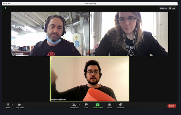
On Friday Kurt and I had a long remote troubleshooting session with Eduardo running us through the whole process again. But he couldn’t see the issue either, so we decided to contact the firm to check whether we might have a set of bad end mills. These troubleshooting sessions are very interesting as remotes, because we do all the lab time by ourselves. Eduardo’s super enthusiastic mood always helps 😄
Of course we wanted to present something, so on Monday we did another test with a 0.2mm V-point end mill. Giving us a much cleaner result! Pfew! We know we have to sort this out, but at least we have a good test plate and a PCB to solder.
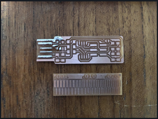
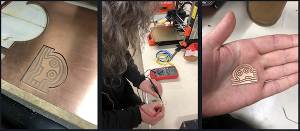
But, as I’m only in the lab one day a week because of covid-19 and homework, I needed to have something on Thursday. An AH-moment to make me excited about the rest of the week. As a maker, I was curious to see what else we could do with a broken end mill. So I loaded up my own design for the small board.
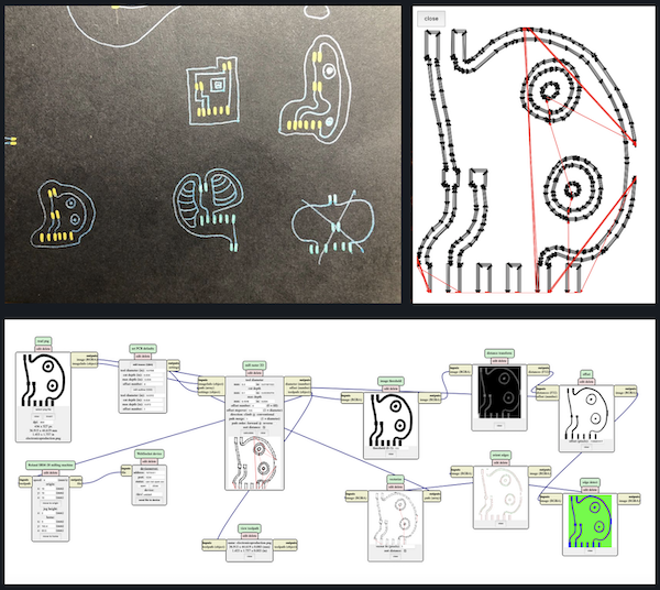
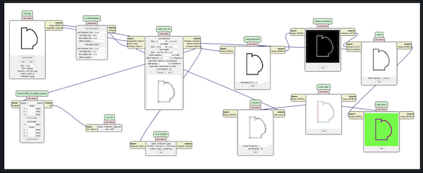
During Neil’s class I drew a couple of possible designs on a piece of paper, taking myself through the process of how components are connected and seeing possible layouts. The next step involved tracing these drawings in Illustrator, I decided to go with the small monster. This was exported into a png and converted into a millable file via MODS.
This went better than the first test piece, but not perfect. It relieved a lot of extra information on how to save files to be able to use them properly and get them in the right size.
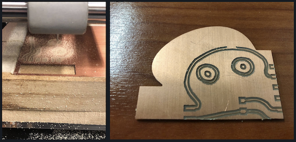
Prepping the files took some careful measuring in Illustrator with the artboards, but once we got that sorted, I ended up with a pretty cool board!
The soldering and programming will have to wait until I can be in the lab again on Thursday to finish the PCB. But in the meantime I’m doing tests with the vinyl cutter and copper foil. Not quite there yet, but that’s a matter of adjusting and trail and error.
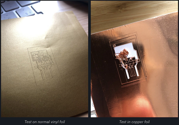
I have yet to continue testing on the foil. But my soldering experience continues.
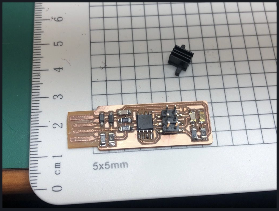
With the programmer milled as it should, it’s time to get soldering. I used Kurt’s programmer as an example.
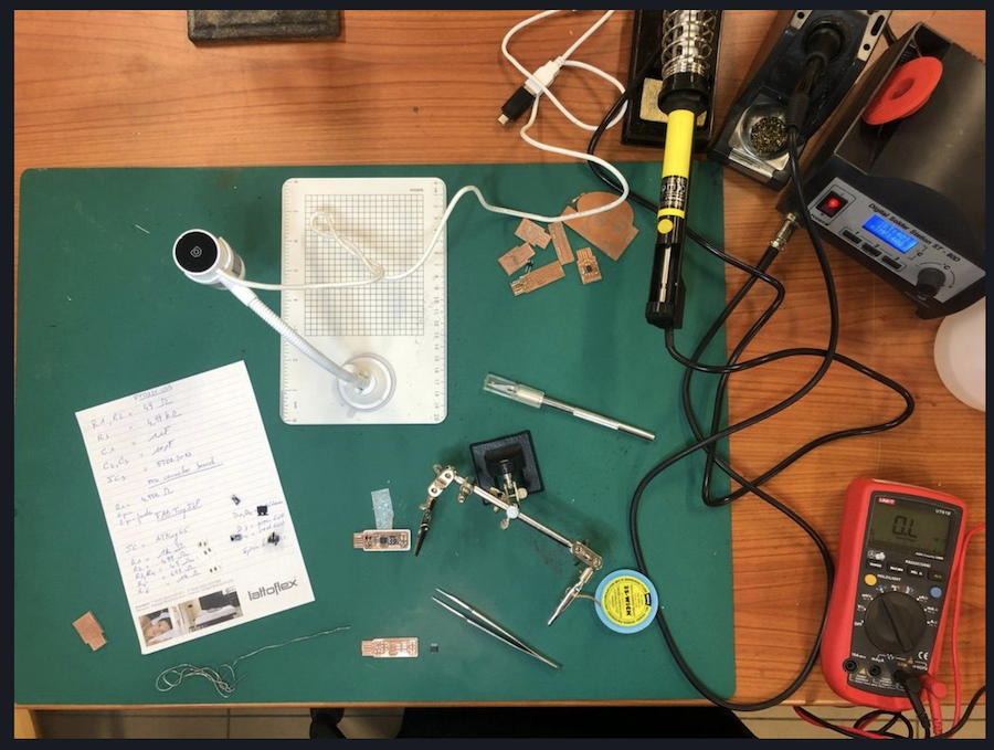
My grandfather learned my to solder when I was 6 years old, but that’s been awhile…. But I’m super happy with the soldering, it came out really nice. Tricky with all the small parts 🙂
Getting the programmer to work has been a hassle to say the least and it took me a long time to find out why it wasn’t working.
Programming the programmer
On mac OS X it takes a few steps.
I followed this tutorial and it took me until Friday afternoon to get the software installed on my macbook. (XCode, Crosspack and Make).
In the end I found out that it’s a lot easier and quicker to use homebrew. Installing homebrew on mac is easy peasy: open terminal and type:
/bin/bash -c "$(curl -fsSL https://raw.githubusercontent.com/Homebrew/install/HEAD/install.sh)"
Installation should start and guide you through the steps.
Add Xcode to homebrew using this tutorial
Install avr-gcc toolchain using:
brew tap osx-cross/avr
and install the latest version of the avr-libc
Other issue: my macbook only has USB-C ports which tend to not work to programme these kinds of chips. With a bunch of dongles and extra cables, it was time to get started. I have use the old school converter, because laptops don’t have a serial port anymore. But my new laptop only has USB-C ports, so i also have to use a Usb-C to A dongle.
Editing the makefile to fit my setup, but everything went wrong. I tried a gazillion times in terminal, but I ended up having error after error after error… Even when trying to write the make command myself in terminal.
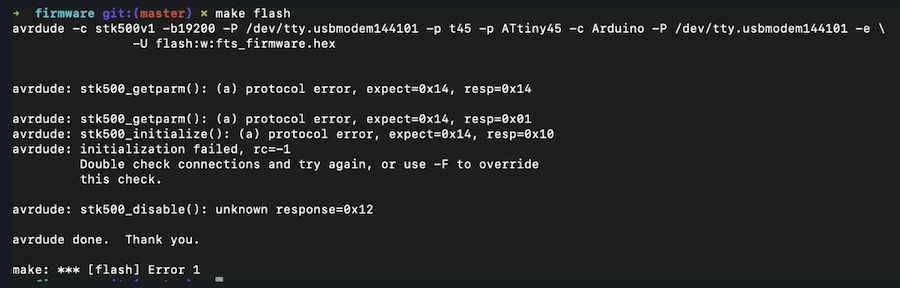
It this point I started to get frustrated, which is never a good thing.
Time to try with the arduino (acting as an ISP, cables ready to go and my old school robot USB-hub as a mediator between the USB-c and USB I’m all set.
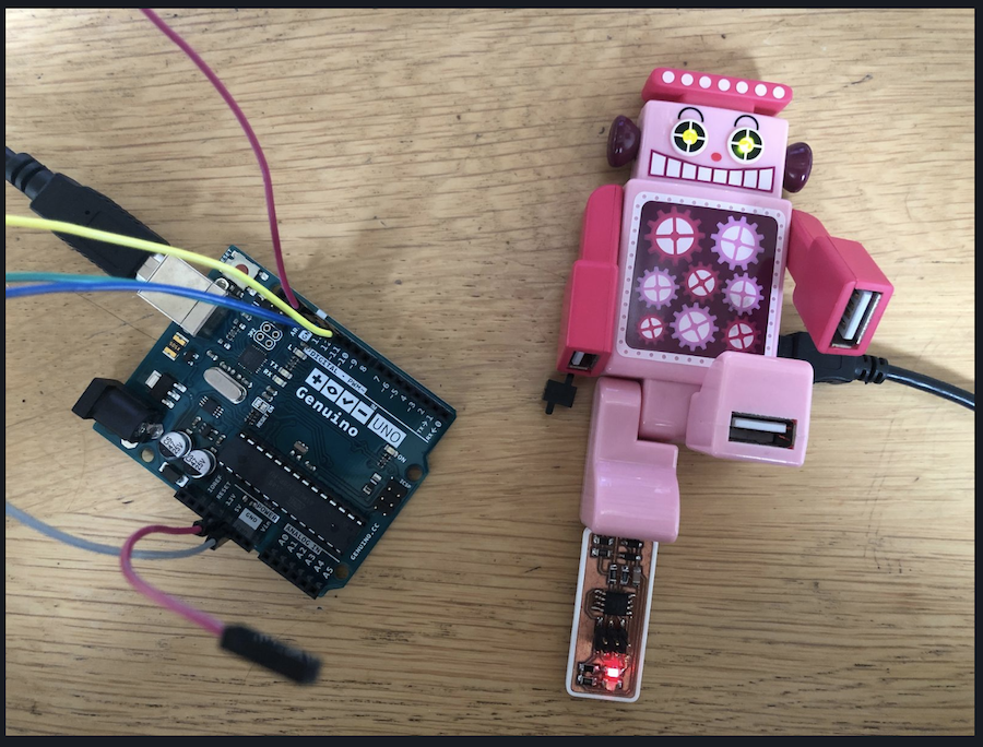
Using the Arduino as ISP allowed me to burn a bootloader on the ATTiny45 and progamme it to blink using the LED script.
But when trying the progamme the chip as a programmer, the fuses still wouldn’t burn…
During our weekly follow-ups with Edu, we talked a lot about the programmers and the problems that could arise, the main things being:
- the cables
- the connectors
- the usb-c ports
Different cables didn’t do the trick, rechecking the connections over and over didn’t do the trick either.
In the end I tried to programme the board using Kurt’s old AVR programmer. That worked, thankfully as I was ready to give up completely.
The steps:
- prepare the makefile
-
use the following command lines in terminal in the folder that contains your makefile
make clean //cleans up what was already in your folder
make flash //this makes the actual hex file and uploads it to your device. It also erases what was in there
make fuses //set up all of the fuses except the one that disables the reset pin
After completing these stepts, check in your system settings of your computer whether the programmer is being recognised by your computer.
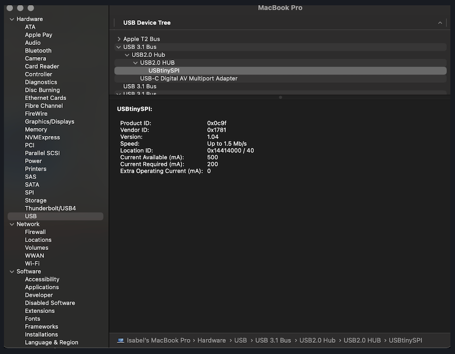
If so, blow the fuses using:
make rstdisbl //blow the rest fuse, now you can't go back
Once they have been blown, desolder the jumper you made between the VCC and the VPROG.
Let’s get programming!