9. Embedded programming
For the group assignment we decided to compare several kinds of microcontrollers. We decided to take the SAMD11C, the arduino ATmega368 and the rasberry Pi. Here is the comparison table of these components.
| Configuration Summary | SAMD11C-14 pin SOIC | Arduino Uno - ATmega328P | Rasberry Pi 3 - Broadcom BCM2837 |
|---|---|---|---|
| Number of pins | 14 | 28 | 40 |
| Number of I/O pins | 12 | 14 Digital I/O Pins; 6 PWM Digital I/O Pins; 6 Analog Input Pins | 40 |
| Flash memory | 16 KB | 32 KB where 0.5 KB are taken by the bootloader | 1GB |
| SRAM | 4 KB | 2 KB | N/A |
| Clock Speed | 16 MHz | 900 MHz * 4 Cores | |
| Time counter (TC) | 2 | N/A | |
| Output channels for TC | 2 | 40 | |
| Timer Counter for Control (TCC) | 1 | N/A | |
| Output channels per TCC | 8 | N/A | |
| Direct memory access channels | 6 | N/A | |
| USB interface | Yes | YES | |
| Serial Communication Interface (SERCOM) | 2 | 2 | |
| Analog-to-Digital Converter (ADC) channels | 5 | N/A | |
| Analog Comparators (AC) | 2 | N/A | |
| Digital-to-Analog Converter (DAC) channels | 1 | N/A | |
| Real-Time Counter (RTC) | Yes | YES | |
| RTC Alarms | 1 | 1 | |
| RTC compare values | 1 32-bit value or 2 16-bit values | N/A | |
| External Interrut Lines | 8 | N/A | |
| Peripheral Touch Controller (PTC) channels for mutual capacitance | 12 (4x3) | N/A | |
| Peripheral Touch Controller (PTC) channels for self capacitance | 7 | N/A | |
| Maximum CPU frequency | 48MHz | 1.2 GHz *4 Cores | |
| Packages | SOIC | 28P3 | Board SoC |
| Oscillators | 32.768kHz crystal oscillator (XOSC32K) 0.4-32MHz crystal oscillator (XOSC) 32.768kHzinternal oscillator (OSC32K)32kHz ultra-low-power internal oscillator (OSCULP32K) 8MHz high-accuracy internal oscillator (OSC8M) 48MHz Digital Frequency Locked Loop (DFLL48M) 96MHz Fractional Digital Phased Locked Loop (FDPLL96M) | N/A | |
| Event System channels | 6 | N/A | |
| SW Debug Interface | Yes | N/A | |
| Watchdog Timer (WDT) | Yes | N/A | |
| Temperature range | -40 to 85°C | -40°C to 85°C | -40 to 85 C |
| Operating voltage | 1,62 to 3,63 V | 1.8 to 5.5 V | 5.1 V |
| Processor | ARM Cortex-M0+ CPU running at up to 48MHz | BCM2837 Broadcom system on chip |
Raspberry Pi 4 specifications table:
| GPIO | Pull | ALT0 | ALT1 | ALT2 | ALT3 | ALT4 | ALT5 |
|---|---|---|---|---|---|---|---|
| 0 | HIGH | SDA0 | SA5 | PCLK | SPI3_CE0_N | TXD2 | SDA6 |
| 1 | HIGH | SCL0 | SA4 | DE | SPI3_MISO | RXD2 | SCL6 |
| 2 | HIGH | SDA1 | SA3 | LCD_VSYNC | SPI3_MOSI | CTS2 | SDA3 |
| 3 | HIGH | SCL1 | SA2 | LCD_HSYNC | SPI3_SCLK | RTS2 | SCL3 |
| 4 | HIGH | GPCLK0 | SA1 | DPI_D0 | SPI4_CE0_N | TXD3 | SDA3 |
| 5 | HIGH | GPCLK1 | SA0 | DPI_D1 | SPI4_MISO | RXD3 | SCL3 |
| 6 | HIGH | GPCLK2 | SOE_N | DPI_D2 | SPI4_MOSI | CTS3 | SDA4 |
| 7 | HIGH | SDA0 | SA5 | PCLK | SPI4_CE0_N | RTS3 | SCL4 |
| 8 | HIGH | SDA0 | SA5 | PCLK | SPI3_CE0_N | TXD2 | SDA4 |
| 9 | LOW | SPIO_MISO | SD1 | DPI_D5 | - | RXD4 | SCL4 |
| 10 | LOW | SDA0 | SA5 | PCLK | SPI3_CE0_N | TXD2 | SDA6 |
| 11 | LOW | SDA0 | SA5 | PCLK | SPI3_CE0_N | TXD2 | SDA6 |
| 12 | LOW | SDA0 | SA5 | PCLK | SPI3_CE0_N | TXD2 | SDA6 |
| 13 | LOW | SDA0 | SA5 | PCLK | SPI3_CE0_N | TXD2 | SDA6 |
| 14 | LOW | SDA0 | SA5 | PCLK | SPI3_CE0_N | TXD2 | SDA6 |
| 15 | LOW | SDA0 | SA5 | PCLK | SPI3_CE0_N | TXD2 | SDA6 |
| 16 | LOW | SDA0 | SA5 | PCLK | SPI3_CE0_N | TXD2 | SDA6 |
| 17 | LOW | SDA0 | SA5 | PCLK | SPI3_CE0_N | TXD2 | SDA6 |
| 18 | LOW | SDA0 | SA5 | PCLK | SPI3_CE0_N | TXD2 | SDA6 |
| 19 | LOW | SDA0 | SA5 | PCLK | SPI3_CE0_N | TXD2 | SDA6 |
| 20 | LOW | SDA0 | SA5 | PCLK | SPI3_CE0_N | TXD2 | SDA6 |
| 21 | LOW | SDA0 | SA5 | PCLK | SPI3_CE0_N | TXD2 | SDA6 |
| 22 | LOW | SDA0 | SA5 | PCLK | SPI3_CE0_N | TXD2 | SDA6 |
| 23 | LOW | SDA0 | SA5 | PCLK | SPI3_CE0_N | TXD2 | SDA6 |
| 24 | LOW | SDA0 | SA5 | PCLK | SPI3_CE0_N | TXD2 | SDA6 |
| 25 | LOW | SDA0 | SA5 | PCLK | SPI3_CE0_N | TXD2 | SDA6 |
| 26 | LOW | SDA0 | SA5 | PCLK | SPI3_CE0_N | TXD2 | SDA6 |
| 27 | LOW | SDA0 | SA5 | PCLK | SPI3_CE0_N | TXD2 | SDA6 |
Programming of SAMD11C - Code
For this week I programmed my board with LEDs and a button. First to learn how to program, I learnt on an Arduino board, with Serial monitor, to learn how to make function, and fill the paragraph on Arduino software. The programmation of this microcontroller is the first microcontroller programmed for the group assignment.
I will put the files of the most advanced programmed I made, because some codes I worte are the step by step I learnt how to code but doesn’t really do much things.
Here is the kind of basic code I wrote.
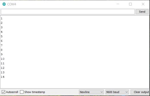
I wrote a code to have a counter print on a serial monitor, to try the tool offer by Arduino. Here I just learnt how to fill the setup and the loop function.
void setup (){
  // put your setup code here, to run once:
  Serial.begin(9600); //speed of communication, 9600 baud, mandatory for the serial monitor to work
  delay(1000); //wait a bit at the beginning
  Serial.printIn("start"); //check if the serial monitor is working
}

int toto = 0; //the counter, an integer

void loop(){
  // put your main code here, to run repeatedly:
  delay(1000); //wait 1 sec, to repeat the loop after
  Serial.printIn(toto); //print the coundter
  toto = toto + 1; //every 1 second, the counter is added of 1
}
This is a screenshot of the serial monitor, where the number of the counter is print.
Arduino website has all the references, function we can use to programm.
During the learning of how to code, I make a mistake in my code. I declared a variable 2 times in the code.
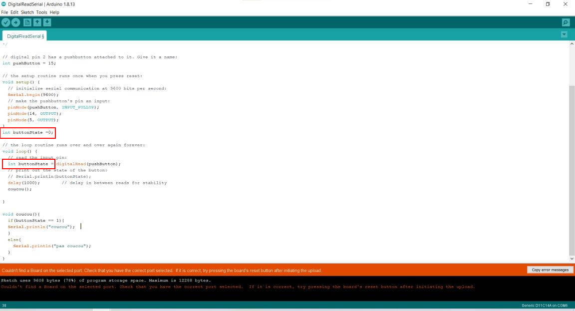
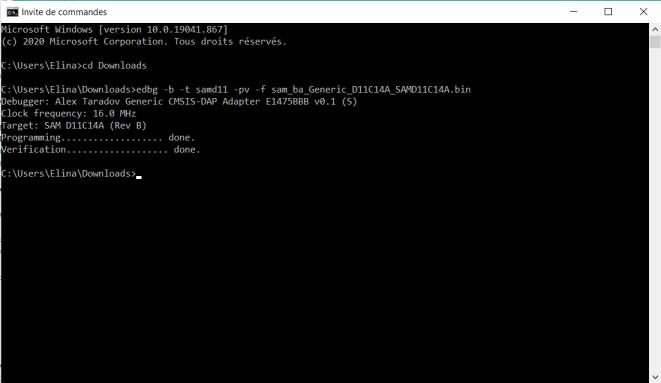
And when I upload the code, it broked the board. I wasn’t able to connect the board to my computer. So I had to reflashed it with the bootloader and the programmer.
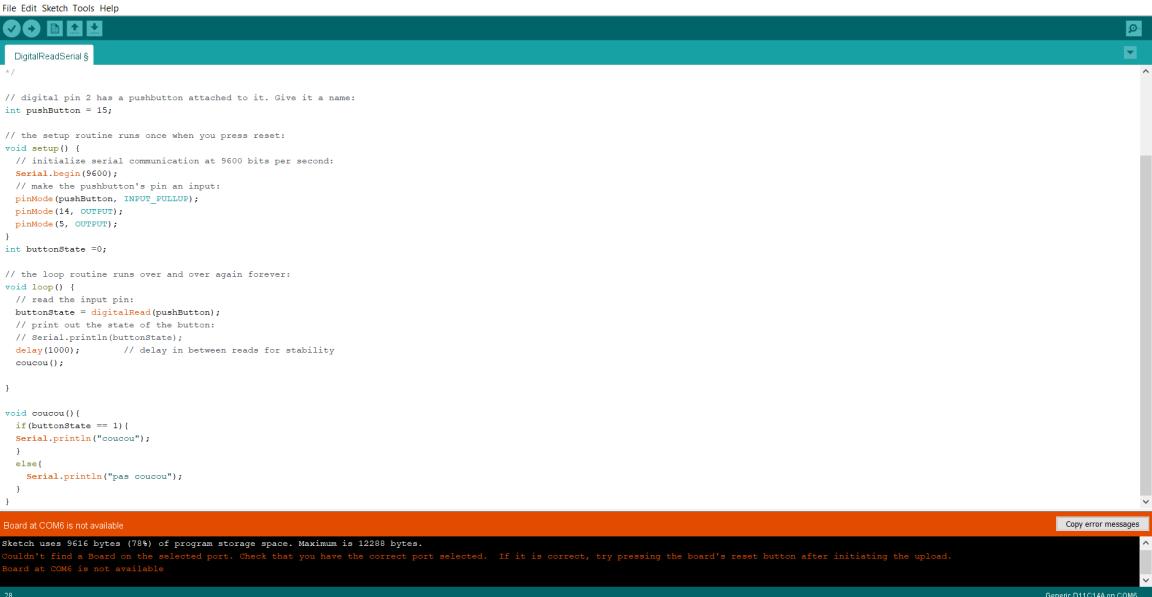
So now, this is the code I wrote to make the green LED on when I push the button, and switch on the red LED when the button is not pushed. I found the number of the pin on the datasheet, mixed with a picture for the name to put on the code, bellow on this website it is explained.
Don’t forget to open the serial monitor at the beginning.
Here I wrote the code in C++ language, using different functions and variables.
int toto = 0; //a integer variable, a counter
int totoref = 0; // a variable that will help to storage the value of my counter and after do comparison
int pinLEDvert = 14; //LED green linked to the pin 14
int pinLEDrouge = 5; //LED red linked to pin 5

int pushButton = 15; //button linked in pin 15

void setup(){
  Serial.begin(9600); //the initial beginning for the serial monitor to be able to work.
  pinMode(pushButton, INPUT_PULLUP); //setup the button
  pinMode(pinLEDvert, OUTPUT); //setup the LED
  digitalWrite(pinLEDvert, HIGH); //check if the LED is working and if we go well in the function
  delay(1000); //wait 1 sec
  digitalWrite(pinLEDvert, LOW); //switch off the LED
  pinMode(pinLEDrouge, OUTPUT); //setup the red LED, and do the same as the LED before
  digitalWrite(pinLEDrouge, HIGH);
  delay(1000);
  digitalWrite(pinLEDrouge, LOW);
}

bool greenLEDstatus = false; //create a boolean

void loop(){
  int buttonState = digitalRead(pushButton); //a variable that will have the state of the button, and help to do some checking in a if loop
  delay(300);
  if(buttonState == 0){ //if the button is pushed, then toto will change, 1 will be added on the variable integer
    toto = toto+1;
  }
  if(totoref != toto){ //if the reference of toto is different of toto, means taht the button has been pushed, the green LED will be on
    Serial.println(toto); //a check if toto has been changed, on the serial monitor
    setLEDvert(true); // check the function below, turn on the green LED
    greenLEDstatus = true;
    setLEDrouge(false); //turn off the red LED
    totoref = toto; //equalize the two variable, to go out from the if
    delay(300);
  }
  else{ //else turn off the green LED, and turn on the red LED, the button has not been pushed
  setLEDvert(false);
  greenLEDstatus = false;
  setLEDrouge(true);
  }
}

void setLEDrouge(bool on_offr){ //same as the next function but for the red LED
  if (on_offr == 1){
    digitalWrite(pinLEDrouge, HIGH);
    //Serial.print("LED rouge ");
    //Serial.println(on_offr);
  }
  else{
    digitalWrite(pinLEDrouge, LOW);
  }

}

void setLEDvert(bool on_offv){ //a function that will turn on or off the LED
  if (on_offv == 1){ //if the boolean is true then the LED will turn on otherwise it will turn off the green LED
    digitalWrite(pinLEDvert, HIGH);
  //Serial.print("LED vert ");
  //Serial.println(on_offv);
  }
  else{
    digitalWrite(pinLEDvert, LOW);
  }

}
The file is available at the end of the page, in all the files.
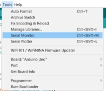
To upload the code on the board with Arduino, first I selected the right board, and not forget to select the port where the Mattairtech board is plugged. And it is the LEDs turned on and off according to the push button.
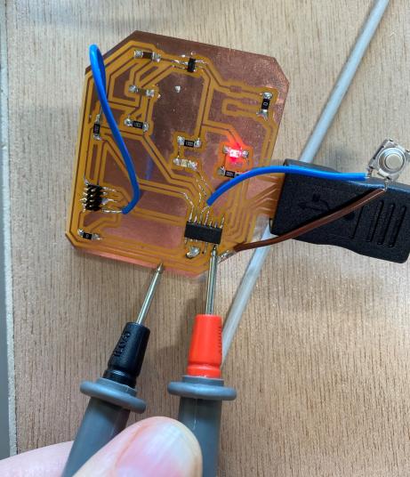
Now because I had issues on one pin on one of my board, I fixed it this week. I change with a wire where the LED is linked on the microcontroller. To check which pin is working, I upload this code in the board, and checked how many volts going out the pin I programmed with the multimeter. I took the basic example on Arduino software and just changed some part to be able to change the number pf the pin quickly.
I won’t put the file of this code, it was taken in the example folder of Arduino, a basic blink, I just added 2 variables to be able to do my checks quickly.
int pinLEDvert = 4; //create a varible of which pin is linked to the LED, to change it quickly and make a test on each pin of the board
int pinLEDrouge = 5; // the red LED is working, and linked to the pin 5

void setup() {
  // put your setup code here, to run once:
  pinMode(pinLEDvert, OUTPUT);
  pinMode(pinLEDrouge, OUTPUT);
}

void loop() {
  // put your main code here, to run repeatedly:
  digitalWrite(pinLEDvert, HIGH); //turn on both LED
  digitalWrite(pinLEDrouge, HIGH);
  delay(1000);
  digitalWrite(pinLEDvert, LOW); //turn off both LED
  digitalWrite(pinLEDrouge, LOW);
  delay(1000);
}
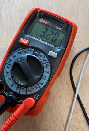
It shows around 3.3 V on the multimeter so I supposed that the pin is working.
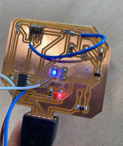
I soldered a wire, and cut the trace where the LED is linked with the microcontroller, and when I plugged the board the LED were blinking both, so it worked.
Micro:bit - programming microcontroller Nordic nRF51822
During the bootcamp week, I discovered a little bit about micro:bit, that’s why I reused this board for this week. On micro:bit website, there is an interface, makecode editor to play with code as blocks. I made the programm with blockly language, that bring to a JavaScript code. The micro:bit board is processed by a MCU Nordic nRF51822.
The programmation of this microcontroller is the second microcontroller programmed for the group assignment.
To test the editor, I put the blocks to make the board print “hello” at the end and when we push the A button, it make a heart shape blink two times. The button B clear the LEDs.
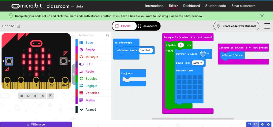
We can also check the code in JavaScript:
input.onButtonPressed(Button.A, function () {
    for (let index = 0; index < 2; index++) {
        basic.showIcon(IconNames.Heart)
        basic.pause(1000)
        basic.showLeds(`
            . . . . .
            . . . . .
            . . . . .
            . . . . .
            . . . . .
            `)
    }
})
input.onButtonPressed(Button.B, function () {
    basic.clearScreen()
})
basic.showString("Hello!")
basic.forever(function () {

})
I did not write the code in JavaScript, but I just checked to know what is going on in with this language and blockly I used.
When the code is done, I just need to download the file and then copy it in the micro:bit board, plugged to my computer.
And here is the result:
This way of working is nice to learn quickly some code, and very nice to see, but it is pretty limited, to the micro:bit board.
ESP32
Théo test also the ESP32. Here is his work
During the Interface and application programming week I also programmed an ESP32. This microcontroller is different from the others already mentioned. Here are the different steps to program with an ESP32 on the Arduino software on a Mac.
The ESP 32 in a few words
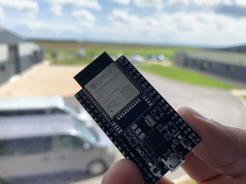
ESP32 is a series of microcontrollers from Espressif Systeme with integrated support for Wi-Fi and Bluetooth (up to LE 5.0 and 5.11). It is an evolution of the ESP8266.
ESP32 is capable of functioning reliably in industrial environments, with an operating temperature ranging from –40°C to +125°C. Powered by advanced calibration circuitries, ESP32 can dynamically remove external circuit imperfections and adapt to changes in external conditions.
ESP32 is highly-integrated with in-built antenna switches, power amplifier, low-noise receive amplifier, filters, and power management modules. ESP32 adds priceless functionality and versatility to your applications with minimal Printed Circuit Board (PCB) requirements.
ESP32 can perform as a complete standalone system or as a slave device to a host MCU, reducing communication stack overhead on the main application processor. ESP32 can interface with other systems to provide Wi-Fi and Bluetooth functionality through its SPI / SDIO or I2C / UART interfaces.
Engineered for mobile devices, wearable electronics and IoT applications, ESP32 achieves ultra-low power consumption with a combination of several types of proprietary software. ESP32 also includes state-of-the-art features, such as fine-grained clock gating, various power modes and dynamic power scaling.
Credit : Espressif Systeme
Installing the ESP32 on the Arduino IDE
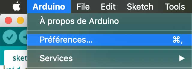
To use the ESP32 with the Arduino software it is necessary to add the board to the software. All the steps are done on a Mac, there may be some inconsistencies with another operating system.
To do this, open the Arduino application and go to Arduino > Preferences then paste this link into this location:
https://dl.espressif.com/dl/package_esp32_index.json
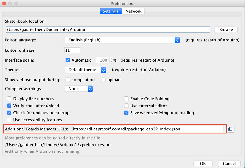
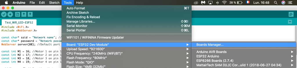
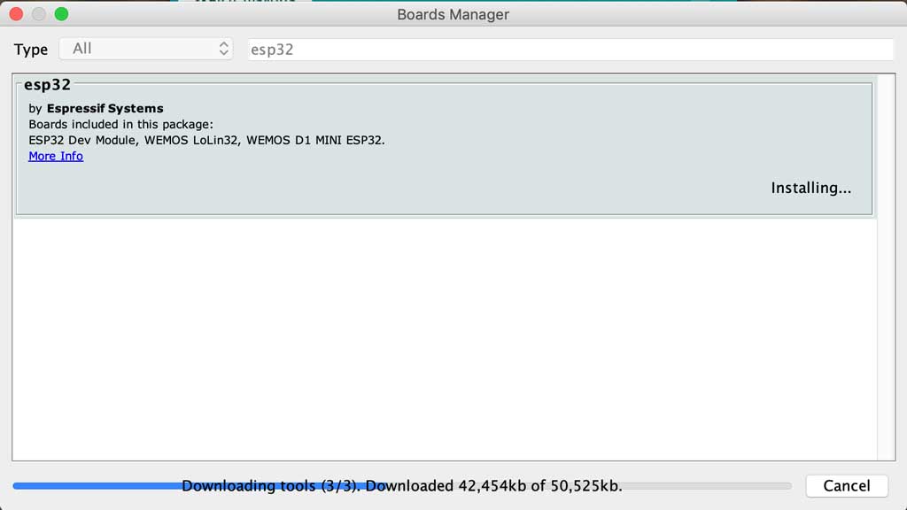
Once you have registered this new link you should also download the boards. To do this you need to open the tools tab > board manager. Type ESP32 in the search bar and download the pack
Installing the CP210x Driver
In order to interface with an ESP32 it is necessary to install a driver to make the link between UART and USB. To do this you need to go to this link and download the appropriate driver for your computer.
https://www.silabs.com/developers/usb-to-uart-bridge-vcp-drivers
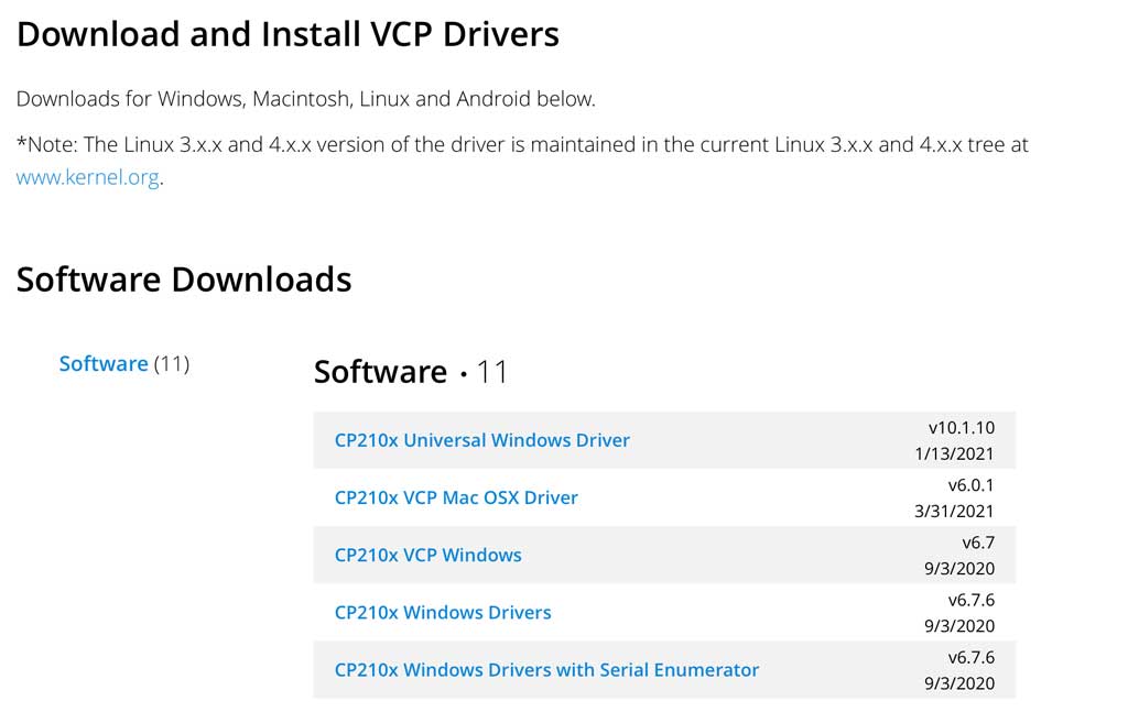
When you have downloaded the file you just have to execute it and then your computer has to restart once the driver is installed.
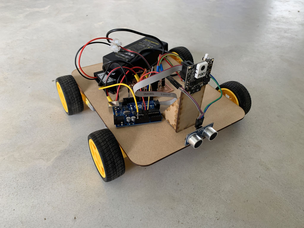
The installation
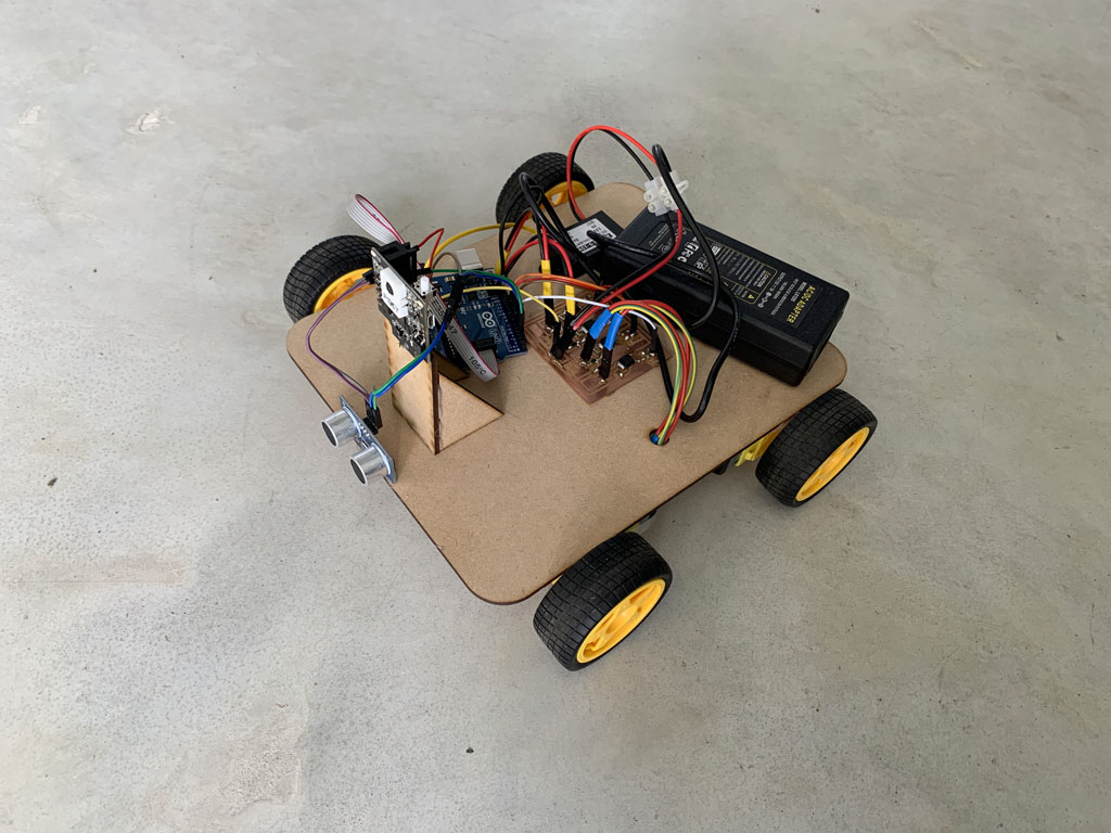
The goal of the week was to control my little robot with a wireless “remote control”.
For more information click here
Creation of the web page
As previously mentioned I would like to control my wireless robot with a wifi connection. For that I need a web interface that would allow me to control my robot remotely. I followed the tutorials of Tommy des rochers (https://tommydesrochers.com) for how to create an HTML interface compatible with an ESP 32.
In this video he explains very quickly and simply how to create an HTML page (it’s in French). To create a rather nice environment he uses the website W3school.com. This site creates templates, so it is very fast to create an interface with a correct style simply and free. After saving the link in your text file, you can call up the templates already created for you.
Here is the code to recreate a page similar to mine. You can change the styles very easily by going to the W3school website and change the references so that your site corresponds to your expectations.
<!SERVER HTML>
<html lang='fr'>
<head>
<title>Server ESP32</title> //Title that your page will have on your browser's tab
<meta http-equiv='refresh' content='60' name='viewport' content='width=device-width, initial-scale=1' charset='UTF-8' /> // Instruction line for updating your page
<link rel='stylesheet' href='https://www.w3schools.com/w3css/4/w3.css'> // Line to link the W3school templates to your page
</head>
<body>
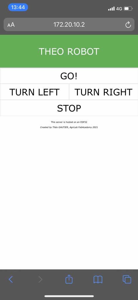
<div class='w3-card w3-green w3-padding-small w3-jumbo w3-center'> // Line that indicates that the background of your title will be green, with a Jumbo text in the middle
<p> THEO ROBOT :</p> // Title on the page
</div>
<div class='w3-bar'> // This sets the following objects to be in a horizontal line
<a href='/go' class='w3-bar-item w3-button w3-border w3-jumbo' style='width:100%; height:50%;'>GO!</a> // This line means that you have a button with an outline, with "GO" written in the centre in jumbo type. Also when selected it will send to the /go page. It uses all the horizontal space on the line
<a href='/left' class='w3-bar-item w3-button w3-border w3-jumbo' style='width:50%; height:25%;'>TURN LEFT</a> // This line means that you have a button with an outline, with "TURN LEFT" written in the centre in jumbo type. Also when selected it will send to the /left page. It uses half of the horizontal space on the line
<a href='/right' class='w3-bar-item w3-button w3-border w3-jumbo' style='width:50%; height:25%;'>TURN RIGHT</a> // This line means that you have a button with an outline, with "TURN RIGHT" written in the centre in jumbo type. Also when selected it will send to the /right page. It uses half of the horizontal space on the line
<a href='/stop' class='w3-bar-item w3-button w3-border w3-jumbo' style='width:100%; height:50%;'>STOP!</a> // This line means that you have a button with an outline, with "STOP" written in the centre in jumbo type. Also when selected it will send to the /stop page. It uses all the horizontal space on the line
</div>
<div class='w3-center w3-padding-16'> // This means that the text that follows will be centred and sparsely spaced.
<p>This server is hosted on an ESP32</p> // Normal text
<i>Created by Théo GAUTIER, AgriLab FabAcademy 2021 </i> // Text written in italics
</div>
</body>
<html>
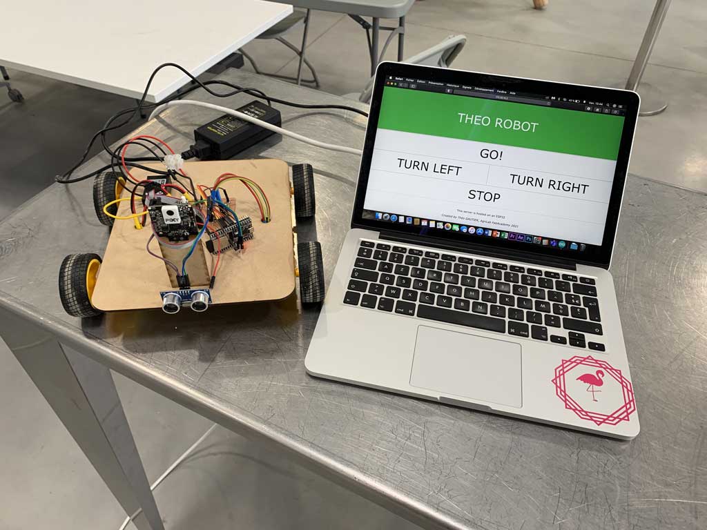
This interface has the advantage of working equally well on computer, tablet or smartphone
The code in C++
Now that our web page is functional, we need to insert it into the C++ code to be used by the ESP32. The code being in HTML and the instructions in Arduino in C++ we have to find a way for the server to be read by the microcontroller. To do this, the technique used by Tommy des Rochers is to use the String function. By doing this, the ESP32 can host the server locally and can therefore interact with a web page.
#include <WiFi.h>
#include <WebServer.h>

const char* ssid = "Network name"; // Network name
const char* password = "Network password"; // Network password
WebServer server(80); //Default port for the ESP32 server relationship

const int M1 = 16; //Motor 1 on pin 16
const int M2 = 17; //Motor 2 on pin 17
const int M3 = 18; //Motor 3 on pin 18
const int M4 = 19; //Motor 4 on pin 19

void Homepage() // Function that contains my server and serves as my homepage
{
  String page = "<!SERVER html>"; // The lines in my HTML server preceded by the string function so that it is readable by the ESP32

    page += "<html lang='fr'>";

    page += "<head>";
    page += "    <title>Server ESP32</title>";
    page += "    <meta http-equiv='refresh' content='60' name='viewport' content='width=device-width, initial-scale=1' charset='UTF-8' />";
    page += "    <link rel='stylesheet' href='https://www.w3schools.com/w3css/4/w3.css'>";
    page += "</head>";

    page += "<body>";
    page += "    <div class='w3-card w3-green w3-padding-small w3-jumbo w3-center'>";
    page += "    <p>THEO ROBOT </p>";
    page += "    </div>";

    page += "    <div class='w3-bar'>";
    page += "        <a href='/go' class='w3-bar-item w3-button w3-border w3-jumbo' style='width:100%; height:50%;'>GO!</a>";
    page += "        <a href='/left' class='w3-bar-item w3-button w3-border w3-jumbo' style='width:50%; height:50%;'>TURN LEFT</a>";
    page += "        <a href='/right' class='w3-bar-item w3-button w3-border w3-jumbo' style='width:50%; height:50%;'>TURN RIGHT</a>";
    page += "        <a href='/stop' class='w3-bar-item w3-button w3-border w3-jumbo' style='width:100%; height:50%;'>STOP</a>";
    page += "    </div>";

    page += "    <div class='w3-center w3-padding-16'>";
    page += "        <p>This server is hosted on an ESP32</p>";
    page += "        <i>Created by Théo GAUTIER, AgriLab FabAcademy 2021</i>";
    page += "    </div>";

    page += "</body>";

    page += "</html>";

    server.setContentLength(page.length()); //This allows the ESP32 to know the length of the website, which allows faster communication
    server.send(200, "text/html", page); // Enables data to be sent
}

void NotFound() // Function that writes to the user "404 Not found" if a page is unknown
{
    server.send(404, "text/plain", "404: Not found");
}

void go() //Function that allows the robot to move forward, all motors are on
{
    digitalWrite(M1, HIGH);
    digitalWrite(M2, HIGH);
    digitalWrite(M3, HIGH);
    digitalWrite(M4, HIGH);
    server.sendHeader("Location","/"); // This then links to the home page
    server.send(303); // Command that tells the server it is doing a redirect
}

void stop() //Function that allows the robot to stop, all motors are off
{
    digitalWrite(M1, LOW);
    digitalWrite(M2, LOW);
    digitalWrite(M3, LOW);
    digitalWrite(M4, LOW);
    server.sendHeader("Location","/"); // This then links to the home page
    server.send(303); // Command that tells the server it is doing a redirect
}

void left() //Function that allows the robot to turn left by stopping motors 1 and 2
{
    digitalWrite(M1, LOW);
    digitalWrite(M2, LOW);
    digitalWrite(M3, HIGH);
    digitalWrite(M4, HIGH);
    server.sendHeader("Location","/"); // This then links to the home page
    server.send(303); // Command that tells the server it is doing a redirect
}

void right() // Function that allows the robot to turn right by stopping motors 3 and 4
{
    digitalWrite(M1, HIGH);
    digitalWrite(M2, HIGH);
    digitalWrite(M3, LOW);
    digitalWrite(M4, LOW);
    server.sendHeader("Location","/"); // This then links to the home page
    server.send(303); // Command that tells the server it is doing a redirect
}

void setup()
{
  Serial.begin(115200);
  delay(1000); // Delay 1s
  Serial.println("\n"); // Make a line break in the serial monitor

  pinMode(M1,OUTPUT); // Says that M1 is an output
  pinMode(M2,OUTPUT); // Says that M2 is an output
  pinMode(M3,OUTPUT); // Says that M3 is an output
  pinMode(M4,OUTPUT); // Says that M4 is an output
  digitalWrite(M1, LOW); // Set M1 to stop
  digitalWrite(M2, LOW); // Set M2 to stop
  digitalWrite(M3, LOW); // Set M3 to stop
  digitalWrite(M4, LOW); // Set M4 to stop

  WiFi.begin(ssid, password); // Function to start the wifi connection
  Serial.print("Connection in progress..."); // Print on the serial monitor "Connection in progress..."

  while(WiFi.status() != WL_CONNECTED) // As long as the connection to the network has not been established then print a dot every second
  {
    Serial.print(".");
    delay(1000);
  }

  Serial.println("\n");  // Make a line break in the serial monitor
  Serial.println("Connection established!");  // Print on the serial monitor "Connection established!"
  Serial.print("Adresse IP: ");   // Print on the serial monitor "Adresse IP:"
  Serial.println(WiFi.localIP()); // Print on the serial monitor the local IP


  server.on("/", Homepage); // When the server is on "/" then do the homepage function
  server.on("/go", go); // When the server is on "/go" then do the go function
  server.on("/left", left); // When the server is on "/left" then do the left function
  server.on("/right", right); // When the server is on "/right" then do the right function
  server.on("/stop", stop); // When the server is on "/stop" then do the stop function
  server.onNotFound(NotFound); // When the server is not found then do the NotFound function
  server.begin(); // Start the server

  Serial.println("Active web server!"); // Print on the serial monitor "Active web server!"

}

void loop()
{
  server.handleClient(); // Manage the user who is connected to the server
}
For more information click here
The server hosted on the ESP32 allows communication between a web interface and a board. The ESP32 is connected to my own wifi network created by my iPhone. Once on the web page with my Mac or iPhone I can interact with the ESP32 by clicking on the buttons that will then perform the registered functions. This is how I can drive my robot with an ESP32 and a wifi connection.
Video ESP32
- Musique : Patrick Abrial - Misirlou*
- A big thank you to Anthonio for having put his talents as a cameraman to good use, it allowed us to have a spectacular result*