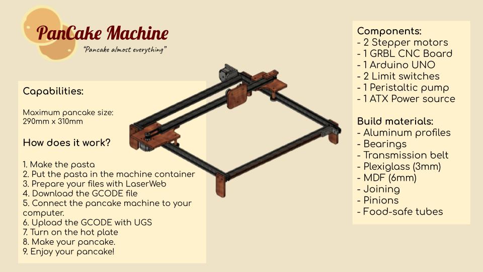
10. Machine week
This week we work as a group with Antonio, Theo and Elina on how to built a machine.
Assignment:
Mechanical design

group assignment
   - design a machine that includes mechanism+actuation+automation
   - build the mechanical parts and operate it manually
   - document the group project and your individual contribution

Machine design

group assignment
   - actuate and automate your machine
   - document the group project and your individual contribution
Slide
Video shot
Credits for Theo for making the video of this week.
Code used for audio/video compression:
ffmpeg -i demo.mp4 -codec:a libmp3lame -b:a 32k -b:v 1400k demo_1400_32.mp4
Day 1 - thinking of an idea, looking for kind of equipment with have at Agrilab, start the design and test some electronics
On the first day, we made a brainstorming together on which kind of machine we want to build and how to build it.

We want to have a device that is working with 2 or 3 axes.
- First Theo has the idea to make a smart garbage sorting device, where we put some garbage in a box and with buttons, it will throw the garbage in the right trash can we would have built.
- The second idea was to make a device that print pancakes to a warming plate, to draw pancakes with different shpaes, such as pancakes in the shape of houses, or animals.

So we decided to make a pancake printer because it is a device that interested us, to make something with food. We started to think to a way to make this device, we drew on paper how the machine could work. We want to have an extruder, to pour the pancake dough on the plate, that will move on 2 axes, X and Y, with motors. We thought about 2 differents systems to pour the pancake dough. Because this paste is pretty fluid, we thought of a system with pump that will bring the dough to the extruder, or a system with a syringe, that can be activate with a motor to push the pancake dough.

Some shields for Arduino have been ordered in our lab for this week so we gonna use an Arduino mega board with a shield GRBL to use gcode to pilot our device.
Antonio talked to us about peristaltic we can use for the device. In Agrilab we have a device that dispense hydroalcoholic gel (because of the pandemic) which is using this kind of pump. We went to check it for how it works and how we can use it in the device.


To move the extruder of pancake dough we have thought of two possibilites:
- One is the plate that can move, like creality 10

- Second is to have 2 axes for the extruder
We would like to use a hotplate that can be find in a kitchen, with a pan, that’s why we are choosing the second possibilities. To do this we drew a ramp system.

Now we have a pretty clear idea in our mind, we went over Agrilab to look of all the device we have and which system inspire us.
We have a 3D printer where we can see the mechanism, a Creality ender 5 plus.

It is working with wheels that roll along an aluminium V-profile rail that is drived with a belt thanks to a motor and a puley for X and Y axes.

One of the axes is drived with a motor with two sides.

For the Z axe, it is the plate that goes up and and down with a threaded rod and a motor.

We found in storage aluminium profiles that we will certainly use.

In Agrilab we have an other device made by Luc, that engrave cardboard plates.

Here is it moving accoding to a motor with puley, a belt and wheels that block everything.

There is this kind of system with motors on both sides of the aluminium V-profile that are coordinate to move together.
The other axis is working according to the same principle.
We took a look on a small CNC built in our lab.

This device is moving with bearings, metal sticks and the movement is make by and threaded rot with a screw, that turn with a motor and drive the cnc tool.

We found in the storage some metal sticks that fit perfectly with the bearing that we have at our disposal, and also threaded shafts with screw, but that is not the system we gonna use.
We were inspired by all these systems to make our pancake printer bot. We were given some wheels for the aluminium V-profiles to check what is it.
Now we have started to design our machine. Theo started the design on Fusion 360.


Fusion 360
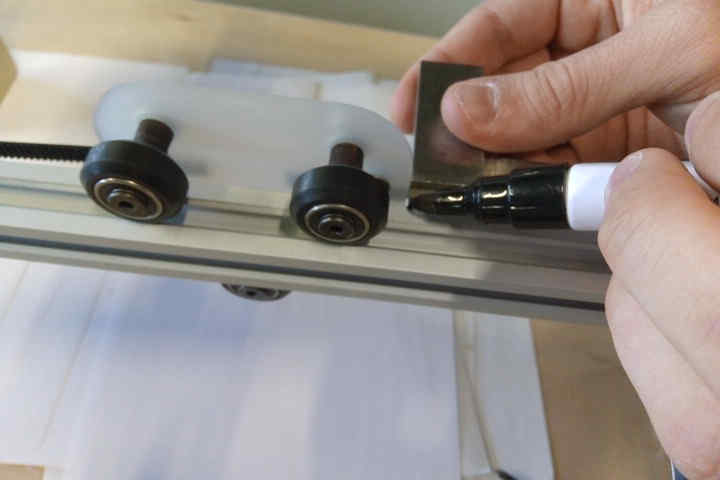
Theo did all the design on Fusion 360. For this I was very inspired by the machines we have at AgriLab. After thinking about it and looking for materials in storage we decided on a machine that moves on 20 x 20 mm aluminium profile rails. In addition to our rails we found bearings and wheels that fit perfectly into our V-profiles. So we were able to make a list of all the items we were going to take.
- Aluminium profile 20 x 20 mm
- Bearings
- 2 Nema17 motors
- Transmission belts
- Output pinions for the motor
- 2 stop switches for our X and Y axes
- 1 power source
- 1 peristaltic pump
- Plexiglass 3mm thick
- 6mm thick MDF
- Nuts, bolts, washers…


So I started the design by adding a Mc MasterCarr component, our profiles. I then extruded it to the length we wanted. In order to make the frame of our machine I moved them (1). Then I made the support for the crossbar (2). This support is held in place by three bearings, inserted with Mc MasterCarr, and then moved on the drawing (3). I then did the same thing on the other side of the machine (4). I added a pivot point for the belt. This point will have a double use, first to send the belt back to the other side but also to tension the belt (5). I have inserted our nema17 engine. For this I had to modify a support bracket to be able to fix the motor. I used the datasheet of the motor to make the fixing holes (6). In the continuity I made the carriage (7). I then made the mounting bracket and inserted the second motor (8). Again with Mc MasterCarr I inserted the drive belts (9). Finally I made the feet of our machine. Here is the finished machine (10).
How do I make a McMaster Carr insertion ?
It’s very simple, just click on the insert button and then click on insert McMaster-Carr component. A dialogue box will open and you will have to find the object you want. In this example I would like to insert a screw. Once you have found the object you want, click on product detail CAD and download the object in 3-D STEP format. Once all these steps have been completed you can move your object wherever you want.

Exporting parts for laser cutting.
In order to cut our parts quickly and precisely we chose to use our laser cutter. To do this I exported all our parts to be machined so that I could save the sketches in DXF. To check if our supports were good we decided to cut our parts on cardboard.

I made some modifications with these cuttings.
- I added an extra bearing on the crossbar support. This support will have 4 bearings instead of 3. This is to increase the precision of the movement.
- I modified one base to be able to integrate the motor directly into the base.
- I modified a foot to be able to force in a bearing for the belt return pinion. The same for the other belt tensioner
- I added the fixing holes for the belts in the supports

With all these modifications I was ready to make the final cuts. For that I exported my sketches in DXF again. For the bases we used 6mm thick MDF. For the rest of the machine we used 3mm thick plexiglass. Plexiglass has the particularity to be food safe. The purpose of our machine being to make edible pancakes it is preferable to look at the materials we use to avoid danger.
Cutting the aluminium profile

The structure of our machine is made of aluminium profile. At AgriLab we have large bars that need to be cut with our band saw. Being a dangerous and complex machine to use, it was a worker from the Lab who cut our profiles.
Assembly

Once all the parts were cut and grouped together I was able to assemble the whole machine. I started by assembling the chassis with brackets. Then I assembled the crossbar and added the bearings. Finally I assembled the legs.
Fitting the motors, belts and limit switches

Once Antonio finished presetting the motors I was able to insert them on the machine. Then to transmit the power of the motors I added two toothed belts. I tightened them on the supports and then finalized their tension by adjusting the tensioners. The goal is to have the belts tight but not too tight. This adjustment is done by the sight and touch of the operator. Finally, I had the task of positioning the machine’s stop switches on the X and Y axes.

Box for the integration of the wires

My last mission for this group work was to make boxes to hide the Arduino, the wires and to fix the peristaltic pump. For that I used the makercase website to make the box. Then I imported the DXF file in fusion to make the fixing holes. I also cut these parts with a laser to have precision and speed of action.


Antonio was looking into a power source for our motors.

And he also tried to flash the Arduino board with the shield for CNC.

Peristaltic pump
I personally worked on the system to make the pump bring the pancake paste to the warming plate. For the machine we built, I worked on the peristaltic pump. First I needed to make the pump turn in one way and an other way to have a retract of the paste of pancake inside the tube. The first step was to find how to plug the pump to an arduino board to flash it.

The pump is made of ball bearings and silicone pipe. It is working with 12V current and 2A. The motor is a DC motor. In AgriLab the instructors ordered for us some H-bridges for the motors. I looked on internet how to wire the motor of the pump with that and on Arduino and I found this website on how to use H-bridge with a L298N motor.
This schematic were very useful to know where to plug what. //schematic
This website helped me also to understand how to control the CNC shield with Arduino.
The pump is powered with an AC/DC electric power supply 12V.

Step by step, I wrote the code to make the pump turn. The program is taking a value written in the serial monitor and send it to the motor as the speed. The turning side of the motor depend on the sign of the number (positives numbers will turn in one directon, negatives numbers will turn in another one).
Here is the wiring of the pump I made:


Here is the code I wrote. I used the IDE Visual Studio Code I discovered during a previous week. First there is the constants, the pins where the wires are plugged. In the setup function, I set the pins as outputs. Then I wrote a function for the movement, with two variables, the speed and the direction. And in the loop I first collect the value of the speed that is set, then transform it a bit in order to make it nice for the motor.

Here 200 is the speed of the motor, -200 is the same speed but in the other side, and -1 stop the motor.
I got a problem on the value when I print it on the serial monitor. The value I wrote is read but after the delay it take again the 0 value, and stop the motor. To fix that the 0 was excluded for the program and I changed the stop for the value -1.
#include <Arduino.h>

//https://ardwinner.jimdofree.com/arduino/iv-les-moteurs-continus/3-faire-tourner-un-moteur-dc-bidirectionnel-avec-un-module-l298n/
//https://arduino.blaisepascal.fr/pont-en-h-l298n/

//declaration des variables et des constantes
int enA = 9; //les pins avec des tilds
int in1 = 10;
int in2 = 11;

int speedmotor = 0; //vitesse du moteur

void setup() {
  // put your setup code here, to run once:
  pinMode(enA, OUTPUT);
  pinMode(in1, OUTPUT);
  pinMode(in2, OUTPUT);
  Serial.begin(9600); //la valeur de communication
}

void move(int speed, bool testforward) {// speed between 0 and 255 analog write, test d'un booléen pour aller dans un sens ou dans un autre
  if (testforward){
    digitalWrite(in1, HIGH); //envoie du courant dans un sens (set to +)
    digitalWrite(in2, LOW); //en envoie pas, le récupère (set to -)
  }
  else{
    digitalWrite(in1, LOW);
    digitalWrite(in2, HIGH);
  }
  analogWrite(enA, speed);
}

void loop() {
  // put your main code here, to run repeatedly:
  if(Serial.available() > 0){ //si la board arduino est branchée
    speedmotor = Serial.parseInt(); // speedmotor recupere la valeur inscrite dans le serial
    Serial.println(speedmotor);
    if (speedmotor == 0){
      return;
    }
    if(speedmotor > 0){ //si speedmoto a une valeur, plus grande que 0
      if (speedmotor > 255){
        speedmotor = 255; //speedmotor est forcé à 255 maxi
      }
      move(speedmotor, true); //alors marche avant
    }
    else if(speedmotor < -1){
      speedmotor = -1*speedmotor; //pour que la vitesse ait une valeur de vitesse mais en marche arrière
      if (speedmotor > 255){ //recopiage du test parce que speedmotor est de nouveau positif
        speedmotor = 255; //speedmotor est forcé à 255 maxi
      }
      move(speedmotor,false); //marche arriere
    }
    else if(speedmotor == -1){ //c'est zero donc tout s'arrete
      digitalWrite(in1, LOW);
      digitalWrite(in2, LOW);
    }
  }
}
With this code, I was able to make the viscosity test of the pancake paste in the tubes.
Viscosity test
I cooked the first pancake paste according to this recipe.
- 150 g of flour T55
- 1 egg
- 1 tablespoon of sugar
- 1 tablespoon of oil
- 1 teaspoon of chemical yeast
- 200 mL of milk
I made a small test with this consistency of dough but it is too liquid, the flow continues to fall even with gravity when the pump is stopped.

So I made different paste with different viscosity, the first one is the control sample, with initial recipe.

The second one has 25% more flour, and the third one has 50% more flour. We can see the different viscosity of the paste on the video.
To make the extruder I assembled some tubes from the largest to the smallest we could find. The biggest one is 7.6 mm, the second is 5.4 mm, the third one is 3.5 mm,a nd the last one is that small iI wasn’t able to measure it with the calliper.

I also tested the different tube with the different viscosity of the paste.
With the pipe of 3.5 mm I draw by hand a line on the warm plate to see how the dough is reacting to warm. We can see that the less viscose paste make the thinner line. After we taste it, because of too much flour we pour inside it is not really tasty.

We finally decided to take the consitency of the second dough, with 25% more flour, and the third pipe.
Improving the control of the pump with a joystick
After making the pump turning according to some values, I wanted to add an input, a joystick to control the speed of the pump. I searched on internet how to use a potential meter and found this very useful website on how to control a potential meter with Arduino. There is a picture of the wiring and how to control a LED with a potential meter.

I apply this to my motor of the pump.
To understand how a potential meter is working I just copied the code and watch the values of the potential meter printed on the serial monitor.

To plug everything on the Arduino board I checked this website with H-bridge and Arduino and I followed this schematic with the potential meter and the motor.

I discover the function map to transform some value to some other which was very usefu because the motor handle values from 0 to 255 and the potential meter have value from 0 to 1023. I modify the code to make the pump go in a way or in an other according to the position of the potential meter.


Here is the code I wrote, and we use it for the device, the pancake bot.
#include <Arduino.h>

//https://ardwinner.jimdofree.com/arduino/iv-les-moteurs-continus/3-faire-tourner-un-moteur-dc-bidirectionnel-avec-un-module-l298n/
//https://arduino.blaisepascal.fr/pont-en-h-l298n/
//https://www.mataucarre.fr/index.php/2019/03/09/utiliser-un-potentiometre-avec-un-arduino/

//declaration des variables et des constantes
int enA = 9; //les pins avec des tilds
int in1 = 10;
int in2 = 11;
int pot; //valeur du potentiometre

int speedmotor = 0; //vitesse du moteur

void setup() {
  // put your setup code here, to run once:
  pinMode(enA, OUTPUT);
  pinMode(in1, OUTPUT);
  pinMode(in2, OUTPUT);
  Serial.begin(9600); //la valeur de communication
}

void move(int speed, bool testforward) {// speed between 0 and 255 analog write, test d'un booléen pour aller dans un sens ou dans un autre
  if (testforward){
    digitalWrite(in1, HIGH); //end current in one side (set to +)
    digitalWrite(in2, LOW); //receive the current (set to -)
  }
  else{
    digitalWrite(in1, LOW);
    digitalWrite(in2, HIGH);
  }
  analogWrite(enA, speed); //send some speed to the motor
}

void loop() {
  // put your main code here, to run repeatedly:
    pot = analogRead(A0); // read the value of the potentialmeter
    delay(200);
    Serial.println(pot); //print the value, to have a check
    if(pot < 470){ //separate the value of the potential meter, and have a gap of 40 to be sure to taje the value
      speedmotor = map(pot, 470, 0, 0, 255); // the speedmotor variable take the value of pot that is transformed, the speed has to be from 0 to 255, map function transform the value, when the potential meter go farther the origin, it increae the peed of the motor
      move(speedmotor, true); //alors marche avant
    }
    else if(pot > 550){ // other case, the potentialmeter is in the other side
      speedmotor = map(pot, 550, 1023, 0, 255); //map the value, but in the other way
      move(speedmotor,false); //marche arriere
    }
    else{ // if it is not on the values before it stops
      digitalWrite(in1, LOW);
      digitalWrite(in2, LOW);
    }
}
To control the peristaltic pump for our pancake bot, we used this system so they are two Arduino boards to control the pancake bot. We decided to use the joystick because the time was short, and we wanted to have the device ready pretty quickly.
When I first tried the code I took a new pump but the ball bearings inside were broken. I first believed that the code I wrote were miswritten, but it finally was the pump that actually don’t work. It took me a little time to figure out that it was the pump and not the code.

Improving the control of the pump with Gcode
I wanted improve the control of the peristaltic pump with the Gcode, to have the control of the pump directly in the code and not manually with the joystick.
First I looked for a way to understand gcode, so I followed a tutorial on how to control a CNC with Arduino and grbl. Here is the tutorial on how to flash arduino with grbl. To use Arduino IDE with grbl I need to install it so according to the tutorial I installed grbl.
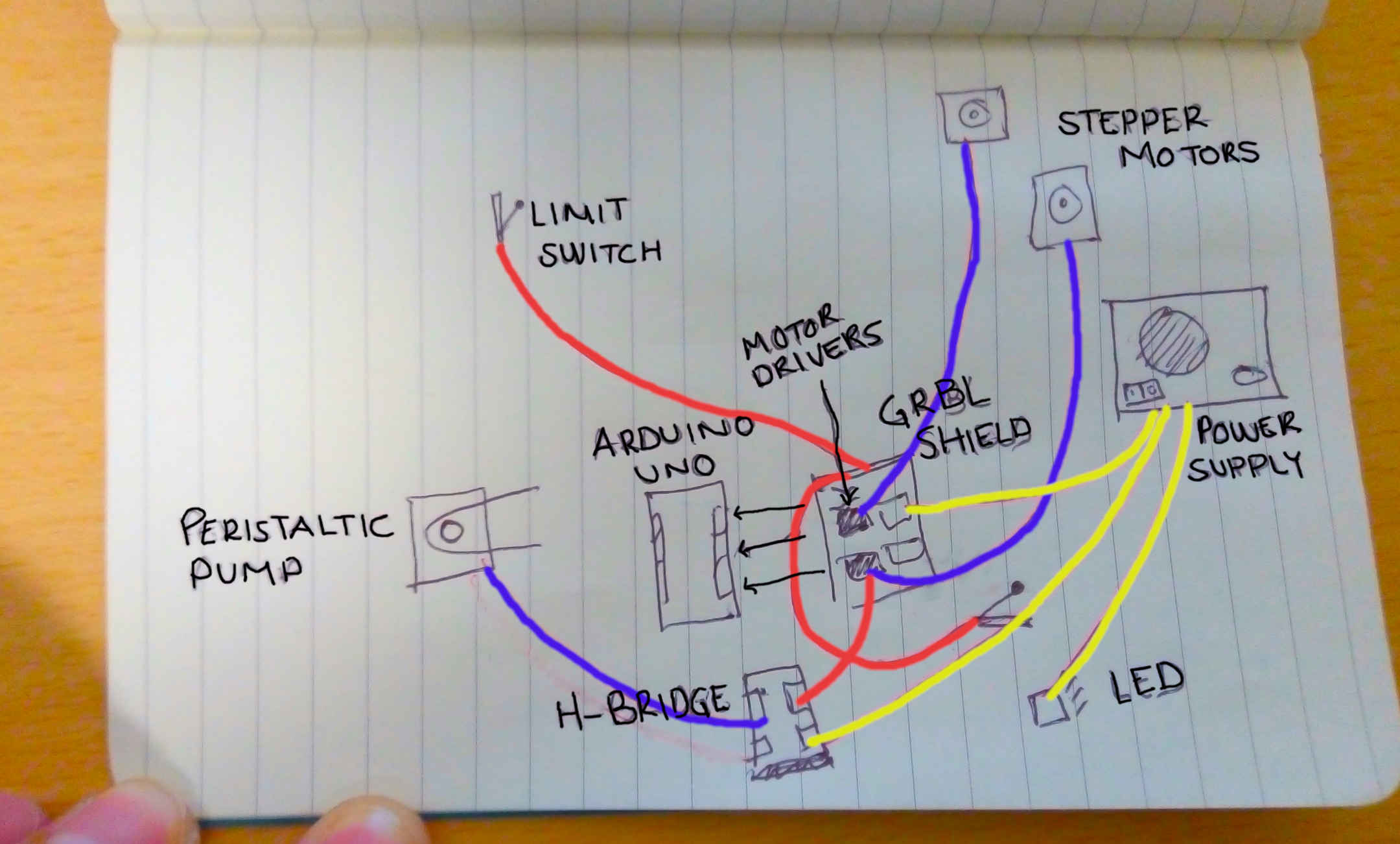
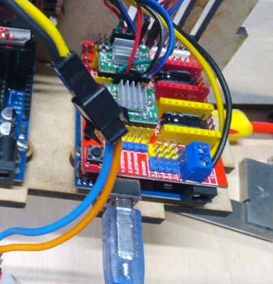
I started by building the electronic system with 2 motors, on for X and one for Y. With the equipment we add and thanks to some pictures on internet I plugged the shiel CNC for Arduino on the Arduino board and try to understand how to plug the motor and the power source on it.

I found on a blog how to use the shield CNC for Aduino. The shield I have is a V3, and thanks to the picture I succeed to plug eveything to the Arduino, and the writing on the shield. To plug the motor on the right side I looked for a datasheet of the motor to know which wire goes to which wire. I found this datasheet but the datas are wrong. My instructor helped to find the good side and replugged everything right. To do that we use Dupont wire. We turn the motor manually while plug to hole together with the wire, and when we feel a strength in the motor it means that the color wires go together.
So the red goes with the green, and the blue with the black. Here is the wiring I made.

I also installed Universal Gcode Sender to control the motor. And according to the tutorial I mainly followed on how to use grbl with Arduino.
I searched to learn more on G.. command in gcode. The Marlin website were really useful to understand more the gcode command. On the terminal of UGS (Universal Gcode Sender), I wrote this line to make the motor work
G21G91G1X5Y5F50
Which means :
- in millimeters
- with relative coordonate
- make a linear move
- in X, 5 mm
- in Y, 5 mm
- with a Feedrate at 50
And here is the video on how the motors are working with this line of code.
Now I understood a little bit more, I wanted to add my pump to the system. I found the Gcode command for the spindle here.
- M03 = CW Spindle
- M04 = CWW Spindle
- M05 = Spindle
I tried to look on internet to know how to plug the H-bridge to the CNC shield, for example on this blog, but after reading what is written on the shield and on the H-bridge I finally plugged together whe pin where the name seems the same and see what it is doing.
ENA with SpnEn, one In with SpnDir, and the In with the ground GND.

Here is the wiring between the H-bridge and the CNC shield for Arduino.


Here is the wiring with the motor of the pump and the H-bridge.

Here is the all wiring between the two motors, the shield for Arduino, the H-bridge, and the peristaltic pump.

Here is the focus on the wiring between the H-bridge for the pump and the shield for Arduino.

I might have plugged the wire in a wrong way because the command line doesn’t really work has they supposed to do but it still work for the device. M03 start the spindle and M04 stop the spindle. It is maybe because the current flow only in one way, that why the reverse wpindle stop the spindle actually.
Here is the video of the pump controlled by gcode.
GRBL CNC system
Parts
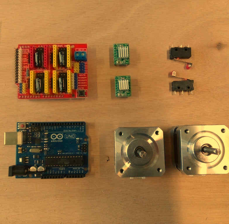
Click on name to check reference in Digikey
| Part | Quantity |
|---|---|
| NEMA 17 step motors | 2 |
| CNC GRBL arduino UNO compatible board | 1 |
| HR4988 Motor drivers | 2 |
| Limit switches | 2 |
| Arduino UNO | 1 |
| Connectors for wiring | # |
| Recycled ATX power supply | 1 |
Consumables

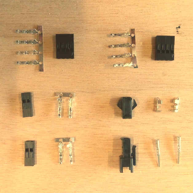
- Ribbon wire 4 colors for stepper motors
- AWG wire 1669
- Connectors “Type 1”
- Connector “Type 2”
Tools
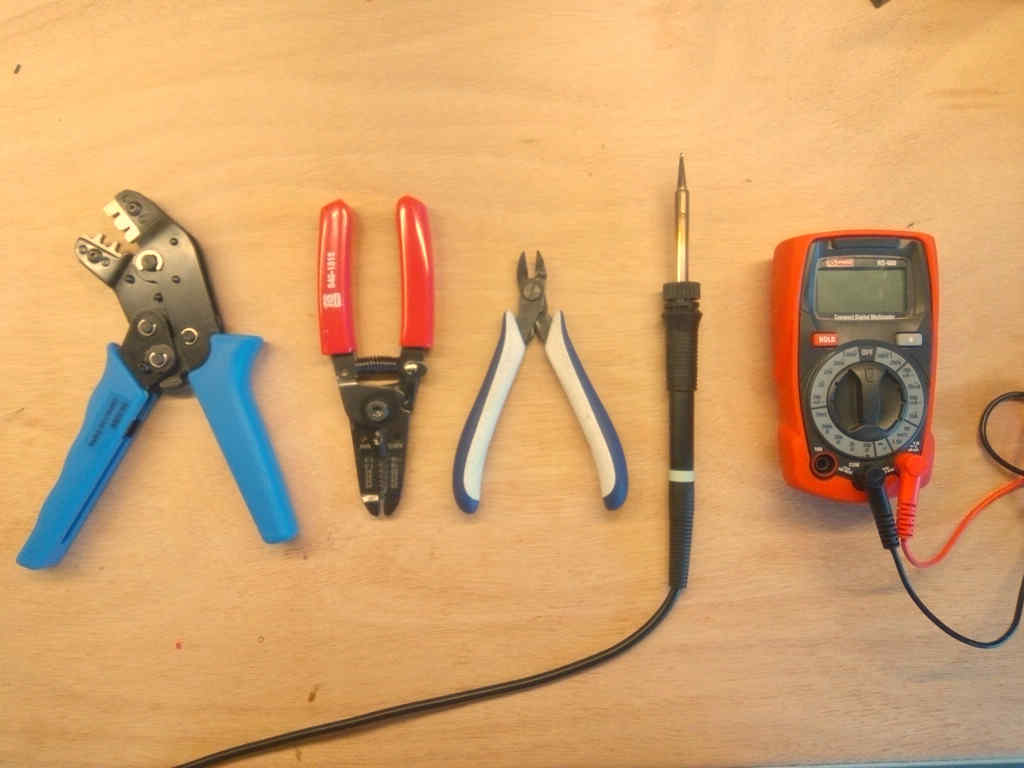
- GST Crimping Tool
- Soldering iron
- Clippers
- Multimeter
- Cross screw driver
- Wire stripper
Software
Instructions for the usage and configurations are detailed in the next steps.
Using an ATX Power supply
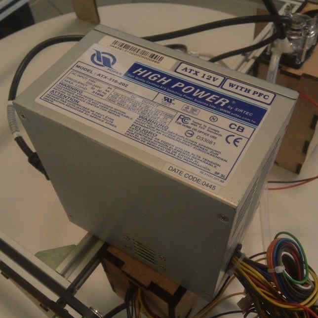
We checked possible power sources and the most suitable one was this recycled ATX power supply.
In AgriLab there’s a large stock of recycled parts and materials.
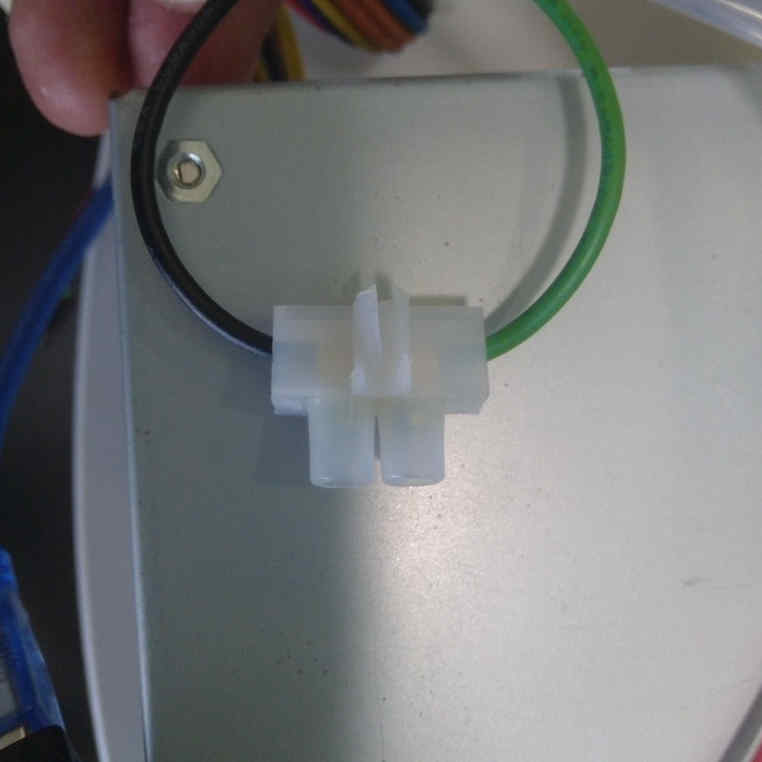
Power on jumper
To switch on the power supply I added a jumper between the green wire and ground.
Explain more
- Cut the wires
- Connect using an electrical union connector
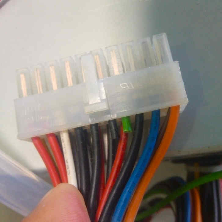
Outputs
This is the table with the Voltage and Power of every output in the ATX power supply.

I’ve used 3 pairs of 12 Volts based in the power consumption of every component listed here:
| Part | Voltage | Wire color | Black Ground wire |
|---|---|---|---|
| Arduino UNO board | 5 Volts | Red | Yes |
| GRBL board | 12 Volts | Yellow | Yes |
| 12 V Red LED | 12 Volts | Yellow | Yes |
| Peristaltic pump | 12 Volts | Yellow | Yes |
CNC control system assembly and configuration
Introduction:
The GRBL board we have it’s a common one used for CNC machines, like small low power laser cutters, small milling machines and vinyl cutters.
CNC board
This is the schematic given by the manufacturer.
Schematic has some faults in the motor driver silk
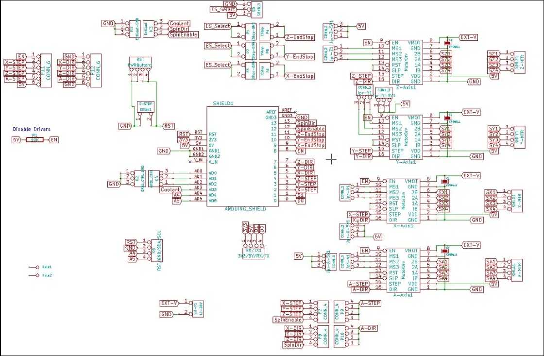
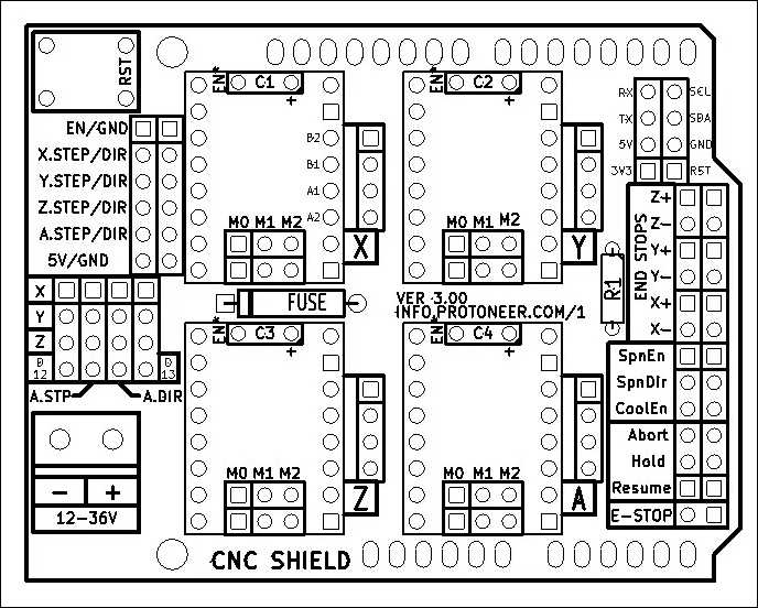
characteristics:
| GRBL | Board | |
|---|---|---|
| Operation voltage | 12 to 16 V | not regulated, only protected by a fusible |
| Axis | 3 connectors for XYZ | +1 Clone axis connector |
| Limit switches | +-X, +-Y, +- Z | |
| Spindle control | Enable, Direction, cooling | Also used for laser output control |
| Machine override controls | Abort, Hold, Resume | |
| Emergency stop | ||
| Serial communication pinouts | SDA, SCL, TX RX, RST, 3.3V 5V | |
| Microstepping configuration jumpers | 1/2, 1/4, 1/8, 1/16 |
Assembly
Connect the motor driver boards to the GRBL board sockets. Check the pinout and be sure all the pins coincide correctly.
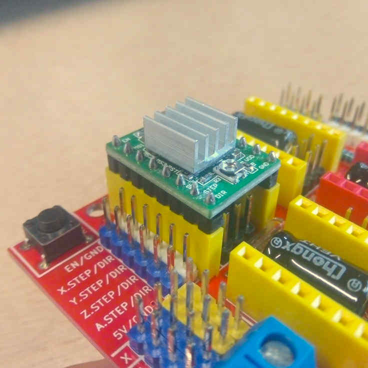
Motor drivers
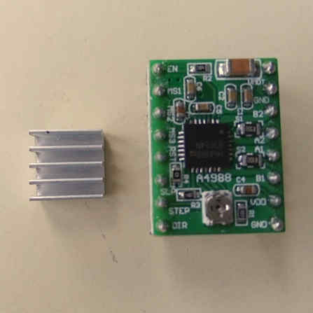
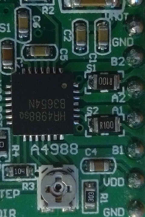
Characteristic:
| HR4988 motor driver | ||
|---|---|---|
| Operation voltage | 5 Volts | |
| Resistance | R100 | 0.1 Ohms |
| Motor Voltage Regulator | Potentiometer for VREF |
Pinouts in order:
| Left | Right |
|---|---|
| Direction | GND |
| Step | VDD |
| Sleep | 1B |
| Reset | 1A |
| MS3 | 2A |
| MS2 | 2B |
| MS1 | GND |
| Enable | VMOT |
Stepper motors
Wiring
The wiring with the stepper motors was confusing and I invested one afternoon to find out the right wiring configuration.
Following the color code the wires should be punched in the connector like this:
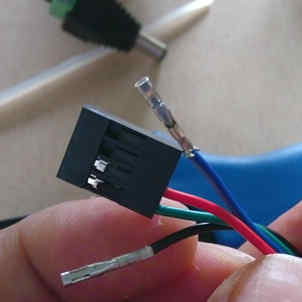
| Motor driver | Step motor |
|---|---|
| Green | Red |
| Red | Blue |
| Black | Green |
| Blue | Black |
VREF calibration
This is an important task to prevent over-heating of the motor drivers, and excessive vibration and over-heating of the step motors.
This the motor datasheet provided by the manufacturer SMD resistor calculator
Calculation:
| Values | ||
|---|---|---|
| Current Sense resistance | 0.01 Ohms | Rsense |
| Rated motor current | 1.3 A | RMC |
| Safety margin percentage | 25 % | SM |
I’ve found this formula VREF = RMC x 8 x Rsense

Process:
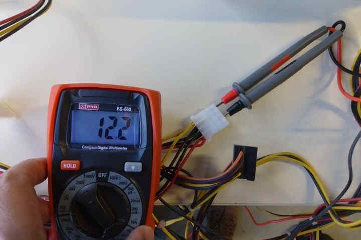
- Use the multimeter as voltmeter in a scale of less than 5 Volts.
- Get a multimeter with a clamp connector in the cathode
- Power on the GRBL board
- Place the cathode (screw driver) in the VREF potentiometer and the ground probe in the bottom left GND pin.
- Turn the potentiometer clockwise to increase and anti-clockwise to decrease the VREF.
Steps per millimeter for belt driven systems
I’ve calculated this using this calulator.
| Data | Value |
|---|---|
| Motor step angle | 1.8° |
| Driven Microstepping | Full step |
| Belt pitch | 2 mm (GT2) |
| Pulley tooth count | 20 |
Result: 5.00
| Resolution | Teeth | Step angle | Stepping | Belt |
|---|---|---|---|---|
| 200 micron | 20 | 1.8° | Full step | 2mm |
GRBL
GRBL is an Open-Source firmware that runs in Atmega328 based Arduinos for low cost CNC machines. The version I’ve used is the v1.1 released in 08/2019.
I’ve dowloaded the repository:
git clone https://github.com/grbl/grbl.git
Install requirements for Fedora Linux:
- Avr gcc compiler
- Arduino
sudo dnf install avr-gcc arduino
Once the requirements are installed, the next steps are documented in the GRBL repository.
Compiling and Flashing GRBL using Arduino IDE
- Launch the Arduino IDE
- Make sure you are using the most recent version of the Arduino IDE!
- Load the
grbl folderinto the Arduino IDE as a Library. - Click the
Sketchdrop-down menu, navigate toInclude Libraryand selectAdd .ZIP Library. TheAdd .ZIP Librarycommand supports both a .ZIP file or a folder. In our case, there is no.ZIPfile. - You can confirm that the library has been added. Click the
Sketchdrop-down menu again, navigate toInclude Library, then scroll to the bottom of the list where you should seegrbl. - IMPORTANT: Select the
grblfolder inside thegrbl-XXXfolder, which only contains the source files and an example directory. - If you accidentally select the
.zipfile or the wrong folder, you will need to navigate to your Arduino library, delete the mistake, and re-do Step 3. - Open the
GrblUploadArduino example. - Click the
Filedown-down menu, navigate toExamples->Grbl, and selectGrblUpload. - Do not alter this example in any way! Grbl does not use any Arduino code. Altering this example may cause the Arduino IDE to reference Arduino code and compiling will fail.
- Compile and upload Grbl to your Arduino.
- Connect your Arduino Uno to your computer.
- Make sure your board is set to the Arduino Uno in the
Tool->Boardmenu and the serial port is selected correctly inTool->Serial Port. (There are some controller boards on ebay that have the Arduino Pro bootloader on it, if you get error messages like “avrdude: stk500_getsync() attempt n of 10: not in sync: resp=0x20” then choose another board, try Arudino Pro/Pro Mini) - Click the
Upload, and Grbl should compile and flash to your Arduino! (Flashing with a programmer also works by using theUpload Using Programmermenu command.)
Compiling and flashing using command line tools
Requirements for Fedora Linux
GRBL repository:
git clone https://github.com/grbl/grbl.git
AVR-GCC and Arduino core libraries:
sudo dnf install avr-gcc arduino-core
Make:
sudo dnf install make
Usage
Go to your local GRBL repository using your terminal by cd
cd $HOME/repos/grbl
Then use make to compile the grbl HEX file that’s going to be flashed to your Arduino UNO board:
make clean && make grbl.hex
If the HEX file is successfully compiled then proceed to flash it to the board by executing:
avrdude -v -patmega328p -Uflash:w:grbl_v1.1h.20190825.hex:i -carduino -b 115200 -P /dev/ttyACM0
Where:
-
/dev/ttyACM0 it’s the local addres of my Arduino UNO board.
-
-patmega328p it’s microprocessor family
-
-Uflash:w:grbl*.hex it’s the grbl_file_name.hex you have compiled.
-
b 115200 it’s the baudrate speed.
There are different ways to know this value, the easiest one it’s this:
- Execute on the terminal with your board unplugged:
ls /dev/tty*
Save the output and then execute the same command again, but with your Arduino board connected, compare the difference, and the new address it’s the one of your Arduino:
Disable Z axis homing routine
After flashing the board, and setting up electronics and power source I tried to configure the homming using Universal Gcode Sender but, I got many alarms in the process of trying the limit switches. Remember I’m using a 2 axis configuration in hardware but then the GRBL by default expects Z axis limit switch in the routine.
We need to edit and re-flash the firmware to the board, this are the steps needed:
In the lines 75 and 76 of the grbl/config.h file its declared the homing process and as the comments point:
-
line 75 moves the Z axis which is not existing in our configuration,
-
line 76 moves the XY axis at the same time and rate.
This whole process it’s called “limit finding”:
Edition:
-
Comment line 75 by adding double slash “//” at the begging of the line.
-
Edit line 76 by changing “HOMING_CYCLE_1” to “HOMING_CYCLE_0”.
-
Save the file, and run the compilation process with Arduino or Linux command tools.
Now the homing cycle starts by moving the X and Y axis and the errors are fixed.
Firmware configuration
The important points of the firmware configuration are:
-
Report in inches, which means you need to disable it to use millimeters.
-
Homing cycle enabled, this is required since we’re using a band-pulley system, and as result the machine is not precise enough to preserve an reliable 0 position.
-
Working area limits:
- X: 310 mm
- Y: 290 mm
We obtained this measurements by manually measuring the travel length of each axis.

Firmware configuration table:
| Setting | Value | Description |
|---|---|---|
| $0 | 10 | Step pulse time |
| $1 | 25 | Step idle delay |
| $2 | 0 | Step pulse invert |
| $3 | 2 | Step direction invert |
| $4 | 0 | Invert Step enable pin |
| $5 | 0 | Invert limit pins |
| $6 | 0 | Invert probe pin |
| $10 | 1 | Status report options |
| $11 | 0.010 | Junction deviation |
| $12 | 0.020 | Arc tolerance |
| $13 | 0 | Report in inches |
| $20 | 1 | Soft limits enable |
| $21 | 0 | Hard limits enable |
| $22 | 1 | Homing cycle enable |
| $23 | 7 | Homing direction invert |
| $24 | 25.000 | Homing locate feed rate |
| $25 | 700.000 | Homing search feed rate |
| $26 | 250 | Homing switch de-bouncing delay |
| $27 | 1.000 | Homing switch pull-off distance |
| $30 | 10000 | Maximum spindle speed |
| $31 | 0 | Minimum spindle speed |
| $32 | 1 | Laser mode enabled |
| $100 | 5.000 | X-axis travel resolution |
| $101 | 5.000 | Y-axis travel resolution |
| $102 | 5.000 | Z-axis travel resolution |
| $110 | 10000.000 | X-axis maximum rate |
| $111 | 10000.000 | Y-axis maximum rate |
| $112 | 500.000 | Z-axis maximum rate |
| $120 | 5000.000 | X-axis acceleration |
| $121 | 5000.000 | Y-axis acceleration |
| $122 | 10.000 | Z-axis acceleration |
| $130 | 310.000 | X-axis maximum travel |
| $131 | 290.000 | Y-axis maximum travel |
| $132 | 0.000 | Z-axis maximum travel |
Valid GCODE
I’ve the time to test multiple GCODES compatible for this version of GRBL.
| Code | Action |
|---|---|
| $H | Starts homing cycle |
| $G28 | Goes to the maximum point |
| $G0 X100 | Linear movement on X axis by 100 mm |
| $G0 Y100 | Linear movement on Y axis by 100 mm |
| $G0 X100 Y100 | Linear movement on X and Y axis by 100 mm |
| $G53 | Uses absolute coordinates for positioning |
| $G27 | Uses XY plane |
Wiring and connections
- Connect motor driver boards to the CNC arduino shield
- Connect stepper motors with the correct wiring configuration specified in the stepper motors section.
- Connect X and Y limit switches to -X and -Y ports in the board.
- Connect power supply yellow and black cables from the ATX power supply.
- I’ve included a 12 V Red led to give some visual feedback, it’s connected by an independent yellow and black wires from the ATX power supply.
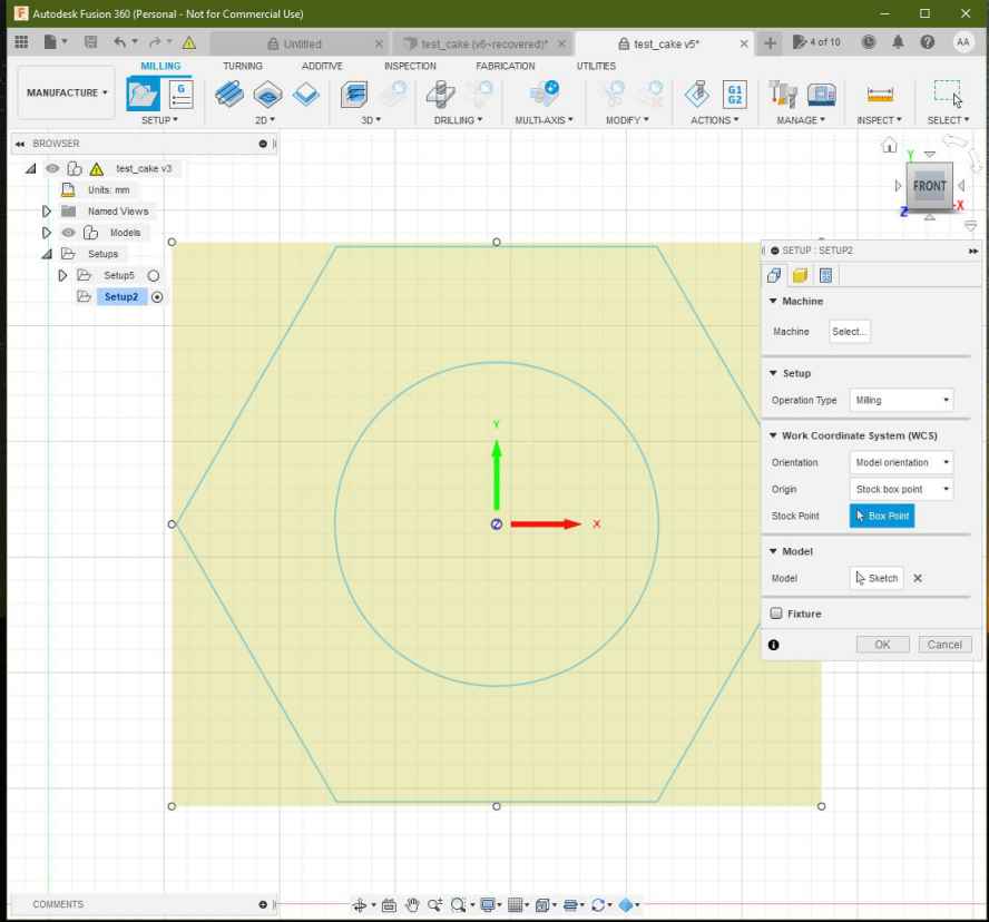
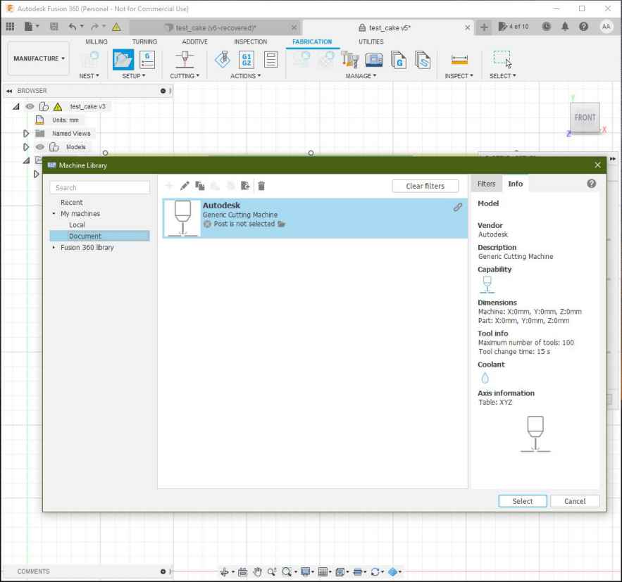
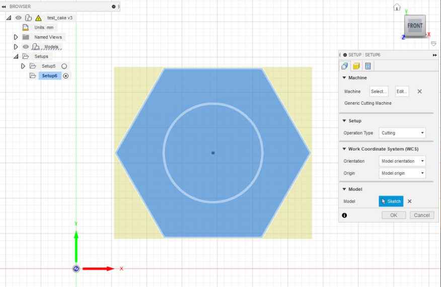
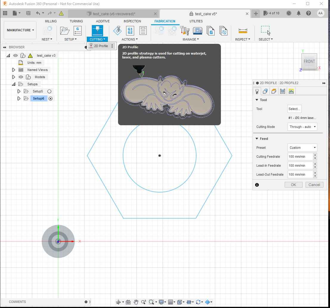
Fusion 360 work-flow
I’ve used Autodesk’s Fusion 360 to understand how the process of making GCODE works with a familiar software. Although there are other options like LaserWeb
Design
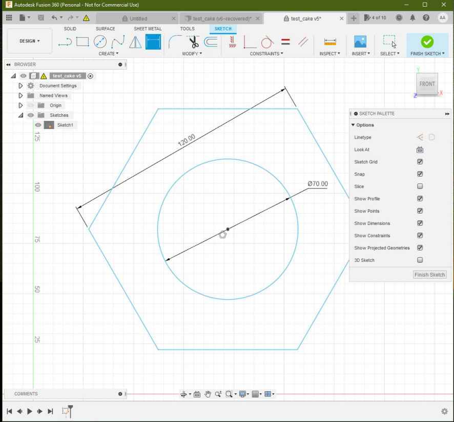
The Design process conssit just in drawing a shape using the sketch tools under the Design environment of Fusion 360.
I’ve simple shapes to test the
Manufacturing

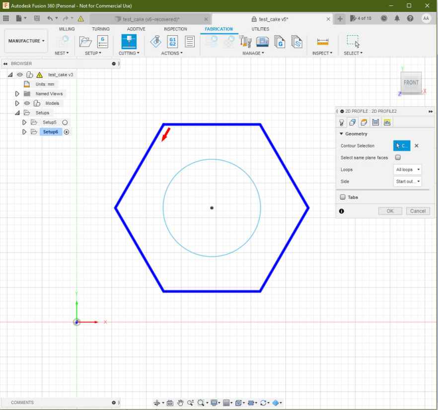

Simulation
NC file post-processing

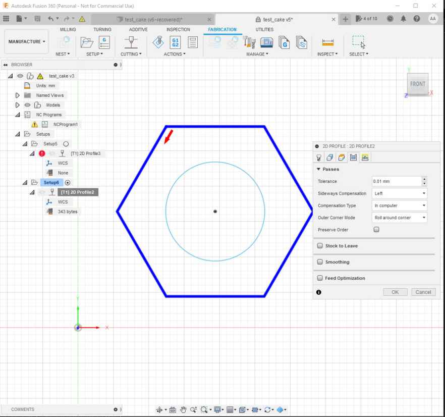

%
(cake_test_01)
(Machine)
(  vendor: Autodesk)
(  description: Generic Cutting Machine)
G90 G94
G17
G21

(2D Profile2)
G54
G0 S255 M4
G0 X62.576 Y25.508
G1 X61.576 Y23.776 F1000
G1 X62.447 Y22.268
G1 X131.498
G1 X166.023 Y82.068
G1 X131.498 Y141.868
G1 X62.447
G1 X27.921 Y82.068
G1 X61.576 Y23.776
G1 X63.576
G1 S0
M30
%
Universal GCODE sender
-
Download Universal GCODE sender
-
Run Universal GCODE sender and activate the communication with the machine
- Establish serial communication at 115200 bauds
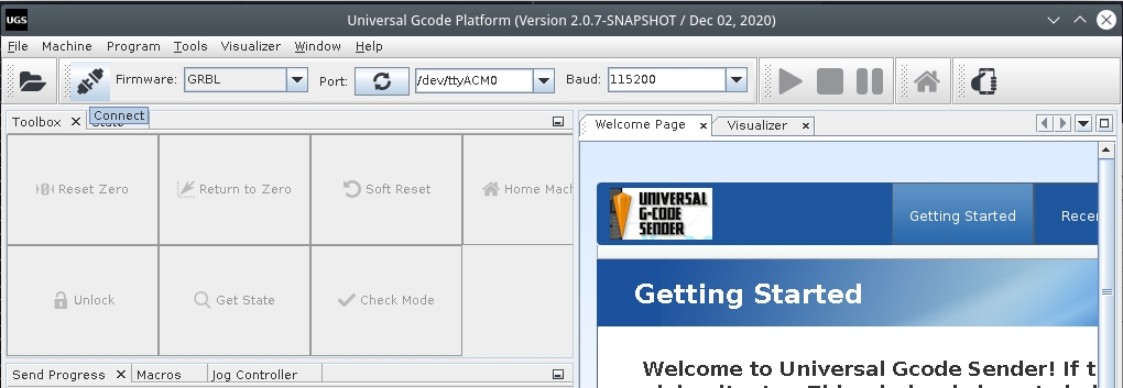
- Run the HOME cycle
- Import the GCODE in “File” –> “Open”
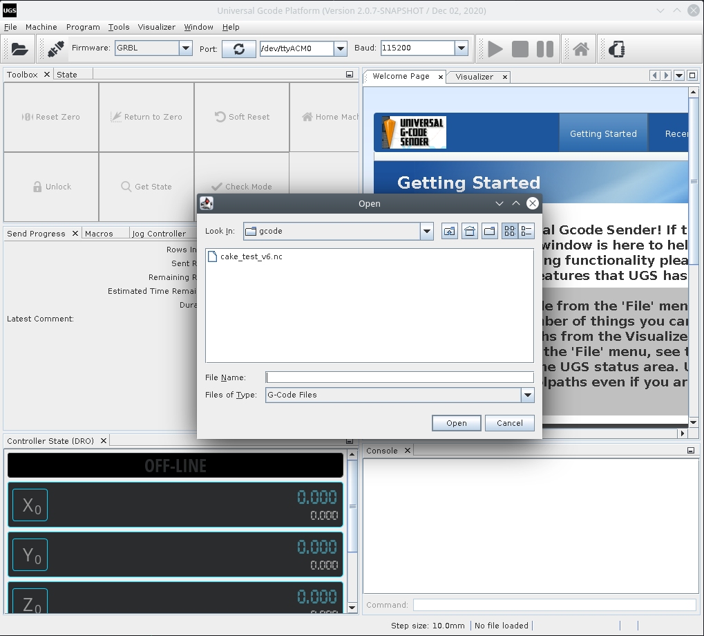
- Press the “Play” Button to run the GCODE
Troubleshooting
- Slow speeds:
Change the maximum acceleration on the firmware configuration:
- High vibration:
Decrease the motor drivers VREF until the vibration gets reduced
- Axis not moving:
Check the transmission band, look for any stuck parts or excessive friction. Adjust the motor drivers VREF increasing the output
- Motors not changing direction
I’ve found that the silk labels on the motor drivers are inverted and thus it gets confusing if you try to connect the stepper motors following the schematics.
Conclusion and future
For the future we will be able to make some modifications such as :
- Adding a rasberry pie for ease of use.
- More solid feet
- A guide for the belt, it rubs along the profile which can damage it quickly
- A hot plate specially designed for our machine