6. 3D Scanning and printing
Security assessment:
Plastic particles in air:
As in the printing process we are heating plastics and then use a fan to cooldown the layers it’s very important to know that we’re actually emitting dangerous plastic particles to the air.


So to prevent any hazardous environment follow this basic checklist:
- Avoid the use of dangerous materials like ABS, instead try to use PLA if the mechanical properties are not important for your piece.
- Use a HEPA air filter system in the room and keep it turn on while printing in the room. Keep a good maintenance of the filter, replacing or washing periodically the filter cartridges.
- Once your printing is running and everything seems working fine, stay away from the room.
- After every work ventilate the room by opening the windows.
- If possible work with a closed cased 3D printer.
- If you need to stay close in the same room of the printer for large amounts of time, use a face mask or particle gas mask.
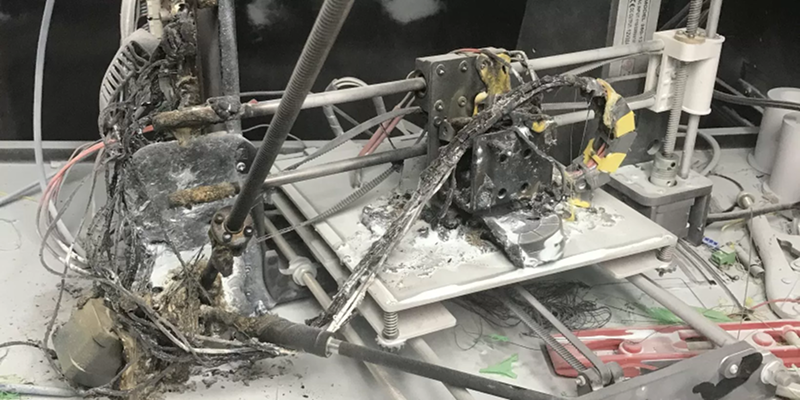
Fire risk:
As the FDM printing process requires high temperatures to melt the plastic, there’s some risk associated to the usage of the machine.
Checklist to prevent fires while 3D printing:
- Check that the heat sensors work correctly.
- Look for any sign of wearing of the insulation that covers the nozzle.
- Look for any melted parts of the 3D printer that can indicate a over-high temperature.
- Take a look at the board components and try to identify any over heating on the motor drivers.
- Use safe temperature materials, there are some exotic mixes that require higher temperatures.
- Check that all the cooling fans are working correctly.
- Check if you have the right setttings for the material.
- Try to split large models into ~8 to 10 hours parts.
- Avoid prints that are very long.
- Install Octoprint or astroprint to monitor online your prints.
- Place the 3D printer in a safe environment far away from any fast combustion materials or any other temperature sensitive chemicals.
- Have a fire extinguisher at hand.
Cross contamination:
There are some people interested on food-safe or biomedical 3D printing parts. But there’s some risk associated to the FDM process that makes very difficult to make safe printed parts.
Food-safe manufacturing checklist:
- Change the brass extruder nozzle for one made of lead-free staninless steel.
- Use a closed cased 3D printer.
- Use a lead-free glass for the printer bed.
- Use a lead-free material.
- Print with the higher resolution to reduce the ammount of porosity on the part surface.
- For posprocessing you can cover the part with Teflon, Transparent resin or try electroplating.
Food-safe use of 3D printed parts:
- Clean inmediately after every usage, to avoid the food impregnate on the part surface.
- Don’t put any reactive substance in the 3D printed part.
- If you’re using a dishwashing machine, check the temperatures to avoid any deformation on the part.
- Be conscious that there’s no possibility to have a long-lasting 3D print part, so you need to dispose the part after it shows signs of wearing in the food-safe coating.
Creality ender 5 plus
Test designs
Clearance
Test of the printer Creality ender 5 plus.

There is two kind of system, the extruder system with a tube, named Bowden and the direct drive system, without tube.
Here is the Bowden system

Here is the direct drive system

The Creality ender 5 plus is working with a Bowden system.
The set of the height of the bed depends on the device. The creality cr10 is fully manual of the z, we take a paper to see. For the creality 5+ it is a physical sensor.

To change the filament on the creality, we need to warm the nozzle. When it is warm, we remove the filament, then we trap the new filament and put it in the sensor, we push it straight with the hand, wait it to get out then click on “feed” on the device to bring it well.


First I wanted to do some test to check the gap between 2 shapes that can handle the device to be able to do some jointures. I downloaded a file to test the clearance of the device, available on the fabacademy website. I made all the tests for the Creality 5 plus.
After downloading the .stl file for clearance I clicked and dragged it on the Cura software.
First I chose my printer. I picked the Creality 5 plus to make the tests. I set some parameters like adding a brim under the shape, infill the density at 20%, because it wanted to print my test in a few time. I generate a support for the shape because if the printer print in the air I wont get the shape I want.

I checked the temperatures of the plate and the printing on the filament spool.

I sliced my shape to see how many time will the printing take and how will my shape will be print.

I also checked with the right cursor the layers of the printing.

And I finally download the .gcode file and put it on the micro SD card readable by the device. Then I started the printing and checked if everything started well.
Here is the main settings of the printing :
- layer height: 0.2 mm
- infill density: 20%
- infill patern: cubic
- printing temeprature: 200°C
- build plate temperature: 60°
- build plate adhesion type: brim
The result is pretty good at the end, I just have to remove the support.

First I tried with ultrasonic cutter but it melt my shape.
So I used a normal cutter, I removed the support, but maybe because of the infill I set at only 60%, the shape broke in two parts when I made a lever with the cutter.

We still can se the result and now I know how to set the clearance I need to design my shapes.

So for the clearance, the setting has to be over 0.2 mm to be able to remove a shape from another shape. The hole must be wider than 0.2 mm. Maybe if I have printed the shape on another side, vertical instead of horizontal, the result could have been different.
Overhang
I also made the test of overhang to see how the printer is dealing with printing overhang without support. Here is .stl file for overhang. This files comes from the fabacademy website

At the end, with a 10 mm overhang, the printer can still do it but it is becoming really messy under.

We can see that at the end it becomes worst. The top of the shape is still appearing clean, but when the flat is longer, the under is worst, that’s why I have to design my shape not flat, but with some angle.
Full board test
I looked for a test board that print many test, to check until where I can set angled shapes without support, the bridges, the precision of the printer in doing cylinders, and holes in circles and rectangles. You can find the file on thingiverse.com
Here is the final result that should appear.

First the Creality ender 5+ didn’t print the writing on the the shape. We can read the writings that are make with holes.

To test the precision of the priting I compared the size of what the result would be and what were really print.

For the cylinders, there is a difference of 0.1 mm at the external diameter.
| Expected | Real |
|---|---|
| 10 mm | 9.9 mm |
| 8 mm | 7.9 mm |
| 6 mm | 5.9 mm |
| 4 mm | 3.9 mm |
For the hole test, circles the printers is not really precise
| Expected | Real |
|---|---|
| 8 mm | 7.6 mm |
| 6 mm | 5.2 mm |
For the hole test, rectangles the measures are really good
| Expected | Real |
|---|---|
| 4 mm | 4 mm |
| 3 mm | 3 mm |
| 2 mm | 2 mm |
All the measure depends also of the measurement accuracy.
For the angles, from 50 degrees, we start to see really the lines of plastic printed.


We can see that the bridges pitch over 15 mm.
For the overhang test, after 50° we really start to see the lines of plastic printed.
Description of Ultimaker 3 Extended

The Ultimaker 3 Extended 3D printer is the large format version of the Ultimaker 3. This allows you to print larger objects. With high printing accuracy and ease of use, it allows complex objects to be printed without too much difficulty. With its PrintCore system, the print heads are interchangeable and adapted to each material. This results in a more homogenous and precise deposit and reduces the risk of nozzle clogging. The double extrusion system allows you to combine printing materials with soluble substrates to create more complex parts. You can also make colour prints.
| Device | |
|---|---|
| Designation | Ultimaker 3 extended |
| Computer interface | USB, Wifi, Ethernet |
| Print head | 2 heads |
| Printing speed | 300 mm/s |
| Print volume | 215 x 215 x 200 mm |
| Consumable materials | ABS, PLA, Nylon, CPE, Polycarbonate, PVA |
| Number of colours | 2 |
| Nozzle diameter | 0,4 mm |
| Max. nozzle temperature | 280°C |
| Max plate temperature | 100°C |
| Filament diameter | 1,75 mm |
| Layer thickness | 20 micron |
| OS accepted | Windows, Mac OS X and Linus |
| Physical characteristic | 688 x 493 x 338 mm |
| Weight | 11,3 kg |
The torture test :
To characterize the machines we decided to use the Cura software to slice our object. This software is open-source and is available for all our OS (yes we are 3 and we have a Windows, a Linux and a Mac). Moreover we agreed on the object to be printed. We found this file on the Internet which we then shared with each other. We also chose to have the same print settings to achieve a good benchmark.

Print settings :
- Material : PLA
- Layer height: 0.2 mm
- Wall Thickness: 0.8 mm
- Nozzle: AA 0.4 mm
- Infill: 20% tri-hexagon
- Printing temp: 205°C
- Bed temp: 60°C
- Print Speed: 70 mm/s
- No support
- Adhesion Platform : Brim
Printing time: 5h 28 min

Results for the Ultimaker 3 extended

| Test | Comments |
|---|---|
| External diameters | 9.8 mm instead of 10 mm, 7.8 mm instead of 8 mm, 5.8 mm instead of 6 mm, 3.8 mm instead of 4 mm |
| Inner hole | 7.5 mm instead of 8 mm, 5.5 mm instead of 6 mm |
| Angles | No more than 45° |
| Bridge | Pitch over 15 mm |
| Corners | All corners are rounded |
| Writing | The writing on the top is not legible because the layers are too high. If we had set the layers to 0.1 mm the writing would have been more visible. |
We can see that the Ultimaker 3 Extended is a machine that is quite accurate. We can see an accuracy of 0.2 mm on average for outside diameters. For the inside diameters we can see an inaccuracy of 0.5 mm but this may be due to a measurement error, I couldn’t get the calliper in the hole which was too small. Concerning the angles, we can see that if the angle is greater than 45° then the layers are no longer accurate. A length of more than 15 mm also leads to an inaccuracy of the lower layers which are in the void.
Note: you can see that all right angles are rounded. This is due to the fact that the nozzle sends a round jet. It is therefore impossible to create a right angle with a protruding edge. Of course this is really very small and is equivalent to the diameter of the nozzle, so the right angle is slightly rounded by a few millimetres.
Benchmark test for Creality CR10 S5

Tech specs:
-
General Specifications
- Technology: Fused deposition modeling (FDM)
- Year: 2019
- Assembly: Partially assembled
- Mechanical arrangement: Cartesian XY-head
- Manufacturer: Creality
-
3D Printer Properties
- Build volume: 500 x 500 x 500 mm
- Feeder system: Bowden
- Print head: Single nozzle
- Nozzle size: 0.4 mm
- Max. hot end temperature: 260 ℃
- Max. heated bed temperature: 60 ℃
- Print bed material: Glass
- Frame: Aluminum
- Bed leveling: Manual
- Connectivity: SD card, USB
- Print recovery: Yes
- Filament sensor: Yes
- Camera: No
-
Materials
- Filament diameter: 1.75 mm
- Third-party filament: Yes
- Filament materials: Consumer materials (PLA, ABS, PETG, Flexibles)
-
Software
- Recommended slicer: Cura, Simplify3D, Repetier-Host
- Operating system: Windows, Mac OSX, Linux
- File types: STL, OBJ, AMF
-
Dimensions and Weight
- Frame dimensions: 690 x 800 x 715 mm
- Weight: 14.6 kg
Small cubes test:

Cube 1 (Success):
Parameters:
| Parameter | Value |
|---|---|
| Material | PLA |
| Layer height | 0.25 mm |
| Speed | 20 mm/s |
| Extruder Temp | 200 C |
| Plate Temp | 50 C |
| Infill | 10 % |
| Wall count | 3 |
| Skirt | True |
Cube 2 (Fail):
Parameters:
| Parameter | Value |
|---|---|
| Material | PLA |
| Layer height | 0.30 mm |
| Speed | 20 mm/s |
| Extruder Temp | 200 C |
| Plate Temp | 35 C |
| Infill | 10 % |
| Wall count | 3 |
| Skirt | True |
Cube 3 (Success):
Parameters:
| Parameter | Value |
|---|---|
| Material | PLA |
| Layer height | 0.30 mm |
| Speed | 20 mm/s |
| Extruder Temp | 200 C |
| Plate Temp | 60 C |
| Infill | 10 % |
| Wall count | 3 |
| Skirt | True |
Benchmark test model:
First try(Failed):

Parameters:
| Parameter | Value |
|---|---|
| Material | PLA |
| Layer height | 0.25 mm |
| Speed | 20 mm/s |
| Extruder Temp | 200 C |
| Plate Temp | 55 C |
| Infill | 10 % |
| Wall count | 2 |
| Skirt | True |
Second try(Failed): Parameters:
| Parameter | Value |
|---|---|
| Material | PLA |
| Layer height | 0.25 mm |
| Speed | 30 mm/s |
| Extruder Temp | 200 C |
| Plate Temp | 50 C |
| Infill | 10 % |
| Wall count | 2 |
| Skirt | True |
Third try(Success):

Parameters:
| Parameter | Value |
|---|---|
| Material | PLA |
| Layer height | 0.25 mm |
| Speed | 40 mm/s |
| Extruder Temp | 200 C |
| Plate Temp | 65 C |
| Infill | 10 % |
| Wall count | 2 |
| Brim | True |
Notes: After calibrating the Z axix the print sticked to the build plate correctly and I was able to print overnight. From Friday evening and as we don’t have access to the lab during the weekend I checked from outside that the print was correctly.
Z axis Calibration:
Checklist:
- Turn on the printer.
- Make the cart go to the home position.
- Disable steppers.
- Move the cart to the closest corner of the build plate.
- Using a small piece of normal bond paper, check the Z axis distance to the plate by passing through the nozzle and the build platform.
- If you feel the paper passing too tight, lose the Z axis bolt, until the paper passes thoroughly.
- Move to the next corner and repeat the steps 3 to 5.
- Once all the corners are adjusted move to the center.
- Enable steppers again and make a test print.
- If the print sticks to the printing bed the calibration was successful.
- If not, repeat the process, until it’s successful.
Troubleshooting:

Print not sticking to build plate:
When the machine Z axis is far from the build plate it’s very likely that the printing is not going to stick to the bed. If that happens you need to check the Z axis calibration, follow the checklist.
Warp:
When the build plate is too cold, the plastic shrinks quickly and the difference of contraction between the first layers and the current ones it makes the piece to warp and detach to the build plate.
Elephant feet:
When the Z axis is too close to the bed, the fused filament can make a bigger base that looks that a elephant feet.
Melted points:
When the temperature it’s too high and the speed it’s too slow, the filament will look very low detailed and melted looking.